IEEE TRANSACTIONS ON DEVICE AND MATERIALS RELIABILITY, VOL. 14, NO. 3, SEPTEMBER 2014
857
Mechanical Reliability of Embedded Array Capacitors in Ultrahigh-Performance Microprocessors Rahul Panat, Sriram Dattaguru, Haluk Balkan, Yongki Min, Huankiat Seh, and Xinyan Zhao
Abstract—Increasing power delivery and performance requirements for next-generation Intel microprocessors has led to the need for a high-capacitance low-inductance decoupling option very close to the die. An embedded array capacitor (EAC) is a large array capacitor embedded in the high-density interconnect (HDI) substrate core and provides a low-inductance path to the die. This paper describes technology development challenges encountered while enabling EACs on Intel’s advanced microprocessors. Various package interfaces resulting from the EAC embedding showed very high stress and propensity to delaminate. These defects were addressed by tailoring suitable materials and process modifications during the manufacturing process. Expansion of the embedding material in the HDI substrate resulted in high C4 area warpage. This led to issues such as solder bump bridging, underfill voids, and reliability fails. The technology development challenges and the solution paths described in this paper are very useful to industry in understanding the integration of advanced decoupling options in ultrahigh-performance microprocessor packages. Index Terms—Embedded array capacitors, energy storage in microprocessors, ultrahigh performance microprocessors, servers, package reliability, passives.
I. I NTRODUCTION
C
APACITORS are used to manage the impedance of the power delivery path of a microprocessor package. The package impedance peaks at certain (operating) frequencies, with the peaks described as impedance droops [1]. In some applications, the droop requirements can necessitate the use of a high capacitance source with very low inductive losses. Placing an embedded capacitor inside the substrate core in very near proximity of the microprocessor is one such option [1]–[4]. The EAC is a rectangular ceramic block with the principle of operation the same as conventional multi-layer-ceramic-capacitors (MLCC), i.e., metal electrodes separated by a ceramic dielectric Manuscript received October 31, 2013; revised May 17, 2014; accepted June 10, 2014. Date of publication June 13, 2014; date of current version September 2, 2014. R. Panat was with the Assembly and Test Technology Development, Intel Corporation, Chandler, AZ 85226 USA. He is now with the School of Mechanical and Materials Engineering, Washington State University, Pullman, WA 99164 USA (e-mail:
[email protected]). S. Dattaguru, H. Balkan, and Y. Min are with the Assembly and Test Technology Development, Intel Corporation, Chandler, AZ 85226 USA. H. Seh was with the Assembly and Test Technology Development, Intel Corporation, Chandler, AZ 85226 USA. He is now with CoAssets Inc., Singapore 059294. X. Zhao is with the Failure Analysis Group, Intel Corporation, Chandler, AZ 85226 USA. Color versions of one or more of the figures in this paper are available online at http://ieeexplore.ieee.org. Digital Object Identifier 10.1109/TDMR.2014.2331023
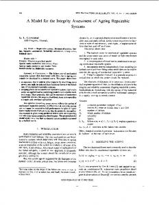
Fig. 1. Schematic of EAC inside an Intel package.
[2]. The EAC is typically significantly larger in size (area as well as thickness) compared to the discrete MLCC capacitors. Fig. 1 shows a schematic of an EAC inside a microprocessor package. The EAC is placed inside a cut-out within the HDI substrate core and the surrounding space is filled with a plugging material which is cured before the substrate build-up (BU). Alternate EAC electrodes are connected to power and ground so that the capacitance is in parallel to the power supply. Typical EAC length and width is of the order of several mm, while the thickness is of the order of substrate core, i.e., in the range of a mm for ultrahigh performance packages. Fig. 2 shows the power delivery network impedance for the embedded array capacitor prototype when compared to the traditional design from [1]. Clearly, the EAC has reduced the droop at the highest frequencies needed for high performance microprocessors. From Fig. 1, the complexity of the package structure with an embedded EAC is quite obvious. First, the cut-out in the HDI substrate provides an easy path for core moisture to escape, giving rise to a chimney like region that can be susceptible to “popcorning” if the BU copper is not designed properly [5]. Secondly, introduction of a large ceramic body into the substrate core gives rise to several dissimilar materials in close proximity to each other. Dissimilar CTE values of the
1530-4388 © 2014 IEEE. Personal use is permitted, but republication/redistribution requires IEEE permission. See http://www.ieee.org/publications_standards/publications/rights/index.html for more information.
858
IEEE TRANSACTIONS ON DEVICE AND MATERIALS RELIABILITY, VOL. 14, NO. 3, SEPTEMBER 2014
Fig. 3.
A typical EAC tile.
Fig. 4.
EAC tiles with rounded and chamfered edge design.
Fig. 2. The measured power delivery network impedance for the embedded array capacitor prototype when compared to the traditional design [1].
ceramic (2 ∼ 3 ppm/C), the cavity filling polymer composite or Materials A (> 15 ppm/C), the BU polymer composite or Material B (> 15 ppm/C), and the build-up copper (∼17 ppm/C) can give rise to high internal stresses. Third, many new interfaces are introduced in the system. The Material A forms interfaces with the Material B on two sides, EAC ceramic on the third side, and core on the fourth side. Both material A and material B are epoxy based polymers with proprietary additives with different silica filler % to provide the required stiffness. The typical filler % in Material A is about 1.3× to 1.5× that of Material B. The EAC is expected to expand negligibly in the thickness (Z) direction when compared to the EAC cavity material and the core at reflow temperature. This difference will be directly reflected into the warpage of the C4 area—impacting the first level interconnect (FLI) joint formation process. Lastly, the risk of ceramic cracks during the high pressure of the substrate BU process cannot be discounted. Note that Material A is the “new” material in the package since the substrate core and the build-up polymer/Cu come from standard substrates (legacy materials). With all these complexities described above, the entire structure goes through multiple reflows above 200C, viz. Pb-free bumping, external capacitor mount, and chip attach [6]. Other technologies in embedding are the Thin Film Capacitor (TFC) [7] or embedding MLCCs in the substrate core. These options, however, provide limited capacitance not suitable for high performance microprocessors. For example, the capacitance of discrete MLCCs is similar to EAC for a given configuration (i.e., number of active layers, the area, and the layer thickness). The EAC can provide high total capacitance close to the core due to its larger active volume. The EAC technology development process involved starting from the concept EAC test vehicle (TV) with low PCB layer count to a highly complex TV with high PCB layer count. Initially, the EAC TV showed high rates of interfacial delamination at Material A-Material B interface. These defects were fixed by improving interfacial bonding during substrate manufacturing. Even when the interfacial delamination was fixed, the dissimilar material expansion in thickness direction resulted in higher chip warpage at room temperature and at high temperature. The PCB warpage resulted in issues such
as solder bump bridging and epoxy voids. In addition, package failures showed up during reliability under temperature cycling. Through changes to the embedding material, solder bump bridging was reduced and the underfill voids and reliability failures eliminated. The EAC technology evolved from a simple concept [2] to realization in a microprocessor package providing the required microprocessor performance advantage. II. EAC C ONSIDERATIONS In this section we describe the considerations while choosing the EAC solution. An EAC being a rectangular capacitor tile (see Fig. 3) similar to MLCCs, is constructed from high-k dielectric ceramic layers that are printed with patterned metal layer on each dielectric surface [2], [3]. These layers are processed together to form a rectangular tile, with top and bottom surfaces covered with copper that are patterned into planes and pads [9]. The surface of EACs consisted of copper metal pads that were electrically isolated from the plane surround them. The metal pads were linked to the power rail, while the rest of the metal plane was linked to ground through vias connecting with the EAC. Internally, the EAC comprised of alternate layers of ceramic and metal running horizontally with vertical vias. In general, smaller the EAC tile, smaller is the capacitance for an equal via density. Note that the edge shapes of the EAC tile can also be changed to address stress concentration issues. Schematic of EAC tiles with chamfered or rounded edges are shown in Fig. 4. Note that a single EAC tile can be internally split into multiple partitions that can be isolated electrically from each other [8]. These partitions are helpful in providing separate capacitances to individual microprocessor cores through
PANAT et al.: MECHANICAL RELIABILITY OF EACs IN MICROPROCESSORS
859
Fig. 5. Cross-section of an EAC without partition versus one with multiple partitions [8].
Fig. 7. Crack near to trace ending above cavity after temperature cycles (Material A).
Increasing the total number of dielectric layers could help increase EAC capacitance density—however, this approach was limited by the reduced positional accuracy of the drill for large number of dielectric layers. Lastly, designers would like to reduce the non-active volume of the EAC to increase the capacitance; however, the non active regions of the EAC are needed to protect the EAC internal parts from the chemical solutions of the HDI substrate processes. The optimum package vs EAC size/thickness is determined by electrical requirements, i.e., the need for a source of capacitance near a microprocessor core. Of course, the maximum EAC thickness is limited by the core thickness of the substrate in the current configuration. Fig. 6.
Shows the interplay between different EAC features.
multiple power rails. Theoretically, the tile could be made with several more partitions but since the area between the partitions is non-active, the capacitance of the tile reduces. The schematic in Fig. 5 compares the cross section of EAC tile with single capacitor to that of one with multiple partitions within the EAC [8]. The dimensions of each of the features on EAC were designed based on functional, manufacturing or reliability considerations. We will describe these aspects in this section. Several key considerations exist in the design of the surface pad and plane dimensions, namely, the via dimension, the alignment accuracy in combination with the needed adjustment for pad-to-via alignment due to panel shrinkage during the HDI substrate manufacturing. In the present case, the diameter of via landing on EAC was a topic of focused investigation during initial research. Via diameter determined not only the EAC pad, but also the top layer pad covering it. The via size diameter was optimized to ensure that the via integrity was preserved under high stress due to ceramic/polymer CTE differences while allowing sufficient vias to land on the EAC based on the required partitions. As the vias were drilled to meet the EAC metal pad, the top layer pad had to be patterned to cover the via in the next buildup pattern process. As we used a larger via, a larger pad had to be designed that accommodated not only the required via size, but also the pad-to-via alignment accuracy, any underlying padto-pad deviations, and any differences/uneven shrinkage at this ceramic area versus rest of the polymer core. Fig. 6 summarizes the design considerations described above.
III. E XPERIMENT The substrates were manufactured with modified PCB process to embed EAC in the core. The substrate was then attached with the die to form an FLI joint. Finally, a polymer underfill was used to reinforce the die-substrate gap as is done in a standard microprocessor packaging process [6]. The packages were then subjected to reliability stressing per JEDEC temperature cycle standards (Temp cycle—B) to ensure reliability performance. The cavity between EAC edge to the opening in the substrate was filled with a polymer composite which was selected to ensure interfacial integrity (Material A of Fig. 1). Risks to package reliability can be seen in Fig. 7. Upon curing, severe stress points at the EAC edge caused the structure to crack; an example is shown in Fig. 7. Several design iterations were needed to reduce the stresses and resolve this issue. The selection of the polymer material in filling the EAC cavity was of utmost important as the material was needed to bond well to three dissimilar materials (1. HDI substrate core; 2. EAC tile; 3. build up material) at room temperature. In addition, it was expected to keep the stress at minimum during the entire thermal cycling during the various process. The surface roughness of the polymer filling material was also an important factor for good adhesion to the subsequent build up material. In the next section two major quality issues will be outlined which were solved by selecting optimum polymer material (Material A of Section II) and an optimum surface treatment before lamination. Stresses in the core were observed in Material A where the build-up material (Material B) had
860
IEEE TRANSACTIONS ON DEVICE AND MATERIALS RELIABILITY, VOL. 14, NO. 3, SEPTEMBER 2014
Fig. 8. Build-up organic material seeping through microcracks of cavity filling polymer composite.
seeped through as shown in Fig. 8. Investigations revealed the root cause to be microcracks created in Material A during processing. IV. R ESULTS AND D ISCUSSION : PACKAGE A SSEMBLY The Intel assembly of the packages with EAC encountered several TD challenges, namely (a) Package internal delamination, (b) Solder bump bridging (SBB), and (c) epoxy underfill voids. A. Package Internal Delamination During substrate manufacturing, the cavity filling material was not roughened due to the risk of the potential effects on the ceramic EAC. The high stress in the EAC cavity region described in introduction section caused a very high rate of delamination at the Material A- Material B interface after Intel assembly as shown in Fig. 9. This interfacial delamination caused very high bulge over the EAC cavity area as confirmed in the warpage measurement of the package. This bulge caused high rates of MSBB during the FLI joint. Clearly, the delamination is a classic planar interfacial fracture under a mixed mode loading. Such a problem is very well studied in literature, even for non-linear cases [10]–[12]. The propagation of a crack at an interface is a function of interfacial fracture toughness, KIC , which depends upon Dundurs’ parameter for the system [11], [12]. An obvious way to improve the toughness of this interface is to either roughen it (mechanical interlocking) and/or clean it to remove impurities and enhance the chemical bond. This needs to be completed without harming the ceramic EAC. The most effective method depends upon the interfacial chemistry, the material properties, and the crack geometry. To achieve such a result, we applied a proprietary (dry) process step that increased the surface roughness (Ra) of the base polymer by 2×. We also observed that roughening physically removes the impurities through surface chemistry analysis (XPS pre and post treatment). The roughening completely eliminated the delamination issue. B. Solder Bump Bridging (SBB) After the Material A-to-Material B delamination in the package was eliminated, the high Z-expansion of Material
Fig. 9. Optical images of Material A and Material B interface showing delamination in absence of any surface roughening (top) and no delamination when a proprietary surface treatment was applied (bottom).
Fig. 10. Schematic of bulge due to z direction expansion of the EAC cavity material during chip attach.
A compared to EAC and the rest of the core caused high “bulging” over the bumping area during chip-attach (CAM) reflow. Fig. 10 shows a schematic of the bulge of the EAC cavity material at high temperature. Clearly, the solder resist directly above the EAC cavity will show high Z-displacement at reflow temperature affecting the FLI joint. To fix this issue, we changed the EAC cavity material by increasing the filler loading. The CTE of the new filler material was now between the ceramic and the core, thus allowing a smoother transition in the CTE map of the EAC cavity area. Further, the z-height expansion of the cavity material was reduced by the added fillers.
PANAT et al.: MECHANICAL RELIABILITY OF EACs IN MICROPROCESSORS
861
Fig. 13. (Top-down TSAM image shows dark areas in cavity region indicating substrate delam (left). The dark area matches substrate blister. Cross section on bottom EAC across dark region shows a highly propagated delamination between Material A to Material B (right).
material was changed such that it had a lower CTE, the voids were completely eliminated. Note that before the corrective action, some voids were unrelated to EAC cavity region as well. As a result, the process optimization may have also helped in resolving this issue.
Fig. 11. Top-down X-ray and cross-section images of FLI bumps above the EAC cavity area (before and after the corrective action). Marked improvement in FLI joint quality can be observed on the bottom image.
V. R ESULTS AND D ISCUSSION : PACKAGE R ELIABILITY Several key failure modes were observed on the EAC TVs throughout the technology development cycle. A. Reliability With Material “A” With No Surface Treatment
Fig. 12. Top-down CSAM and cross-section images showing squiggle voids before the corrective actions.
Once the fixes at the substrate were implemented, the SBB was reduced. Fig. 11 shows top-down X-ray and cross section images of the bumps in the EAC cavity area before and after the corrective action. Clearly, the Z-direction expansion of the cavity filling material is minimized with the corrective actions as evidenced by the FLI bump quality. The baseline level of SBB on the corrective action units was further reduced through proprietary chip-attach process optimization.
Poor adhesion between cavity filling material (Material A) and the laminated polymer (Material B) led to delamination at this interface as described before. This internal delamination could lead to a substrate blister and EAC via crack during reliability testing. A moisture hammer test was performed on the 8-layer TV package with three EACs located under the die area. During hammer test, the package was exposed in highly accelerated stress test (HAST) condition of 85C/85%RH followed by 237 ◦ C reflow. Fig. 13 shows the top-down scanning acoustic image (TSAM) that identified massive delam around bottom-left EAC cavity areas as well as adjacent substrate areas. The dark circles around EAC indicate substrate delamimation [Fig. 13(a)]. Cross section on EAC located at the lower left of the TSAM image shows delamination between EAC cavity filling materials and the BU layer above the cavity [Fig. 13(b)]. The delamination propagated through EAC region and led to die side surface blister which can be captured by visual inspection. During highly accelerated stress test (HAST), the moisture was absorbed in the substrate and the EAC cavity. Cavity delam propagated during reflow resulting in delam propagation or substrate blister. This issue was eliminated by the surface treatment described in Section IV-B.
C. Epoxy Voids The moisture escape from the substrate through the underfill material during the epoxy process needs to happen such that no gases are trapped inside the epoxy. Trapped gases give rise to defects such as squiggle voids that can provide path for Cu to migrate under moisture/voltage/temperature conditions. Before the substrate corrective actions (Section IV-A), the bulge in the C4 area at high temperature created an obstacle in the path of moisture escape at epoxy cure temperature. Fig. 12 shows such an epoxy void above the EAC cavity area. Once the EAC cavity
B. Reliability of Old Filling Material With Roughening Treatment With a proprietary roughening treatment at the Material AMaterial B interface, the delamination was eliminated. However, EAC sidewall delam became an issue because the stress from CTE mismatch was not released through the internal delamination and hence caused EAC/cavity sidewall delam during temperature cycling stress (JEDEC standard Temperature Cycling-type B, i.e., TCB). Several secondary failure modes
862
IEEE TRANSACTIONS ON DEVICE AND MATERIALS RELIABILITY, VOL. 14, NO. 3, SEPTEMBER 2014
Fig. 14. Optical image of a top-down planar grinding to review the open trace which lead to electrical failure (left). Cross section at the open trace location shows sidewall delam between EAC and cavity propagated to build-up layers to induce trace crack (right). Fig. 16. Survival analysis on EAC sidewall shows good sidewall integrity between ABF cavity materials and EAC sidewall with new plugging material post TCQ500.
an ultrahigh performance microprocessor package that has not been accomplished in industry before. Starting from concept TV with simple layer count to a highly complex TV with very high layer count, several development issues were encountered and successfully resolved. Internal delamination, excess bulging of the EAC cavity material, solder bridging, and voids were all resolved through process and material changes in the HDI substrate. These changes also solved the reliability issue such as interfacial cracks and their growth after temperature cycling. ACKNOWLEDGMENT Fig. 15. Planar view of trace crack induced from propagation of corner sidewalls.
were caused due to EAC sidewall delam, such as substrate trace crack failure and within Si delam failure. 1) Sidewall Delam Induced Substrate Trace Crack: Failures were observed at EAC via open post TC-B 500 cycles. Failure analysis showed a trace crack on a build-up layer induced from the propagation of sidewall delamination at EAC/cavity interface. Fig. 14(a) shows the trace crack exposed by planar grinding. Fig. 14(b) shows sidewall delamination between EAC and cavity, which had propagated to buildup layer to induce the trace crack. Fig. 15 shows a substrate failing at similar EAC serpentine structure in the substrate after TC-B500 cycles. Sidewall delamination in this case went from corner of EAC to 5F layer. C. Reliability on EAC TV With New Cavity Material A new EAC cavity filling material was introduced that had a lower CTE than the old material (Section IV-B). At TC-Q1800, TC-B750, TC-R750, no intrinsic EAC sidewall delam was observed. Fig. 16 shows the SEM images on Cross section of a passing TV with the new cavity material post TCQ500. Good sidewall integrity is observed. Reliability data collection on thus far has shown no fails up to TC-B 750 cycles. Please note that the TC-Q, TC-B, and TC-R are the thermal cycling modes as specified in the JEDEC standards. VI. C ONCLUSION In this paper, we summarize the technology development challenges in integrating a large embedded component into
The authors would like to acknowledge Yanyan Tang, Ravi Tanikella, Ehab Nasir, Mostafa Kabiri-Badr, Deepak Kulkarni, Leigh Wojewoda, Mike Hill, Shuto Takashi, Debendra Mallik, Ajit Sathe, Ruth Pargeter, Jose Cardona, Vi Nguyen, Andy Gonzales, Georgina Shah, and Mandar Painaik for their helpful discussions. R EFERENCES [1] Y. Min et al., “Embedded capacitors in the next generation processor,” in Proc. ECTC, 2013, pp. 1225–1229. [2] S. Dattaguru, “Methods of fabricating array capacitors,” U.S. Patent 816 160 9B2, May 17, 2012. [3] S. Y. Lee et al., “Fabrication and characterization of embedded capacitors in printed circuit boards using B-stage epoxy/BaTiO3 composite embedded capacitor films (ECFs),” in Proc. ECTC, 2008, pp. 742–746. [4] P. Muthana et al., “Design, modeling and characterization of embedded capacitors for decoupling applications,” IEEE Trans. Adv. Packag., vol. 30, no. 4, pp. 809–822, Nov. 2006. [5] R. Gannamani and M. Petcht, “An experimental study of popcorning in plastic encapsulated microcircuits,” IEEE Trans. Compon. Packag. Manuf. Technol., Part A, vol. 19, no. 2, pp. 194–201, Jun. 1996. [6] H. A. Naseem, “Processing technologies in microelectronic packaging,” in Book Chapter in “Advanced Electronic Packaging”, W. Brown, Ed. Hoboken, NJ, USA: Wiley IEEE Press, 2006, pp. 330–360. [7] H. Tanaka et al., “Embedded high-k thin film capacitor in organic package,” in Proc. 10th ECTC, 2008, pp. 988–993. [8] S. Dattaguru, M. Suryakumar, and T. Dory, “Array capacitor for decoupling multiple voltages,” U.S. Patent US2008/0157313 A, Jun. 19, 2008. [9] [Online]. Available: http://en.wikipedia.org/wiki/Ceramic_capacitor [10] Z. Suo and J. Hutchinson, “Interface crack between two elastic layers,” Int. J. Fracture, vol. 43, no. 1, pp. 1–18, May 1990. [11] J. Hutchinson and Z. Suo, “Mixed mode cracking in layered materials,” in Advances in Applied Mechanics, vol. 29, J. W. Hutchinson and T. Y. Wu, Eds. Cambridge, MA, USA: Harvard Univ. Press, 1992, pp. 63–191. [12] Q. Yang and M. Thouless, “Mixed-mode fracture analyses of plasticallydeforming adhesive joints,” Int. J. Fracture, vol. 110, no. 2, pp. 175–187, Jul. 2001.
PANAT et al.: MECHANICAL RELIABILITY OF EACs IN MICROPROCESSORS
863
Rahul Panat received the B.S. degree in mechanical engineering from Pune University, Pune, India, in 1997; the M.S. degree in mechanical engineering from the University of Massachusetts, Amherst, MA, USA, in 1999; and the Ph.D. degree in theoretical and applied mechanics from the University of Illinois at Urbana–Champaign (UIUC), Champaign, IL, USA, in 2004. He is currently with the School of Mechanical and Materials Engineering, Washington State University, Pullman, WA, USA. At UIUC, Champaign, he worked on the thermodynamics of stress-driven diffusion in thermal barrier systems. In 2004, he joined the Microelectronic Manufacturing R&D, Intel Corporation, Chandler, AZ, where he worked on several problems such as the lead-free conversion of Flash memory processors, fine line-space substrate development, and MLCC passives and their integration onto Intel packages. He was the lead process R&D engineer for the world’s first “halogen-free” (green) IC chip by eliminating halogenated flame retardants from its constituents. He currently works on R&D problems involving the packaging of mobile as well as server microprocessors. He has 15 publications in journals such as Nature Communications, Acta Materialia, and Journal of Applied Physics. He also holds two patents to his credit. Dr. Panat was a recipient of several awards, including the Gold Medal for Excellence in Graduate Research from the MRS (2002), the Mavis Memorial Fund Scholarship (2002 and 2003), and the Stanley Weiss Best Dissertation Award (2005) at UIUC. He was also awarded the Divisional Recognition Award for his work on the halogen-free IC chip. He has worked as an NSF Panelist in the area of bio- and nanomechanics of materials. He is also involved in Li-ion battery research as an adjunct research faculty at the Arizona State University.
Haluk Balkan received the B.S. and M.S. degrees from the Middle East Technical University, Ankara, Turkey, and the Ph.D. degree from the University of Arizona, Tucson, AZ, USA, all in mechanical engineering. He is an Engineering Technology Development Manager with Intel Corporation, Chandler, AZ, currently managing substrate technology development programs. Before joining Intel, he was the VP of Engineering at FlipChip International (FlipChip and WLCSP service provider). He is an experienced leader in packaging technology roadmap and supply chain management. He has over 30 publications and conference papers on packaging technology and reliability. His current research interests include technology development and operational management in substrates, passives, flip chips, and WL-CSP manufacturing
Sriram (Sri) Dattaguru received the B.Tech. degree from the Indian Institute of Technology, Banaras Hindu University, Varanasi, India, and the Ph.D. degree in ceramic science and engineering from the New York State College of Ceramics, Alfred University, Alfred, NY, USA. He is currently an Engineering Manager with Intel Corporation, Chandler, AZ, USA, where he manages the development, ramp, and capacity expansion of various substrates programs. He has diverse experience in managing a wide range of suppliers and products in the area of substrates and passives. Before joining Intel, he held various positions as Engineering Manager, Program Manager, and Principal Engineer at AVX Corporation, specializing in Multilayer Ceramic Capacitor Technology. He was a key contributor in developing ultra-low inductance capacitors, such as multiterminal inter-digitated capacitors and integrated passive components that found applications in high speed microprocessors and early mobile phones. He has authored over 25 articles on magnetic materials, X-ray diffraction, and ceramic superconductors, and holds over 15 patents on the field of array capacitors, plated terminations, and embedding technologies.
Yongki Min received the Ph.D. degree in materials science and engineering from MIT, Cambridge, MA, USA. He started his career at Daewoo Electronics, Korea, focusing on MEMS technology. Currently, he is a Material Technologist at the Assembly and Test Technology Development, Intel Corporation, Chandler, AZ, USA. He has worked on pathfinding and development for package passive components for ten years. He has 45 issued U.S. patents and 20 publications on MEMS display and packaging fields.
Huankiat Seh, photograph and biography not available at the time of publication.
Xinyan Zhao received the B.S. degree in materials physics from the University of Science and Technology Beijing, Beijing, China, and the Ph.D. degree in materials science and engineering from The Ohio State University, Columbus, Ohio, USA. She started her career as a Failure Analysis Engineer focusing on package assembly and technology development and is currently a Staff Product Quality and Reliability Engineer with Intel Corporation, Chandler, AZ, USA.