IEEE TRANSACTIONS ON VERY LARGE SCALE INTEGRATION (VLSI) SYSTEMS
1
Memristive Threshold Logic Circuit Design of Fast Moving Object Detection Akshay Kumar Maan, Dinesh Sasi Kumar, Sherin Sugathan, and Alex Pappachen James
Abstract Real-time detection of moving objects involves memorisation of features in the template image and their comparison with those in the test image. At high sampling rates, such techniques face the problems of high algorithmic complexity and component delays. We present a new resistive switching based threshold logic cell which encodes the pixels of a template image. The cell comprises a voltage divider circuit that programs the resistances of the memristors arranged in a single node threshold logic network and the output is encoded as a binary value using a CMOS inverter gate. When a test image is applied to the templateprogrammed cell, a mismatch in the respective pixels is seen as a change in the output voltage of the cell. The proposed cell when compared with CMOS equivalent implementation shows improved performance in area, leakage power, power dissipation and delay. Index Terms Threshold Logic, Resistance Networks, Memristors, Object Detection
I. I NTRODUCTION In human brain, motion-detection is a low level visual activity and is the early form of visual intelligence. Inspired from the fact that human visual cortex is robust in object detection and tracking [1], [2], in this paper we attempt to mimic the functional mechanisms of the brain in a high speed programmable resistance VLSI circuits. The object feature detection and tracking is highly investigated problem in the last decade, taxonomy of which includes point tracking [3]–[5], kernel tracking [6], [7] and silhouette tracking [8], [9] and bio-inspired neuromorphic circuits based on analog computation and localized memory [10], [11]. Typically, in an algorithmic approach the desired object to be tracked uses a limited set of image sequences. Conventional visual object tracking solutions are limited by high computational complexity, inability to handle high resolution images, low frame sampling rates, and less flexible hardware architectures. The number of image sequences (or frames per second) that can be utilised for tracking varies from one algorithm to another. Hardware implementations of object recognition algorithms are usually limited by the frame rate or by the area on chip. The FPGA (Field-Programmable Gate Array) based object detection implementation such as in [12] results in a maximum processing speed of 15 frames per second. The complexity and on-chip area is another concern such as presented in retina inspired design [13], and bio-inspired multi-level architecture [14]. Neuromorphic object detection cells [15] demand a considerable amount of chip space. However, the complexity of implementing neural interconnections certainly limits the scalability of such architectures [16], [17]. Resistance based neuromorphic models [18] approach the problem of object detection as a filtering mechanism resembling the human eye, that in so-far is limited by 50fps speed and large on-chip area. Optical flow estimation techniques [19] are also widely used in motion estimation that have a considerable amount of circuit level complexity. The winner-takes-all neural networks [20], sensor level processing [21] and analog neural networks [22] have found application in object detection with limited scalability. In this paper, we advance towards a neuron inspired approach to moving object detection problem. We introduce a concept of pattern matching based on bilevel threshold logic cells formed in a network of programmable resistances. In contrast with existing techniques, we adopt a hardware oriented approach to object tracking problem, where in principle and practice very high frame rates and high resolution video images can be utilised. The proposed neuromorphic circuit can be seen as a hardware model for human brain in object detection and, an early stage of visual intelligence in VLSI. Manuscript received December 12, 2013; revised April 14, 2014 and July 27, 2014; accepted September 17, 2014. This work was supported by the Enview Research and Development Laboratories, Trivandrum, India, under Grant 2013CV/03. A. K. Maan is with the School of Information and Communication Technology, Griffith University, Nathan, QLD 4111, Australia (e-mail:
[email protected]). D. S. Kumar and S. Sugathan are with the Enview Research and Development Laboratories, Trivandrum 695011, India (e-mail:
[email protected];
[email protected]). A. P. James is with the Department Electrical and Electronic Engineering, Nazarbayev University, Astana 010001, Kazakhstan (e-mail:
[email protected]). Color versions of one or more of the figures in this paper are available online at http://ieeexplore.ieee.org. Digital Object Identifier 10.1109/TVLSI.2014.2359801
IEEE TRANSACTIONS ON VERY LARGE SCALE INTEGRATION (VLSI) SYSTEMS
2
(a)
(b)
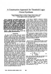
Fig. 1: (a) Example of a BPRT cell that uses a 4 input pixel values. The example shows 4 input weights that are individually connected to separate inputs. (b) An architectural representation of the cell arrangement for a 4 × 4 pixels image; in this configuration, each cell uses 4 analog/digital inputs, has bi-valued weights, and implements image dimensionality reduction.
II. B ILEVEL P ROGRAMMABLE R ESISTANCE T HRESHOLD L OGIC Figure 1a shows the unit processing element in the network which we refer as a modular bilevel programmable resistance memristive threshold logic (BPRT) cell or in short cell. The collection of cells arranged referred to as a single layer forms the proposed network configuration as shown in Fig. 1b. The modular structure of network makes it easy to implement in hardware. The parameters of proposed BPRT cells in Fig. 1b are weights wi (i = 1, 2, ....., N ) and a constant weight w0 . The weights w1 through wN are configured dynamically, using the reference inputs xi . The weighted summation of inputs xi is denoted as xo , while the threshold logic implemented using a logistic function results in a binary output xout . The reference pixel inputs xi from a reference sample Xr is used for setting wi , and results in a binary output value of 1V . When a test pixel xt is applied to the cell, the binary output value would change from 1V to 0V if dissimilar, but will remain at 1V if similar. The proposed cell is essentially a similarity calculator and performs a binary decision oriented pattern matching. It can be noted that, although in principle it may seem somewhat similar to some of the early hard-threshold neuron models, the proposed cell is conceptually and implementation wise different from the conventional threshold logic. In addition, the proposed logic can be realised as a hardware circuit with the weights translated as conductance (i.e. conductance of a memristor) for a potential divider and the threshold translated to an logic inverter as shown in Fig. 1a. The Fig. 1b shows the block wise arrangement of inputs for processing by the BRT cells. Let C be a cell in the arrangement with weight (conductance) values w = {w1 , w2 , ..., wn } and the corresponding inputs x = {x1 , x2 , ..., xn }. Each of the weights wi (1 ≤ i ≤ n) of C is set to either high wH or low wL as follows: ( wH if xi > xa wi = (1) wL otherwise where xa is the average of the normalized pixel values in the input frame and is calculated as xa =
n 1P xi . n i=1
It is not practical or general to use Eq. (1) for setting bilevel weights as in practice it is difficult to implement an ideal inverter logic. An alternative approach to express the same idea of setting the wi to bilevel weight values using generalised wH logistic functions. The generalised logistic function with respect to weights can be expressed as: wi = 1+be cxi + wL . The wH −1 value of c is obtained by equating this to 2 + wL and xi = xa . This results in c = x log b and the equation for setting the a wH weights becomes: w i = + wL . The output voltage x 0 of the weighted part in the cell with n inputs is given by: −xi logb 1+be xa Pn i=1 xi wi Pn x0 = . The threshold output of the cell can be conceptually expressed as: wo + i=1 wi ( 1V if x0 < ta xout = (2) 0V otherwise where, ta is the logistic threshold. A more realistic that calculates xout can be represented as: xout =
xout = where, β =
logb PN . ta [w0 + i=1 wi ]
− xo logb 1 ta
1+b1 e
Substituting the logistic equations of xo , we obtain the xout as: be−β
b1 e
P
1 + be−β
N i=1
−x o logb 1 ta
.
xi wi
PN i=1
xi wi
(3)
The Eq (3) and its logic counterpart Eq. (2) can be viewed as a transform for local similarity
calculation, that compares a set of reference pixels from a template sample Xr to that of the test pixels originating from a test sample Xt . The template sample pixels are memorised as conductance values wi which are set to bilevel values based on the
IEEE TRANSACTIONS ON VERY LARGE SCALE INTEGRATION (VLSI) SYSTEMS
3
intensity of reference input signals. The test sample does not set the weights, and hence the output of the Eq (3) would only change if the reference pixel intensities are significantly different from the test pixel intensities. Suppose in an image there are M block of pixels that are to be compared. This means there will be M cells, the global similarity sg between the test and PM reference sample image can be obtained by the summation of xout across the sample: sg = 1M j=1 xout (j). a) BRT cell working: Figure 1a, shows the hardware model of a 4-input BRT cell in the network shown in Fig. 1a. In this cell the weights, w1 , w2 , w3 and w4 , will be fixed to wH or wL as per the Eq. (1). For an illustration, consider that the 1 1 values for wH , wL and w0 are conductance 10 μS, 100 mS and 501 mS, which can be obtained by changing the memristance of a memristor. The threshold for the inverter has been set as ta = 0.5V . As per the Eq. (3), if the output of the potential divider part (x0 ) is greater than ta the output of the threshold will be 0V ; otherwise the output will be 1V . Now, take a scenario in which an image is 4×4 pixels and the average of the pixel values of the image is 0.6V which is xa of this network, that means all cells in the network will have the xa value 0.6V. In this case the network contains 4 cells in which each cell will have four inputs as shown in Fig. 1a. Suppose for one cell, the input pixels voltage values are, x1 = 0.2V , x2 = 0.3V , x3 = 0.3V , and x4 = 0.1V . These voltage values are considered as the template pixel values. The weights w1 , w2 , w3 and w4 of the cell will be fixed to wL , wL ,wL and wL by changing the memristance of the corresponding memristor as per the Eq (1). Then the voltage at node x0 = 0.15V , which is smaller than the threshold value of the inverter ta = 0.5V , so the output of the cell becomes 1V . For training the cell, the memristor’s weight need to be set using an additional circuit as given in the Fig. 2. This will avoid the unwanted resistance change in the circuit during the test phase. The switches S1 , S2 and S3 will switch as per the control signal ttr , where ttr is high (switch connected) during training phase. The Opamp is designed using eight MOSFET’s [23], where its area is 31.3μm2 and 16μW power dissipation and is used as a comparator is to enable the proper control of the selection inputs. This circuit can be used in serial or parallel to set the memristance of the memristors in training stage. The possibility of serially training the cells based on pixel values using array switched connections is shown in Fig. 2b.
(a)
(b)
Fig. 2: (a) shows the training circuit required to set memristance to high or low value during training stage taking into account the input voltage of the reference pixel, and (b) shows an array realisation of the circuit for network.
To illustrate the change detection in cell, suppose that there is a significant change in input values (change in pixel intensity) when the next frame input is applied, say x1 = 0.9V , x2 = 0.9V , x3 = 0.8V , and x4 = 1V . In the test stage, the weights remain at the same values as that were set using template image pixels. The voltage at the node x0 will change from 0.15V to 0.6V , which is higher than the threshold value of the inverter and hence the output of the cell will change to 0V . It is to be noted that the change occurred here is a change from dark pixel to light pixel and a change is detected by the cell. However, the change will not get registered if there are only slight variations in the inputs. For example, if the new input values are 0.3V , 0.3V , 0.3V and 0.1V which reflects a small change from the template pixels, then the output of the potential divider becomes 0.16V , which is obviously insufficient for the inverter to change its output. In this sense, it can been said that the output of the cell will only change during significant changes in the input. It is from the test pixel changes that we observe that the cell will detect the changes only from black to white and not the reverse. Table I shows the four input cell properties. TABLE I: Area, power dissipation, leakage power and delay of a four input cell, where wH , wL and w0 are Area (μm2 )
9.66
Power dissipation (μW ) 12.30
Leakage Power (pW )
Operational Speed (M Hz)
12.25
100
1 1 μS, 100 mS 10
and
1 mS 50
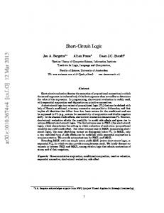
Figure 3 shows the timing behaviour of the proposed 2-input cell having x1 and x2 as the input pixels and xout the output 1 pixel, where the cell is trained to detect dark pixels (0V , 0V ), with both the weights set to wL = 100 mS. The pixel values change in 10ns and the behaviour is shown for a period of 40ns. From the waveform we can see that the cell is able to detect the change from (0V, 0V ) to (1V, 1V ), but it fails to detect the changes from (0V, 0V ) to (0V, 1V ), or (1V, 0V ). This is because the cell is required to detect the changes only if there is a sufficient change in the group of pixels within the image and inherits the ability to discard the random pixel changes from the sensor noise. The proposed work is compared with the benchmark neuromorphic learning chip [14] that target object detection and tracking. In order to do the comparison we have done simulation using similar technology scaling of learning chip [14]. The simulation
IEEE TRANSACTIONS ON VERY LARGE SCALE INTEGRATION (VLSI) SYSTEMS
4
Fig. 3: Waveform showing the response of a 2-input cell, which has trained to (0V ,0V ) input template pixels. We can see that the cell is able to detect the change from (0V ,0V ) to (1V ,1V ) by changing xout to 0V from 1V .
Fig. 4: Effect of change in technology length on a 4 input cell
is performed in SPICE (Simulation Program for Integrated Circuit Emphasis) using feature size of 0.35 μm TSMC (Taiwan Semiconductor Manufacturing Company) process BSIM (Berkeley Short-channel IGFET Model) models and HP memristor model [24]. The results in Table II, show a clear advantage for the proposed method, in terms of performance when compared with the neuromorphic learning chip1 [14]. TABLE II: P ERFORMANCE C OMPARISON BETWEEN A BRT NETWORK OF 32 N EURON C ELL WITH THE L EARNING C HIP IN [14] Parameters Area (μm2 ) Power dissipation (W )
BRT network 309 396μ
Learning Chip [14] 1936 60m
Throughout this paper, we use the non-ideal resistive switching model of memristor reported in [24] for our study with an area of 10nm×10nm and resistances in the range of [106 , 1012 ]Ω, while CMOS circuits use 0.25μm TSMC technology to reflect the practical standard silicon technologies. The estimation of the area is done at the device level only. The reported area of a network were estimated based on the area of a macro model used. Figure 4 shows the effect of change in technology length on the output of a 4-input cell. From the figure we can see that a ± 50nm change in the technology length does not introduce any effective change in the cell response both in case of logic high (1) and logic low (0). Since the physical design of the memristor is not available to simulate, practically we will not be able to check the scalability issues and the response plotted in the Fig. 4 is the simulated results using non-ideal memristor models in SPICE, and realistic CMOS process models. b) Fast Object Detection: In object detection, a template image frame is chosen from the video input and subsequent test image frames are compared with the template frame. We require two parallel BPRT networks in order to detect both light to dark and dark to light pixel intensity changes in the object. This method is shown in the Fig. 5a where each BRT network is shown as a separate modules. Module 1 of the BPRT network is meant for the detection of dark to light pixel intensity changes and module 2 for the light to dark intensity change detection. The resistor weights in the module 1 will be set using the template image pixel and that of module 2 with the inverted template image pixels during the training phase of the network. Each cell in the modules contains 4-inputs, to which 4 input pixel voltages from input images are applied as shown in the Fig. 5a. The resistor values (weights) of each cell is fixed based on the input pixel values, such that each cell in the module is trained to detect any sufficient changes occurring in the input set of pixels. The output of the modules is of size equal to the number of cells as shown in Fig. 5a. These outputs have a value of 1V when the template pixels are applied as the inputs. The output of two modules will be combined pixel-wise using AND gates in order to merge similarity detection results of both dark to white and white to dark changes. The processing speed of few megahertz would mean that more than 106 images can be processed in 1 second. Even when delay of the training elements are taken into account this would still be more than sufficient to deal with high frame rates of a camera. In practical terms, as the frame rates of the camera are still limited to a few tens to hundreds of frames per second, the proposed object detection would not have issues with continuous update of the memristors. However, in future when extremely 1
The results compared are specific to the cell level. The board level performance is not compared as they would be different in application and need.
IEEE TRANSACTIONS ON VERY LARGE SCALE INTEGRATION (VLSI) SYSTEMS
5
Fig. 5: (a) Training of a BRT network for object detection with an input image of size 4 x 4 pixels. Module 1 has been trained with original input image and Module 2 has been trained with the inverted input image. (b) A new image is passed through the trained network resulting in change detection at the output.
higher frame rates are required, the improvement in operating speeds would be required, that is largely dependent on the operation speed of the operational amplifiers and CMOS invertors in the circuit. When the test frames are applied, if there is any sufficient change in the set of pixel values, the output of that particular cell will change from 1V to 0V . This behaviour of the cell is shown in the Fig. 5b. Here the image is different from the trained template image. It has both dark to white and white to dark changes and both this changes are detected by the corresponding modules. In addition, it can be seen that the values of the output in the detection of moving object has been recorded by changing the corresponding cell output to 0V. When combining the module output values, we are able to detect the total changes in the image. This is shown in the output image as two dark pixels. The unchanged values are the static background and the changes detected are the objects. From, Fig. 5a and Fig. 5b it is clear that since the size of cell is 2 × 2, the size of the output image will be reduced to N × N , where N × N is the input image size. 2 2 TABLE III: C OMPARISON OF P ERFORMANCE PAR AMETERS FOR T WO D IFFERENT BRT N ETWORKS . Performance parameter Area Power dissipation Leakage power Operational speed
(a)
Value (4×4 pixels) 193μm2 103μW 245pW 100M Hz
Value (352×288 pixels) 1.22mm2 0.65W 1.55μW 100M Hz
(b)
Fig. 6: The illustration showing (a) the template image pixels and (b) the test image with object pixels detected.
IEEE TRANSACTIONS ON VERY LARGE SCALE INTEGRATION (VLSI) SYSTEMS
6
TABLE IV: T HE P ERFORMANCE R ESU LTS OF THE P ROPOSED T EC HNIQUE Database object label ViSOR PETS 2000 CDVP SPEVI
Sensitivity Specificity False (%) (%) positive (%) 92.3 96.8 3.2 100 100 0 89.8 92.4 7.6 98.3 100 0
False negative (%)
Youden’s Index
Precision (%)
7.7 0 10.2 1.7
0.8906 1 0.8218 0.9833
99 100 92.2 100
Positive likelihood 28.6 ∞ 11.8 ∞
Negative likelihood 0.1 0 0.1 0
F-measure (%)
Accuracy (%)
95.5 100 91 99.2
93.3 100 91.1 99.2
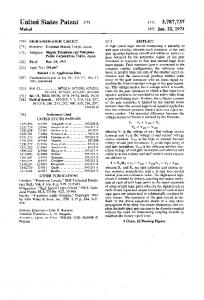
Figure 6 shows the illustrative result of moving object detection using the proposed cells. The simulation shown in Fig. 6 has been done using an array of 4-input cells and with an input frame size of 352 × 288 pixels. The values of the performance parameters (for the input frame size of 352 × 288 pixels) are given in Table III. The network gives an output at a reduced dimension of 176 × 144 pixels. We used the macro-model cells in Fig. 1 to simulate the object detection in 352 × 288 pixels. The pixels were processed within SPICE simulation environment through reading image frames from the benchmark object detection databases (ViSOR, PETS 2000, CDVP, and SPEVI databases). The binary changes detected in the output are then plotted back on the original image for display purposes. The template image at time t0 (Fig. 6a) is the first frame in the video and does not have any moving objects, while at in a subsequent frame at t1 objects (Fig. 6b) enter the scene and are detected as shown by the red colored pixels. The results are reported using ViSOR, PETS 2000, CDVP, and SPEVI databases. The performance values on object tracking tests across the databases result in an average F-score of 96.4%, accuracy of 95.9%, Youden’s index of 0.924, sensitivity of 95.6%, and specificity of 97.3%. Table IV shows the breakup of these results for the databases. Figure 7 shows the receiver operator characteristic of the object detection on the four databases using our proposed cell. The plot has been generated based on the amount of object blobs that have been correctly classified. Although objects are detected in all the frames, those that are difficult to recognise due to overlap with other objects in the same frame are considered to be not detected to make it realisable in practical object tracking tasks.
(a)
(b)
(c)
(d)
Fig. 7: A graphical illustration of performance of the proposed method in realistic object detection situations: (a), (b), (c), and (d) show the receiver operator characteristics, along with a sample image frame with obtained detections for ViSOR, PETS 2000, CDVP and SPEVI databases. The boundaries shown are for illustration purpose.
There exists low-power programmable circuits mimicking neural behaviour [25], [26] that can be used for object detection applications. However, any objective comparison between the proposed cell and those of the like in neuron-synapse in [25] is difficult with different technologies without reporting the power and area specific at the cell level. The classification part in similar works assumes the knowledge of gallery that can be understood as a offline matching method. In contrast, the proposed method produces templates on the fly (online processing) and the detection of objects are done on the incoming images without storing the templates, rather is encoded in the network of the cells. III. C ONCLUSION A programmable memristive threshold logic circuit for moving object detection was presented in this paper. An important advantage of the method discussed is that it can support an implementation targeted at high speed imaging. The hardware nature of the cell architecture makes it an alternative to algorithmic approaches and highly attractive to the practical utilisation of high frame rates that could lead to near-continuous real-time object tracking, and even surpass human object tracking ability. The presented logic provides a framework to implement brain like logic in a memory and learning driven detection of multiple objects. In terms of hardware implementation, this needs memristor like devices that can do large number of cycles, smaller area and long data retention time which may be made possible with emerging memory technologies. A truly reconfigurable and dynamic cell for multiple object detection, tracking and recognition in high resolution and high speed videos is a topic for further research, that may have a significant impact on the way object detection in real-time is implemented in hardware. R EFERENCES [1] A. P. Shon, R. P. N. Rao, and T. J. Sejnowski, “Motion detection and prediction through spike-timing dependent plasticity,” Network, vol. 15, no. 3, pp. 179–198, 2004.
IEEE TRANSACTIONS ON VERY LARGE SCALE INTEGRATION (VLSI) SYSTEMS
7
[2] S. Grossberg, J. Leveille, and M. Versace, “How do object reference frames and motion vector decomposition emerge in laminar cortical circuits?” Attention, Perception, & Psychophysics, vol. 73, pp. 1147–1170, 2011. [3] V.Salari and I. Sethi, “Feature point correspondence in the presence of occlusion,” IEEE Transactions on Pattern Analysis and Machine Intelligence, vol. 12, no. 1, pp. 87–91, 1990. [4] C. M.Reinders and E.Backer, “Resolving motion correspondence for densely moving points,” IEEE Transaction for pattern analysis in machine intelligence, vol. 23, no. 1, pp. 54–72, 2001. [5] T.Broida and R.Chellapa, “Estimation of object motion parameters from noisy images,” IEEE Transaction for pattern analysis in machine intelligence, vol. 8, no. 1, pp. 90–99, 1986. [6] S. Avidan, “Support vector tracking,” in IEEE Transactions on Pattern Analysis and Machine Intelligence, vol. 26, no. 8, pp. 1064–1072, 2001. [7] D. Comaniciu, V. Ramesh, and P. Meer, “Kernal-based object tracking,” IEEE Transactions on Pattern Analysis and Machine Intelligence, vol. 25, pp. 564–575, 2003. [8] A. Blake and M. Isard, Active Contours:The Application of Techniques from Graphics, Vision, Control Theory and Statistics to Visual Tracking of Shapes in Motion. Springer, 2000. [9] M. Bertalmio, G. Sapiro, and G. Randall, “Morphing active contours,” IEEE Transactions on Pattern Analysis and Machine Intelligence, vol. 22, no. 7, pp. 733–737, 2000. [10] J. Lu, S. Young, I. Arel, and J. Holleman, “30.10 a 1tops/w analog deep machine-learning engine with floating-gate storage in 0.13μm cmos,” in Solid-State Circuits Conference Digest of Technical Papers (ISSCC), 2014 IEEE International. IEEE, 2014, pp. 504–505. [11] J. Lu., S. Young, I. Arel, and J. Holleman, “An analog online clustering circuit in 130nm cmos,” in Solid-State Circuits Conference (A-SSCC), 2013 IEEE Asian. IEEE, 2013, pp. 177–180. [12] R. Aguilar-Ponce, J. Tessier, C. Emmela, A. Baker, J. Das, J. Tecpanecatl-Xihuitl, A. Kumar, and M. Bayoumi, “Real-time vlsi architecture for detection of moving object using wronskian determinant,” in Circuits and Systems, 2005. 48th Midwest Symposium on. IEEE, 2005, pp. 875–878. [13] C. Koch and B. Mathur, “Neuromorphic vision chips,” Spectrum, IEEE, vol. 33, no. 5, pp. 38–46, 1996. ´ ´ ˜ [14] R. Serrano-Gotarredona, M. Oster, P. Lichtsteiner, A. Linares-Barranco, R. Paz-Vicente, F. Gomez-Rodrıguez, L. Camunas-Mesa, R. Berner, M. Rivas´ Perez, T. Delbruck et al., “Caviar: A 45k neuron, 5m synapse, 12g connects/s aer hardware sensory–processing–learning–actuating system for high-speed visual object recognition and tracking,” Neural Networks, IEEE Transactions on, vol. 20, no. 9, pp. 1417–1438, 2009. [15] G. Indiveri, “Neuromorphic analog vlsi sensor for visual tracking: Circuits and application examples,” Circuits and Systems II: Analog and Digital Signal Processing, IEEE Transactions on, vol. 46, no. 11, pp. 1337–1347, 1999. [16] C. Christodoulou, G. Bugmann, and T. G. Clarkson, “A spiking neuron model: applications and learning,” Neural networks, vol. 15, no. 7, pp. 891–908, 2002. [17] R. J. Vogelstein, F. Tenore, L. Guevremont, R. Etienne-Cummings, and V. K. Mushahwar, “A silicon central pattern generator controls locomotion in vivo,” Biomedical Circuits and Systems, IEEE Transactions on, vol. 2, no. 3, pp. 212–222, 2008. [18] S. Yasukawa, H. Okuno, S. Kameda, and T. Yagi, “High-speed multiple spatial band-pass filtering using a resistive network,” in Mechatronics and Automation (ICMA), 2013 IEEE International Conference on. IEEE, 2013, pp. 1299–1304. [19] A. B. Torralba and J. Herault, “An efficient neuromorphic analog network for motion estimation,” Circuits and Systems I: Fundamental Theory and Applications, IEEE Transactions on, vol. 46, no. 2, pp. 269–280, 1999. [20] G. Indiveri, P. Oswald, and J. Kramer, “An adaptive visual tracking sensor with a hysteretic winner-take-all network,” in Circuits and Systems, 2002. ISCAS 2002. IEEE International Symposium on, vol. 2. IEEE, 2002, pp. II–324. [21] A. Fish, A. Spivakovsky, A. Golberg, and O. Yadid-Pecht, “Vlsi sensor for multiple targets detection and tracking,” in Electronics, Circuits and Systems, 2004. ICECS 2004. Proceedings of the 2004 11th IEEE International Conference on. IEEE, 2004, pp. 543–546. [22] T. Serrano-Gotarredona, T. Masquelier, T. Prodromakis, G. Indiveri, and B. Linares-Barranco, “Stdp and stdp variations with memristors for spiking neuromorphic learning systems,” Frontiers in neuroscience, vol. 7, no. 2, February 2013. [23] P. E. Allen, D. R. Holberg, P. E. Allen, and P. Allen, CMOS analog circuit design. Holt, Rinehart and Winston New York, 1987. [24] D. B. Strukov, G. S. Snider, D. R. Stewart, and R. S. Williams, “The missing memristor found,” Nature, vol. 453, no. 7191, pp. 80–83, 2008. [25] M. Sharad, C. Augustine, G. Panagopoulos, and K. Roy, “Spin based neuron-synapse module for ultra low power programmable computational networks,” in Neural Networks (IJCNN), The 2012 International Joint Conference on. IEEE, 2012, pp. 1–7. [26] M. Sharad., C. Augustine, G. Panagopoulos, and K. Roy, “Ultra low energy analog image processing using spin based neurons,” in Nanoscale Architectures (NANOARCH), 2012 IEEE/ACM International Symposium on. IEEE, 2012, pp. 211–217.