Telecommunications Software Systems Group (TSSG). Waterford ... and implementation of a federated billing and accounting solution for inter- enterprise ...
The Rational Unified Process (RUP) [8] is used as a partial template to integrate the following modelling techniques: use case modelling, business process.
Jan 11, 2016 - false positive rate (FPR) reported by M on labeled data. ese values are important, because they give us a feeling of how well M would perform if ...
Jan 11, 2016 - ransomware [14]) and devising more e cient techniques to deliver malicious payloads to victim computers (
tion of a mutant shows its output to have a similar range ... and section VIII presents our conclusions. II. ... Faults exist as incorrect steps .... gave a mutation score of 97.18% on the original set [11][14]. .... as integers in the same way there
how Aspect Oriented Programming (AOP) can be used to modularize service .....
Component software: Beyond Object-oriented programming. Addison-. Wesley ...
Recently genetic programming (GP) has started to show its promise by ... netic
Algorithms + Data Structures = Evolution Programs as the title of his book.
Yuan Yaoi, Paolo Frasconi2, and Massimiliano Pontil3'i. 1 Department of
Mathematics, City University of Hong Kong, Hong Kong. 2 Department of
Systems and ...
Jan 11, 2016 - validate this approach via a large-scale analysis on real-world data. ...... associated with the graphs a
the laboratory setting, opening a separate port for SmartFrog (given the ... if the SmartFrog daemon needs to run as a privileged user such as ârootâ, as is the.
Oct 28, 2013 ... Google Platform Characteristics. • 100s to 1000s of PCs in cluster. • Cheap,
commodity parts in PCs. • Many modes of failure for each PC:.
Model Projection, Extended Finite State Machines, Slicing. 1. INTRODUCTION ... The design of models typically occurs earlier in the overall de- velopment ...
Nov 4, 2013 ... Pinocchio Coin: Building Zerocoin from a Succinct. Pairing-based Proof System.
George Danezis. Microsoft Research. Cambridge, UK.
INTRODUCTION TO THE DESIGN AND ANALYSIS OF. ALGORITHMS - Anany
Levitin (Pearson International) Clear and well written and about the right level.
Jul 23, 2010 - Modelling of Spiking Neurons Using GPUs," Application-Specific Systems, ... âR. Stewart and W. Bair, "Spiking neural network simulation: ...
reverse engineering technology of the 1990s. Keywords. Software engineering, reverse engineering, data reverse en- gineering, program understanding ...
Objective: In order to uncover the latent cluster- ing of mobile apps in app stores, we propose a novel tech- nique that measures app similarity based on claimed ...
void f(char a[ELEMCOUNT]) void f(char ...... Rothermel. An empirical study of ... In Raymond T. Ng, Peter A.; Ramamoorthy, C.V.; Seifert, Laurence C.; Yeh, ed-.
Chapter 11, in Genetic Programming Theory and Practise, Rick L. Riolo and Bill
... solutions, evolutionary search is effective at finding them (Section 11.6).
transforming into monstrous forms as seen in some movies. On its own ... enabled us to produce humanoid robots with similar levels of articulation as humans.
Loyola University Maryland. Baltimore, MD, USA [email protected]. ABSTRACT. While clone detection and classification research for textual source.
scale e-business solutions that fulfill business goals within a short time-to- .... must collaborate and coordinate its activities with other components in a com-.
homocysteine. This process involves the betaine- homocysteine methyltransferase (BHMT)'. With the identification of the polyinorphism of. MTHFR, dietary and ...
... form 20 October 2005). The base-line modeling concept presented in this work is based on the assumption of .... 4 6 log Kow. 8. 10. 12. 14. 16 log BCF = 3,699. *. * log BCF. DAN - 7. XXXX. *. ****. HE+. XXX ..... [8] M.Th.M. Tulp, O. Hutzinger.
Peter T. Kirstein, P. O'Hanlon, K. Carlberg, P. Gevros, K. Hasler. University College ...... [mars00a] W Marshall and M Banfield, âAn architecture for application ...
The RadioActive Networking Architecture Peter T. Kirstein, P. O’Hanlon, K. Carlberg, P. Gevros, K. Hasler University College London
Abstract This paper describes the activities in Application Level Active Networks (ALAN) under the DARPA-funded RADIOACTIVE Project; this is closely related to work carried out under a European Commission project ANDROID. The ALAN infrastructure was developed mainly under other projects; it is summarized here mainly for background. The version used here relies on separate Active Applications driven by policies – with the policies expressed in XML. There are two principal applications carried through in this project – adaptation of multicast, multimedia conferencing tools (M-Bone) and Virtual Private Networks (VPNs). The former were developed in other projects; the latter derives from the X-Bone overlay networks of ISI. It is an important aspect of the project that the final activity all works in the context of IPv6. The paper describes the measures that were required to make the applications into ALAN ones, and the problems encountered in moving all the components to work in the IPv6 environment.
1 1.1
Introduction Preface
The basic architecture described in this paper is not new, or even original to the authors of this paper. It is based heavily on the work of Marshall et al [mars99], [mars00]. Another part, that on policies, is based on the work of Prnjat et al [prnj01]. However both the RADIOACTIVE project [kirst01], described here, and the ANDROID project [carl01] use the same infrastructure. For this reason, here we use the same description as in the references.
1.2
Programmable Networks
User expectations of the range and quality of Internet services are growing rapidly and are outstripping the ability of the infrastructure to deliver. Flexibility and responsiveness are two key aspects that must be addressed before the gap between potential and reality can start to be
closed. Essentially this requires that the network becomes a programmable infrastructure. There are two main approaches to this problem: Active Networking (AN) is based on the dynamic deployment of new services. It has its roots in the Defense Advanced Research Projects Agency (DARPA) projects; the field was surveyed by Tennenhouse in 1997 [tenn97]. The main emphasis is on enhancing the functionality of Internet Protocol (IP) networks where a number of problems have been identified, related to the “end-to-end” model in which computation is performed predominantly at network endpoints. The role of computation in the network is restricted to simple header processing for routing user data, which is transported opaquely. This approach has worked very well in the development of the Internet; however some applications can be greatly enhanced by exploiting the characteristics of the network to optimize the way user data is processed on intermediate network nodes. Several intermediate devices already require specific computational capabilities. Examples include devices supporting application-specific functions such as packet filtering, differentiated Quality of Service, tunneling, intrusion detection and security. In addition, Network Address Translators (NAT) and Application Level Gateways (ALG) are used to provide end-to-end transparency for applications across multiple network domains. The IETF Network Working Group has identified the need for such intermediate devices (termed middle-boxes) and the importance of managing their operations [midd01]. There are two main approaches to active networking, discrete and capsule. The discrete approach separates the mechanism for injecting programs into a programmable node from the actual processing of packets as they flow through a node, with a separate mechanism for each function. Users send a program to a node and this program would then be stored at the node. When a packet arrives at the node, its header is examined and a program is used to process the packet. The program actively processes the packet, possibly changing its contents, or the resources associated with a packet. The capsule approach leads to a more dynamic form of active network. Each packet in such a network contains both data and a program fragment (of at least one instruction) that may include embedded data. The term
capsule is used to describe these new types of packets. When a capsule arrives at an active node, its contents are processed using the program in the capsule. The traditional router or switch, which is responsible for routing and header processing, is replaced by an active node that consists of three other major components: a code loading mechanism, a transient execution environment, and a more permanent storage area. Much of the DARPA work in active networking [darpa] has concentrated on the capsule approach; this is shown by most of the papers presented at this conference. In the ANDROID and RADIOACTIVE projects, we adopt a discrete approach to active networking. Loading of programs can be more easily controlled, and the functionality can be more sophisticated without the size restriction imposed by the size of the capsule. A further distinction can be drawn between active networks and active services. Programmability can be offered at different levels in the OSI protocol stack. Programmability at lower layers (e.g. transport or network) is traditionally regarded as active networking. Performance is potentially high although flexibility is limited, particularly as concerns over security and safety are very strong. Active networking is concerned with providing user control over the routing and forwarding characteristics of the network. Programmability at higher levels (e.g. application) does not directly affect the operation of the lower layers and deployment should be faster as it can be incremental. Active nodes operating at the application layer are end systems (c.f. servers and proxies located within the network) and provide active services, which can perform essentially any applicationspecific processing on user information flows. There are several problems with putting all such capability in the router. First, it is much easier to deploy experimental code in near operational conditions at the user level; this is because a server can be optimized to run this style of activity. By contrast most routers require special hardware support to operate efficiently at high load. Router vendors are loath to put any hardware support in routers until the relevant functionality has been proved essential. Moreover it is easier to allow non-active traffic to continue to pass at full speed in systems where the active code is run in a separate server. Finally, it is easier to protect at least non-active traffic from defective experimental code if carried out in a server. Most of this paper concentrates on the Active Server environment. Performance is often regarded as a problem in application layer active networking since data always passes up and down a full protocol stack. However, processing power or specialized computing resources can be made available much more easily at the application layer than within a network-level service such as a router.
1.3
Active Networking: Node-OS
Members of the DARPA active network program [darpa01] have been developing an architectural framework of active networking. A node operating system, called Node-OS [peter99], represents the lowest level of the framework. Encapsulation techniques based on an active network encapsulation protocol (ANEP) [alex97] support the employment of multiple execution environments within a single active node: ANEP defines an encapsulation format allowing packets to be routed through multiple execution environments coexisting on the same physical nodes. The complete architecture is described in [calv99]. Portability of execution environments across different types of physical node is achieved via a common, standard interface to Node-OS. This interface defines four programmable node abstractions: threads, memory, channels and flows. Threads, memory and channels abstract computation, storage and communication capacity used by execution environments, whereas flows abstract user data-paths with security, authentication and admission control facilities. The architectural framework for active networking is being implemented in the ABONE test bed [brad01], allowing researchers to prototype new active architectures.
1.4
Active Services
The Active Services approach attempts to preserve the routing and forwarding semantics of the Internet architecture by restricting computation to the application layer. The active networking approach raises a number of problems associated with safety and security, for example. Active services represent a more pragmatic approach to providing network programmability that is compatible with existing systems. The possibility of incremental deployment in the Internet makes active services a realistic short-term option. An early example of the active services approach is described by Amir [amir98]. In ANDROID and RADIOACTIVE, application layer programmability is based on work done first by Fry and Ghosh [fry99] while the latter was at UCL, and then continued from University of Technology, Sydney [ghos00]. The defining characteristic of an active network is the ability for users to load software components dynamically, without explicit reference to any third party. This can encompass systems with markedly different capabilities. In the ANDROID project [fish01], the business model; distinguishes between two flavors of “activeness”; active routers and active servers. These have different restrictions on control and different degrees of flexibility. This distinction is discussed in more detail in the paper and in the references. In the RADIOACTIVE project, we
consider only active servers. This simplifies the architecture that we need to describe here. There are several distinct roles in the business model described in [fish01]. Each role may be played by any number of businesses, even within the same business scenario; these roles include the User, Active Server operator, component vendor, service integrator and service provider. One reason for the architecture developed is to provide for the separation of these roles.
2 2.1
An Architecture For Application Layer Active Networking With Active Servers The ALAN Architecture
Application level active network (ALAN) [Fry99] provides an environment in which developers can engineer applications through the network by utilizing platforms on which 3rd party software can be dynamically loaded and run [Mars99]. The ALAN system consists of active nodes that are located in the existing Internet. These nodes run an Execution Environment for Proxylets (EEP). Proxylets are Active Applications which are downloaded to the EEP and executed on behalf of users. Those applications provide functionalities that enhance the level of service or introduce new services to the final user. Endto-end active services are provided by one or more EEPs executing one or more proxylets. Messaging uses XML [XML01a, XML01b] which is transported over HTTP [Mars00].
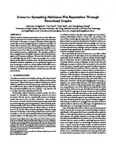
management for primary issues of starting and maintaining the services and on resource management. In the ANDROID scenario active nodes are distinguished in two categories: the active routers and the active servers (Figure 1). The active router provides an execution environment that runs dynamically loaded routing software components. Those components offer to users customized routing tables according to user defined policies. Flexibility is restricted by allowing users to provide only configuration policies for components that are selected by the router operators. The active server, the equivalent of the ALAN EEP, is the second type of active node that offers more flexibility to users. It can be considered as an end system with a full protocol stack. It also provides an execution environment capable of running user-provided processes that are unrestricted above the transport layer [Mars99a]. Multiple EEPs are allowed to run on each active server. Each EEP is allowed to run one or more proxylets. In our current implementation, FunnelWeb, the EEP runs as a Java Virtual Machine (JVM), with each proxylet running in a separately spawned JVM. Active server security and resources (consumed by the proxylets) are managed locally. Proxylet thread resource consumption is managed by application providers or the users and is out of the scope of the ANDROID project. Restricting management system capability from the thread to proxylet level is done since in the business environment in question proxylets are considered as self-contained, user-specified services.
2.2
Radioactive Servers Architecture
The RADIOACTIVE project is funded by the DARPA Active Network Program [darpa]. We have already discussed that the ANDROID Project uses both Active Routers and Active Servers. That project involves many organizations in addition to UCL; the Active Router comes from another company 6WIND [6wind01]. In RADIOACTIVE we wish to have a system that can be deployed not only by UCL, but could be deployed if necessary on the A-BONE network, which is being developed also under the DARPA Active Network Program to provide a test bed on which the projects funded under the program could be deployed. This deployment would not be possible if it was necessary to deploy a proprietary box in order to experiment with a larger number of nodes than is available to UCL. Figure 1 Application layer active network architecture These concepts are being developed further in the ANDROID project, which focuses on the development of a scalable, lightweight management infrastructure for the ALAN-based active networks. The ANDROID system is an event driven, policy enabled management system [Mars00]. The focus of ANDROID is on developing the
As a result, in the RADIOACTIVE Project, we have restricted ourselves to working with Active Servers – using the EEPs of Section 2.1. The Active Server can offer dynamic programmability. It runs a full protocol stack and so is logically an end system, although it may be physically associated with a router and function as a network intermediary from the viewpoint of users. An important feature of active servers is that any undesirable operation will have limited consequences. The control that
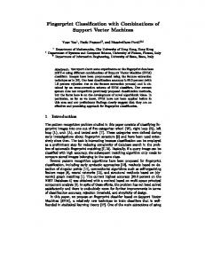
can be delegated to general users can be much greater than in an active router. An active server provides execution environments (Server-EE), which provide the capability of running user-provided code, essentially unrestricted, above the transport layer. This can be achieved safely since each customer can in principle be provided with a dedicated active server. An example of the structure of an EEP is shown in Fig. 2.
Control Interface Node Monitoring & Management
AA
PM
AA
PM
AA
PM
EEP Core
Figure 2 FunnelWeb Architecture In Fig. 2, the Active Applications (AAs) are the Proxylets mentioned earlier; they are controlled by Policy Modules (PMs). In general there could be multiple kinds of server EE’s available, with different component interfaces so that as few restrictions as possible are placed on the users of the active infrastructure. However in RADIOACTIVE, the Proxylets are all written in pure JAVA, and run over the FunnelWeb Execution Environment (EE) mentioned earlier – with each instance of FunnelWeb running in a separate JAVA Virtual Machine (JVM). A node monitoring/management system can control the EEP, and each AA has a well-defined control Interface. The EEP is made as part of the system of Fig. 3 which shows the relevant portion of Fig. 1 for the RADIOACTIVE Project. Here we are concerned only with Active Services at the edges of the Internet. The EEP is the Active Server from Fig. 1, the architecture of which is shown in Fig. 2. End-to-end applications are either between two Clients or between a Client and a Server. The Active Service proxylets of Fig, 2 are fetched dynamically from the Active Applications (AA) Depository, and the Policy Modules from the Policy Depository of Fig. 3. FunnelWeb ensures that these modules can be loaded dynamically and bound together. Of course one Active Service may require several AA proxylets and Policy Modules. Moreover, the AA proxylet may be generic, while the policy module is related to the specific user request – or organization request; the latter case might apply, for example, if the application is the set up of a dynamic Virtual Private Network (VPN).
Node Monitoring & Management AA Depository
Client
EEP Edge Network
Policy Depository
Internet Edge Router
Server
Figure 3 System for Running Active Services It is desirable that packets that do not require active processing pass through at full speed; hence packets requiring active processing need to be marked in some way to allow correct handling by the routers. The effect of this marking is to identify the correct routing table within the router (ER) to be selected. This allows the discrimination of active and conventional packets and the selection of an active server. Routing to the active server can either be direct (treating it as an end system), or via a local server listening on the anycast address in the packet. In the absence of an active router, it is possible to structure the routing tables in the Edge Router(s) so that all packets that might require active processing are directed to the Active Server(s). The routing tables on the Edge Routers are then adjusted so packets originating from the Active Server are directed to the correct address. With IP, the marking of packets and their recognition in the router require some changes in the router itself so that packets may be routed based on a flow identifier or multi-field classification. In parallel, we are exploring in the relevant IETF working group for a standard format to deal with packets destined for active processing. Once the relevant packets have been sent to the active server, it must identify the nature of the processing that should be applied to the packet, selecting or loading the appropriate proxylet and delivering the packet for processing. Proxylet instances running in Server-EEs will have a range of lifetimes. In particular, some will be longlived and support multiple users. In these cases, anycast routing to proxylets might be appropriate and could be achieved by the relevant routing table.
3 3.1
Management, Policy Description And Syntax Policy Schema
Management in a distributed system on the scale of the Internet must address support for multiple domains, making independent decisions and using a wide range of technologies. Centralized control will not be possible and the response of the system will be the result of a collection of autonomous actions. There is however the need to exchange management information, for monitoring and control, between interacting systems. In order to achieve this we require common information models or at least common information syntax. It is not reasonable to expect that a single policy language will be universally accepted so instead we focus on an approach that is intended to facilitate exchange of management information between different systems. This is achieved by identifying a restricted set of common information, much of which is optional, and allowing flexible extensions to accommodate a wide range of specific applications. The schemas described in this section are used within ANDROID to provide a unified management framework.
3.2
In this way, problems of heterogeneity and scale can be handled by a “divide-and-conquer” approach, and speed of response can be achieved by resolving problems locally.
Policies and Events
In an automated, distributed approach to management, decision making must be made based on locally available information and according to a set of rules. These rules, which govern choices in the behavior of the system, are termed policies [damn00]. Policies allow the users of a system to specify the behavior they want it to exhibit. Policies allow selections to be made from a range of options provided by the designer of the policy-controlled component. These selections can be specified in terms of a set of conditions with associated actions. When a policy is triggered, conditions involving locally available information can be evaluated and the appropriate actions initiated. This allows flexibility to be built into a system by supporting a range of different behaviors rather than hard-coding a particular behavior – essentially fixing the policy at design-time rather than run-time. Policies provide a mechanism to control system components. Autonomous decision making also requires state information to be shared with other components so that a picture of the local conditions can be built up. An event-based mechanism is appropriate in a loosely coupled decentralized system. A distributed approach based on policies and events allows considerable flexibility in management [Marsh01]. Management system components can be organized in a hierarchy, each with a set of policies controlling its decision making. Management issues can be resolved at as low a level as possible, only referring to a higher level when necessary.
3.3
Management Information
Support for heterogeneous systems makes it essential that events (monitoring information) and policies (control information) are represented in a platform neutral way. XML has recently emerged as a widely accepted way of representing and exchanging structured information. Its principal technical strengths are that it has a sufficiently strict syntax to permit automated validation and processing of information in an unambiguous way, and that it has a text-based representation that imposes few restrictions on network technology or protocols. It allows users to define representations specific to their own applications with a well-defined syntax. Translation between different XML representations is also straightforward using XSLT [XSLT01] reducing the requirement for strong standardization. XML does not, of course, assist in understanding the meaning of the information represented. The use of XML as an intermediate representation still allows policies to be developed using any existing approach. Distributed systems based on technologies such as CORBA, EJB or COM can use mechanisms and protocols optimized for these environments. A welldefined mapping of management information to an XMLbased representation can assist considerably in interworking between systems.
3.4
Policy Syntax
The overall structure of a policy is shown in Figure 4. The general approach is consistent with [damn00]. A policy is written to be interpreted by a subject, which is then expected to perform specified actions on targets, possibly dependent on some conditions. The top-level policy specification consists of six elements. The creator element allows the origin of a policy to be established. This policy specification is intended to be applicable in an environment where there are multiple points of control. Components should be able to accept control from users with different privileges. The administrator of a router, for example, will have ultimate control of its configuration, including the permitted extent of control by other users. End users may be allowed to control the way the router behaves for their own traffic.
to result in the generation of a single event, which then triggers an appropriate policy. A system that provides this functionality is described in [Nata01]. If a trigger element is not present, the policy is assumed to be activated as soon as received. This approach can be used in systems, which are not based on events. Triggerless policies can be used, for example, to effect immediate configuration changes that control subsequent behavior.
Figure 4 Schematic of Policy Syntax The info element contains most of the information about the policy that is not directly related to the policy rules. It includes a globally unique identifier for the policy and an indication of the modality of the policy (positive authorization – what the subject may do, negative authorization – what the subject may not do, obligation – what the subject must do, or refrain – what the subject should not do). The intention is that the modality should not be mixed within a single policy. The general policy handling components of the management system, which have no detailed knowledge of the specific rules contained in the policy, may then take advantage of this classification. It may also contain a textual description of the policy. The creation time, start time and expiry time of the policy can also be specified. Finally, a list of policies replaced by the current policy may be specified. Policies are considered to be immutable so different versions are not possible.
Every policy includes one or more actions elements. These specify the behavior that should result from the triggering of the policy. Each actions element contains an optional condition expression and a set of strings specifying actions to be taken on particular target components. These actions can use the open content features of XML schema to allow tags appropriate to any particular system to be included in a policy instance. All that is required is for the creator of the policy and the system on which the action is to be taken to agree on the syntax and semantics of the action. For an example of a polcy see Appendix A.
3.5
Events
The structure of an event is shown in Figure 5 Its purpose is to provide sufficient information to allow generic components to be used in the distribution of events to all interested components but also to allow any additional information to be included to support specific circumstances. An event following the syntax specified here may be generated either directly or by an XMLaware component (such as ANDROID security and resource managers) or by a special monitoring component that obtains information using some other mechanism.
The sender element identifies the forwarding path the policy has taken. This information could be used as a check that the policy has followed an expected route, or to establish that the policy has already been received by other parts of the system. This element may be modified between creation and receipt of the policy and would therefore not be subject to digital signing. The subject element identifies those entities in the system which are expected to respond to a policy. Identification of these entities is done by role. This is important so that a policy can refer to entities that are not present or not known at the time of creation. The optional trigger element relates an event (via its unique event type identifier) to the policies that are supposed to handle it. When an event is detected, relevant policies must be activated. It is assumed that a policy is triggered by a single event. Correlation of events (aggregation, sequences, threshold rates etc.) is assumed
Figure 5 Event Specification
The top-level event specification consists of seven elements. Each event type has a unique event-id, a globally unique string that may be used to trigger appropriate policies. Typically this will be used as a key into a store of policies. The time element identifies when the event occurred while the optional time-to-live element specifies for how long the event is relevant. Use of this information can allow certain events to be discarded if not handled in time, limiting unnecessary management traffic. The source element identifies where the event originated. The sequence element is an integer, which is incremented with each event produced from a particular source. This can support partial ordering of events, which may be useful, for example, in correlation of events from a single source. The optional information element is a text string intended to be read by people rather than processed automatically. The data element has an open content model and allows any well-formed XML to be included. This is where any specific information about the event can be included, using whatever structure is most appropriate. As with the policy actions, it is only necessary that the event producer and the interested recipients share knowledge of the contents of this element. For an example of an event see Appendix A.
4
The Applications in Radioactive
Many of the applications in the ANDROID project are the same as in the RADIOACTIVE one. Nevertheless there are three clear differences: •
In ANDROID all activities are controlled by a management system; this is absent in RADIOACTIVE.
•
In ANDROID we are considering watermarking as one application; this is not being considered in RADIOACTIVE.
•
In RADIOACTIVE we are linking into the X-Bone system from ISI [touc00]; this is not occurring currently in ANDROID.
The main reasons for the first two differences are that ANDROID involves many other partners, and we want to minimize the use of software, which is under proprietary constraints. One reason for the last is that the X-Bone project at ISI is also part of the DARPA Active Networking Program, and we are expected to collaborate with other projects in the Program. In addition, we feel that the X-Bone is an interesting approach, which can be very useful to RADIOACTIVE – and may indeed be used in other projects. While both projects are aiming to move to IPv6, this is much more urgent for RADIOACTIVE than for ANDROID.
4.1
Media Conferencing in the context of IPv6
In earlier projects [kirst00] UCL has adapted the MBone tools running in workstations; these consist of audio (RAT), video (VIC), shared workspace (NTE). They also developed secure versions of the tools There are a number of basic applications that run in servers; these include the Secure Conferencing Store (SCS) for holding information on conferences, and a java applet for parsing Session Description Protocol (SDP) and starting conference tools (SPAR) [kirst00], [kirst99]. Others include media recording (MMCR-record) [lam98], media play-out (MMCR-play) [Lamb02] and media transformation Transcoding Active Gateway (TAG) [Has00]. The media tools themselves use a combination of C/C++ and TCL/TK. All the software running in the servers is written in Java, with the exception of the SCS which is written in Perl and runs on an Apache server [apac01]. The M-Bone tools can run in both IPv4 and IPv6. They can use unicast or multicast – though some organizations and routers do not support multicast. Some work was needed to track changes in the underlying IPv6 stacks on various operating systems, but this was a straightforward activity. The Transcoding Active Gateway (TAG) was developed from an earlier Universal Transcoding Gateway (UTG) [has00]. Within the context of ANDROID, it has four primary roles: • • • •
Requesting to join or leave a VPN, Requesting to join or leave a reflection group, Reflection of multicast traffic through a VPN. Filtering of traffic by selective blocking.
The server was written in pure Java code, and the addressing portions were put into well-separated modules. As a result of the above, the transformation to IPv6 was relatively straightforward. In the case of the SPAR, it required the IPv6-enabled SCS, in the case of the components written in Java, it required the availability of JDK 1.4, with IPv6 support [sun01a].
4.2
The VPN Application
Currently there is a significant commercial interest in the development and deployment of what has become known as Virtual Private Networks (VPNs) over IP. A VPN is a network built over the shared public IP infrastructure but operates with the security, management and Quality of Service (QoS) policies of a private network. A VPN is a cost-effective means of building and deploying private communication networks for multi-site interconnection. The VPN service provider connects multiple IP addresses at geographically dispersed sites so that they appear to be within the same private network.
VPNs can be considered a special case of what is known as overlay networks; isolated virtual networks created over an existing network. They are composed of nodes (hosts or routers) and tunnels (paths i.e. multiple hops, on the underlying network that appear as links in the overlay). Thus overlay networks also include IP tunneled networks like the Mbone (multicast backbone) and the 6bone (IPv6 backbone). Overlay networks are useful for deploying infrastructure on top of existing networks, for isolating tests of new protocols, partition capacity or present an environment with a simplified topology.
VPN management
M anage m e nt Sys te m
IP v4 and /or IP v6 netw ork
A ctiv e serve r
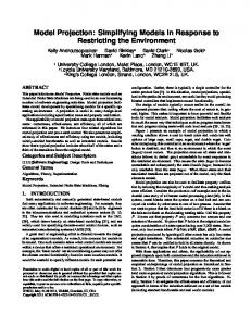
Figure 6 depicts the architecture of most IPSEC gateways.
IPS E C tu nnel
H ost Security gat ew ay
Figure 7 VPN scenario Preshared keys
Preshared keys
VPN establishment
Certification Authority
The process of establishing a VPN usually involves several steps:
Certificates (RSA, key pair, PKCS 10)
IPSec master keys IPSec SA negociation
IKE
IKE
IPSec flows
IPSec
IPSec IPSec session keys
Figure 6 Architecture of IPSEC gateways In order to fully understand the scenario it is useful to know the different levels in this architecture: Authentication of the members is achieved using certificates or pre-shared keys. In the case of certificate usage a Certification Authority (CA) is required. Given the authorized end-points Internet Key Exchange (IKE) [RFC2409] is used to generate and negotiate security associations (SA) and accompanying session keys. The traffic is secured using IPSEC and the IKE generated keys. IPSEC can provide both authenticated header (AH) [RFC2402], and Encapsulated Security Payload (ESP) [RFC2406] services. Figure 7 shows a typical platform for a VPN scenario:
1. Configuration of the future members of the VPN so that they can authenticate themselves. This usually means installing certificates in the machines, or installing pre-shared keys. This step needs to be done only once, for instance when subscribing for the first time to the service. In RADIOACTIVE, with UCL managed VPN services, the certificates are provided by a UCL CA, when installing the service the first time. In this type of service, we can consider that this step was done once off-line and that it does not interfere with the dynamic establishment or deletion of an IPSEC tunnel. This step is just a pre-requisite. 2. The management station prepares the configurations for each entity of the VPN. 3. The management station connects to each security gateway using a SSH connection. It executes the commands on the security gateways and exits. At this level, the security gateways are ready to establish the VPN, but the IPSEC tunnels are not really up yet. After a while (or immediately), a host sends a packet to its security gateway. If the packet matches the rules, installed in the security gateway for this VPN, then the security gateway will then initiate an IKE negotiation with the end-point of the IPSEC tunnel corresponding to the destination of the packet. The IKE negotiation is a complex procedure that involves some communications between the two gateways. According to what options were selected, the duration of the process can be short or long (1 second is the order of magnitude).
The IPv4 versions of the VPN routers could be done with FreeBSD and Cisco routers. The 6WIND [6wind01] and CAIRN [cairn01] versions are the only ones that support IPSEC in its IPv6 mode, and are being used at present. The last step is repeated for each IPSEC tunnel when the first packets reach the gateways.
VPN termination The VPN termination process is simpler: 1.
The management station prepares the configurations for each entity of the VPN. Usually, this consists of command files.
2.
The management station connects to each security gateway using a SSH connection.
3.
It executes the commands on the security gateways and exits. At this level, the security gateways delete the existing IPsec tunnels.
4.3
The X-Bone
The X-Bone [Touc01] follows much the same general theme as Section 4.3.l. The X-Bone is a system developed at USC/ISI for managing and deploying IPv4 overlays. Its goal is to reduce configuration effort and increase network component sharing. The X-Bone extends current overlay management by introducing dynamic resource discovery, monitoring and component reuse since the nodes (hosts or routers) can simultaneously participate in multiple overlays. It does not require OS specific or application specific modifications, only basic IP in IP encapsulation and existing implementations of dynamic routing and the Domain Name Service (DNS). Its key features include the support of recursive overlays (overlays built on top of other overlays) and the integration of IPsec and dynamic routing. The X-Bone allows users to deploy overlays within seconds without human network manager participation. It manages inter-overlay resource contention by providing a uniform coordination point for overlays. This provides a framework for coordinating reservations, even between different mechanisms that manage a single class of resource. By making overlay establishment a fast, common function, the X-Bone enables new uses for overlays, such as for distributed applications without cumbersome application-level service location and routing support. The X-Bone is a distributed system composed of Resource Daemons (RDs) and Overlay Managers (OMs). Users create overlays by sending a request to an OM using a Web-based GUI or sending a message directly to the
OM API. The OM then uses multicast expanding ring search to discover available RDs and subsequently TCP (with SSL) to configure and monitor resources. The RDs are daemon processes which configure and monitor the resources on the nodes. They listen for invitations on a well-known IP multicast address (using S/MIME authenticated UDP) and respond according to their capabilities and available resources indicating willingness to participate in the overlay. The OM selects an arbitrary subset from those RDs that responded and uses X.509 encrypted TCP/SSL connections to each chosen RD in order to transmit configuration information. The OM is responsible for determining the tunnel endpoint addresses and the routing table entries to be sent to each RD. The basic X-Bone mechanism is tunneling (or IP in IP encapsulation); tunnels allow incremental deployment when the routers in the underlying (base) network are lacking specific protocol capabilities. The X-Bone uses a two-layer tunneling mechanism for each level of the overlay. This results in three IP headers in the case of an overlay on top of the base network. The additional layer permits the use of multicast, dynamic routing and IPsec inside the overlay since these are intrinsically network layer mechanisms. The innermost header (internal) indicates the endpoints in the overlay and the next (external) header acts as a link layer for the overlay indicating the endpoints of the tunnel over which the packet is traversing, the final header (base) indicates the tunnel endpoints in the base network. Currently the X-Bone operates using separate, private IPv4 address spaces for the internal and external addresses of an overlay. Overlay addresses can be re-used among overlays that do not overlap. This is determined by the OM during the initial negotiation phase. The problem of scarce IP addresses has been solved with the introduction of the new Internet Protocol; IP version 6. IPv6 provides bigger address space, seamless support for mobility and mandatory security features. With Virtual Private Networks and/or overlay networks that are tightly controlled and centrally managed, like the X-Bone, address scarcity is generally not an issue. However there other reasons why an IPv6 overlay may be preferable compared to an IPv4 one. The difference is in the unique features of IPv6, better support for mobile nodes, mandatory security features, autoconfiguration and better support for QoS. For instance with regards to QoS, in the current IPv4 networks it may be difficult for a router to determine the QoS Class of a packet, based on information found in the network layer packet header, especially when multiple classes of QoS
are involved and encryption is used. However this is not the case with IPv6-based VPNs, which have the advantage that the class of service can be specified outside the VPN envelope of the IP packets. IPv6 addresses are 128 bits long and in order to be more manageable they are split into two parts; the network part, which involves the highest order bits of the address (netbits) identifying the network that the interface is on, and the host part involving the lowest order bits (hostbits) which are left for identifying the interface to the network or subnetwork (hostbits = 128 – netbits). Providers usually assign /48 networks with 16 bits used for subneting while the remaining 64 bits for the host part which is recommended (but not mandated) to be built from the so called EUI64 addresses (derived from the 48 bit MAC addresses filled in with the bits 0xFFFE in the middle).
particularly that the OM uses IPv4 multicast in order to communicate with the RDs. Moreover X-Bone is written in Perl and at the time of this writing there were no TCP/SSL libraries that operate over IPv6. However the capability of deploying IPv6 overlays is particularly important when the X-Bone components are potentially isolated by IPv4 clouds (see Figure 8). In order to achieve this the creator of an X-Bone overlay should first indicate to the OM the IP version number required for that particular overlay; (IPv4 or IPv6). Also the RDs should respond to the invitations by the OM for participation in an IPv6 overlay only if their network stack supports IPv6. The response is then sent back to the OM using UDP/IPv4.
For the RADIOACTIVE purposes, it was necessary to provide the modifications to the X-Bone in order to run using IPv6. This is an ongoing effort at the time of writing and here we only provide an outline of the method we intend to use, for more details and initial experimental demonstration the reader is referred to [gev:02].
4.4
Extending the X-Bone for IPv6 Overlay Deployment
With X-Bone each level of tunneling (IP encapsulation) is specified in a separate “XboneNodeCommand” command sent from the OM to the RD. Usually there are more than one “tunnel” commands in each message and there are special keywords which control the order of execution. The X-Bone has a simple IPv4 address allocation process; it assigns subnets to the links using a 30 bit netmask (0xfffffffc), or it may assign contiguous addresses in order to maximize the number of hosts. It uses the Net::Netmask Perl Module with two CIDR address blocks 172.26.0.0/16 (external) and 172.27.0.0/16 (internal) and 8 subnet bits allowing for 2^8 subnets (or overlays) and (2^8)/4 hosts (since we want to assign a two bit host ID to each link without using the special bit patterns 00 and 11). At this stage our goal is to extend X-Bone in order to facilitate the deployment of IPv6 overlays on top of existing IPv4 networks. The nodes participating in the IPv6 overlay must themselves have IPv6 support built into their network stacks. IPv6 is not yet ubiquitous (although this is changing fast) and thus we made the minimum set of assumptions about the connectivity both between the participating RDs and between the RDs and the OM. Thus we have assumed that all X-Bone nodes are reachable using IPv4 and
Figure 8 IPv6/IPv4 XBone After this initial negotiation and discovery phase the procedure followed by the OM is almost identical to that followed by the creation of IPv4 overlays, allowing for substantial code reuse and avoiding the duplication of the address allocation procedure in the IPv6 case. We achieve this by treating the IPv4 addresses provided by the allocator (OM) as 32-bit blocks. We subsequently use these blocks in the construction of IPv6 addresses by combining pre-pending a common IPv6 prefix to the IPv4 allocated block. Thus the X-Bone logic required for the creation of overlay networks becomes orthogonal to the IP version number. The price paid for the simplicity is the requirement for all the RDs (those on the IPv6 capable nodes) to share a common, pre-configured IPv6 prefix to be used for the creation of overlays. The length of the prefix has to be less than 96 bits, given that IPv4 addresses are 32 bits long. Alternatively the OM could provide them with the IPv6 prefix in order to ensure that all the RDs use the same prefix. However at this stage we chose the solution of the RDs being pre-configured with a common IPv6
prefix this has the advantage that it does not require changes in the format of the protocol messages between the OM and the RDs. But this is a small price to pay compared to the flexibility, the simplicity and the independence of the XBone protocol logic from the IP version number of the overlay. Instead of requiring an additional IPv6 address allocation procedure or different types of messages we use the IPv4 addresses and the pre-configured IPv6 prefix shared by the RDs (running on the v6 capable nodes) in order to construct appropriate IPv6 addresses for use in the IPv6 overlay. The OM could then use the same v4-tov6 translation procedure for the DNS updates. Thus the Xbone protocol communicates tunnel endpoint numbering that can be extended in the IPv6 case. The X-Bone can be used to bootstrap and manage an Active Networks (AN) infrastructure, deploying them on their own overlays. X-Bone also provides a platform to demonstrate the benefits of AN; although the X-Bone can be deployed prior to the availability of AN support, it can be implemented itself in AN technology.
4.5
Changes due to the ALAN Conferencing and VPNs
The TAG was updated to allow its control communication to be "routed" between either the TAG client and the TAG server (for setting up a client-server reflection), or the VPN Manager (for joining a VPN conference). These two modes of operation now use identical control messages which are defined as XML events. Policies define which events are to be sent where. The TAG client uses pre-defined policies so that TAG events are correctly routed to either the TAG server or VPN manager. Since the VPN manager can be part of a VPN, it can thus enjoy secure communication of encryption keys to the remote reflectors. In summary the following changes were made to the TAG for ALAN purposes: •
XML events define TAG control messages.
•
XML policies define server location.
In addition the design of TAG was changed to integrate the functionality of the VPN proxylet. The Reflector Proxylet was extended to accept (via RMI) new destinations so that it can forward (reflect) to multiple destinations. This is useful for two reasons: 1. In the VPN mode it will allow each reflector to forward traffic to each site. 2. In reflector mode the Reflection Manager proxylet will use the reflector to forward traffic to multiple clients.
Reflection is automatically controlled based on local activity of each multicast stream. The user interface has been re-designed to combine the functions of each mode. Further work on TAG will include the development of the Reflector Proxylet to do media transcoding and policies that define actions to take, based on the bandwidth available. These policies will be stored and retrieved from a directory service.
4.6
VPN, the X-Bone and the ALAN infrastructure
Late in 2000, there was a first demonstration of the integrated system for a DARPA PI meeting. At that time, we were still operating at IPv4 without policies integrated in the ALAN infrastructure. As a result of this work, we became aware of what changes were needed for a complete integration and full development. In the intervening year, these changes have largely been done. For the X-Bone these involved mainly the provision of IPv6 support and greater stability. For the ALAN infrastructure, it required the porting to IPv6, the upgrading of the TAG as described earlier, and the working through of policies. These separate components are now largely ready, so that the next set of integration will start soon.
5
VPN Management Policies
This section describes the management of a dynamic VPN service. Management is realized as various scenarios that relate to the establishment or tear-down of a VPN, or parts thereof. A VPN Manager centralizes the access control, and can be used as a final arbiter as to which endpoints or sites are allowed to join or leave a specific VPN. A user of an active service sends events to the VPN Manager to join or leave a VPN. An optional extension to this model is an ability to query the parameters associated with an existing VPN. The VPN Manager sends back an event to the user or active service to indicate whether the requested operation was accepted or not. The VPN also sends events to the routers to configure the VPN. The management policies are defined on the basis of the events. Create/Join VPN Event: For this event, users (or active services) send a Join-Keep_Alive XML-based message to create a new, or join an existing, VPN. This message provides all the information needed to describe the specific VPN that the user or active service wants to create (or join). This information itself can be a preregistered VPN identification number or a description of the type of information/traffic to be carried throughout the
lifetime of the VPN. The Create/Join message also describes the authentication information needed to validate the user or active service doing the requests. Several scenarios where this message is involved are presented below. No pre-existing VPN & no other requests to join the VPN. In this case, the VPN manager receives a request event, but takes no further action because there are no other participant(s). No pre-existing VPN & one pre-existing request to join the VPN. This case represents a second participant of the VPN, and now the VPN manager can establish a VPN between the appropriate routers. Existing VPN. The VPN manager adds a new participant in the VPN. This requires updates to all the existing routers participating in the VPN. In each of the above scenarios, a confirmation message is sent so that a level of assurance exists that the message has been received and acted upon by the VPN manager. Subsequent Join/Create messages by the participants act as a means of refreshing the soft state associated with a VPN participant. Leave VPN Event: For this event, the VPN manager removes a router from the VPN, and updates all the other routers with this updated information. If no VPN exists, the message is discarded. Query VPN Event: This is considered an optional event that produces additional information for a VPN participant. For example, participants may require knowing the identities of other participants in the VPN in case they have access policy restrictions. There are two types of policies that can be applied to the dynamic management of a VPN. The first is centralized, at the VPN manager. Policies based on access control can be used by the VPN manager to reflect a final point of authority about who is allowed to join the VPN. Other centralized policies may exist reflecting the form of security used to validate credentials for those requesting to join or leave a VPN. Policies for VPN management may also be in the form of a decentralized system, reflecting the management decisions of individual users participating in a VPN. In this case, there may exist access control policies determining whether a given end-point is allowed to join a specific VPN, or if certain types of traffic may enter or exit the local endpoint of a VPN. The system is described as it would be for the more conventional VPNs used in ANDROID. The situation for use with the X-Bone used in RADIOACTIVE differs in two respects. First there is no incremental addition or tear down of links; at that point a complete new topology must
be established. Secondly, for the X-Bone not only the routers but all the participating nodes have to be specified.
6
Security Considerations
There has been a wide-ranging look at the security needs of this total system [prnj01]. At the platform security level, the proxylet deployer is authenticated using digital signatures. The same applies to policies, notifications, and proxylet metadata. At the user security level, certificates and digital signatures are used to authenticate actors (end users, operators, and proxylets acting on their behalf). At the management security level, management interfaces and the directory itself also need to be secured, and access to its data and functions authorized properly. This uses the same mechanisms as those at the platform level.
6.1
Authentication of actors
Authentication of actors at the boundary of the system can be achieved by various mechanisms, from a standard login password to the use of a smart card. We propose to use Java Authentication and Authorization Services (JAAS) [sun01b], for this purpose. JAAS is included in the V1.4 Java SDK [sun01a] and is based on Pluggable Authentication Modules (PAM), which makes authentication configurable without impacting on the application level, and includes the necessary management tools, and will support smart cards. JAAS also extends the existing, code-based Java security architecture by adding principal-based mechanisms for access control based on users, groups and roles to the Java policy file. Management of the policy files may be done or supported by the SDK’s policytool. The issue of authentication to others, and of delegation of authority (e.g., by an operator to a proxylet) is not addressed by JAAS. This might be covered by a Java implementation of the IETF’s GSS-API (cf. RFC 2853), which does support these functions.
6.2
Proxylet Security
The policies on the active server form a security envelope within which the proxylet can securely execute. The security policies are interpreted, and the security envelope is formed, by the security manager. No proxylet can be allowed to run unless the security manager sends the load event to the EEP. The security manager performs a number of security actions: •
Proxylet deployer authentication is performed using role matching (digital signature).
•
The authentication of proxylets is performed using the JAR signing (with the private key of the creator).
•
Proxylet access control is achieved through alteration of the java.policy file which controls access to resources.
6.3
Management
In the ANDROID project, great care is taken to secure all parts of the management information – including when it is stored and when it is in transit. This aspect is not included in the RADIOACTIVE project.
6.4
The Transcoding Active Gateway (TAG)
The TAG is the instrument used to provide inter-site connectivity of group communications over unicast links. Within the context of RADIOACTIVE, it has four primary roles: •
Requesting to join or leave a VPN.
•
Requesting to join or leave a reflection group.
•
Reflection of multicast traffic through a VPN.
•
Filtering of traffic by selective blocking.
The first two roles are activated by the presence, or subsequent lack of users participating in a group identified as subject to active service1. If a site is not part of a VPN, then when a user either joins, or sends data to, an active group, the TAG proxylet attempts to do the following: Check to determine if a policy exists that allows or disallows the site to participate in that group. This type of policy represents a distributed access control of group communication. If it is not allowed, then no other action is taken. Otherwise, the following is attempted:
6.5
Secure Conferencing
The secure conferencing has been described in [kirst99] and [kirst00]. The media streams are encrypted at the application level. The details of the conference, including the encryption keys, are kept in a secured conference store (SCS) running on an Apache web server. Users are registered with the store using their certificates. There are extensive facilities for conference organizers to set up access control lists constraining access to the conference store to those desired by the organizer. At present we have seen no reason to have this aspect of the system requiring policy control. Mechanisms requiring users to access a centralized store have problems in scalability and reliability. We may in the future make the whole SCS into a Proxylet; this would allow additional proxies to be set up on demand. Such a development would require policy control.
7
The Final Demonstration
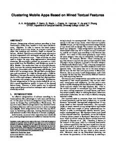
The final demonstration will build up the configuration of Fig. 9 – with the whole system running IPv6, and starting with Active Servers with no VPN. Each workstation in turn will try to join a multimedia conference. As each user tries to join, the active server at each site will discover/determine the presence of group members. If there is no TAG running, the Policy will be to load a TAG onto the Active Server, from the AA store, and the policy from the policy store. It will also send the configuration information to the X-Bone manager, which will set up a new VPN overlay. The communication at each site is multicast; the communication over the VPN is unicast to all addressees over the VPN. This process is repeated as each new user comes in. As any user leaves, a new configuration is set up again without that user.
An XML event is sent to the VPN manager to request that its site be added to a VPN. A policy may exist at the VPN manager that denies or accepts requests from individual sites. This type of policy represents a centralized control of group communication. An XML event is sent to the Reflector manager to register its presence. Note: the Reflection and the VPN manager can be co-resident or in different hosts. At this time, we do not plan on having policies defined for the Reflection manager - but this may change. When all users at a site stop sending data, or leave the group, and the site is a member of the VPN, then the TAG proxylet sends a leave request to the VPN manager and updates the reflector manager in the change of status. 1
For the sake of simplicity, we term these groups as “active” groups or flows.
UCL-CS
-Xbone Node
Internet 2
- AS + TAG - Host + NTE/VIC ISI
Site-A
Figure 9 Schematic of the Final Demonstration
8
Conclusions
This paper has described the architecture for active networking developed within the ANDROID and RADIOACTIVE projects. In particular, it has focused on management-related issues, such as policies, which emerge in a large-scale open programmable environment. It has carried through the whole system for multimedia conferencing over X-Bone overlay networks. Conventional network management techniques will not be able to manage at the level of individual processes, particularly when they are only active within a single instance of a distributed application. We have provided extensive references on different aspects of the system. Space considerations do not allow us to give details of many of the vital areas like the policies used, the management system, the active services or the security system. The system is, however, very flexible; the snapshot shown here is just a taste of what can be done with the system. It is intended to deploy the system in two IPv6-based projects, 6winit [kirst02] and 6NET [6net02] where the main focus is IPv6 deployment – but including wireless access.
9
Acknowledgements
We acknowledge gratefully the support from DARPA for the work on the RADIOACTIVE project (MDA-99799-1-009), and from the European commission on the ANDROID project (IST-1999-10299).
10
References
[6wind01] 6WIND http://www.6wind.com [6net02] 6NET Project http://www.sixnet.org [alex97] Alexander, DS et al, “Active Network Encapsulation Protocol (ANEP)”. http://www.cis.upenn.edu/switchware/ANEP/docs/A NEP.txt, 1997 [amir98] Amir, E et al., “An active service framework and its application to real time multimedia transcoding” Computer Communications review 28, 4, pp178-189, Oct 1998 [apac01] http://www.apache.org/ [brad01] Braden, R et al., “A-BONE: Active Network Backbone. http://www.csl.sri.com/ancors/A-Bone
[carl01] The ANDROID project; http://www.cs.ucl.ac.uk/research/android [damn00] Damianou N., Dulay N., Lupu E., Sloman M., “Ponder: A Language for Specifying Security and Management Policies for Distributed Systems”, Imperial College Research Report DoC 2001, Jan. 2000. [darpa] DARPA Active Network Program, http://www.darpa.mil/ito/research/ anets/projects.html [fish01] Fisher et al. ANDROID deliverable: D5: Active Networking Architecture http://www.cs.ucl.ac.uk/research/android/D5_release. pdf [fry99]. Fry, M and A. Ghosh, “Application Layer Active Networking” Computer Networks, 31, 7, pp. 655-667, 1999 [gev01] P.Gevros, “Deploying IPv6 Overlays with the Xbone” http://www.cs.ucl.ac.uk/staff/p.gevros/xbv4v6-demo/ [ghos00] Ghosh, A., M. Fry and J. Crowcroft, “An Architecture for Application Layer Routing''; Yasuda, H. (Ed), Active Networks, LNCS 1942, Springer pp. 71--86. ISBN 3-540-41179-8 Springer-Verlag, Oct. 2000 [has00] Hasler, K, “The UCL Transcoding Active Gateway” http://wwwmice.cs.ucl.ac.uk/multimedia/software/tag/ [kirst99] Kirstein, PT, et al, "Secure Multimedia Conferencing, A Secure Multicast Conferencing Architecture", Proc. 4th Int. Distributed Conf., Madrid, 1999. [kirst00] Kirstein, PT, et al, "A Secure Multicast Conferencing", DISCEX 2000, pp 54-63, IEEE Computer Society, 2000. [kirst01] RADIOACTIVE project; http://www.cs.ucl.ac.uk/research/radioactive [kirst02] 6WINIT project http://www.6winit.org [lam98] L. Lambrinos, P. Kirstein, and V. Hardman, “The Multicast Multimedia Conference Recorder”, Proceedings of the 7th International Conference on Computer Communications and Networks, October 1998.
[cairn01] http://cairn.isi.edu/cairn.jhtml
[mecc02] Hasler, K. et al. http://wwwmice.cs.ucl.ac.uk/multimedia/software/index
[calv99] Calvert. K, “Architectural framework for Active Network”, http://www.darpa.mil/ito/research/anets/Arcdocs.html
[mars99] Marshall, IW et al, "Application-level Programmable Network Environment", BT Technology Journal, Vol. 17, No. 2, April 1999.
[mars00a] W Marshall and M Banfield, “An architecture for application layer active networking”, IEE Workshop on Application Level Active Networks: Techniques and Deployment”, November 2000. [mars00b]. Marshall, IW et. al., "Active management of multi-service networks", Proc. IEEE NOMS2000 pp981-3 [mars01] Marshall, IW et al. “A Novel Architecture For Active Service Management”, IFIP/IEEE International Symposium on Integrated Network Management (IM 2001), Seattle, 2001 [midd01] “Middlebox Communication Architecture and framework”, Internet Draft, Work in progress (draftietf-midcom-framework-06.txt) December 2001 [nata01] Natarajan R et al.., “A XML based Policy-Driven Information Service” IEEE/IFIP International Symposium on Integrated Network Management (IM’2001), Seattle, May 2001. [peter99] Peterson. L, “NodeOS Interface Specification”. Technical Report, Active networks NodeOS Working Group, 1999. http://www.cs.princeton.edu/nsg/papers/nodeos.ps [prjn01] Prnjat. O, L. Sacks, "Policy-Based Resource Management for Application Level Active Networks", Second IEEE Latin American Network Operations and Management Symposium LANOMS 2001; Belo Horizonte, Brazil, August 2001. [RFC2402] S. Kent, R. Atkinson, "IP Authentication Header", RFC 2402. [RFC2406] S. Kent, R. Atkinson, "IP Encapsulating Security Payload (ESP)", RFC 2406. [RFC2409] D. Harkins, D. Carrel, "The Internet Key Exchange (IKE)", RFC 2409. [sun01a] JDK 1.4 : http://java.sun.com/j2se/1.4 [sun01b] JAAS http://java.sun.com/products/jaas [touc01] Touch. J. et al, “Dynamic Internet Overlay Deployment and Management Using the X-Bone”, Computer Networks, July 2001, pp. 117-135. [tenn97] D. Tennenhouse, J. M. Smith, W. D. Sincoskie, D. J. Wetherall and G. J. Minden, “A Survey of Active Network Research”, IEEE Communications Magazine, vol. 35, no. 1, 1997 [XML01a] XML Schema Part 0: Primer W3C Recommendation, 2 May 2001 http://www.w3.org/TR/xmlschema-0, [XML01b] XML Schema Part 2: Datatypes W3C Recommendation 2 May 2001 http://www.w3.org/TR/xmlschema-2
[XLST01] http://www.w3.org/TR/xslt
11
Appendix A
An example policy from a machine at UCL, supplying notification rule to trigger on the event below: 10.113.58.33MIDServera ndroidmid.10.113.58.3310.11 3.58.33notificationtablepolicytrue configureMIDco nfigureNotificationTable ca347bc0-df78-11d5-789b-00018347ec1b 128.16.64.18080falseadd< /actions> An example VPN-Join event from a machine at UCL, attempting to join “VPN Example session”, supplying login and password for access to VPN manager: ca347bc0-df78-11d5-789b00018347ec1b 128.16.64.1 TAG 3 VPN-Join-Request login password TAG: VPN Example Session, UK 3