Vol. 128 (2015)
ACTA PHYSICA POLONICA A
No. 2-B
Special issue of the International Conference on Computational and Experimental Science and Engineering (ICCESEN 2014)
Real Time Visual Servoing of a 6-DOF Robotic Arm using Fuzzy-PID Controller N.G. Adar∗ , A. Egrisogut Tiryaki and R. Kozan Sakarya University, Mechanical Engineering Department, Sakarya, Turkey Vision based robot applications have taken a great deal of attention, with the development of electronic and computer technology. The visual feedback loop is very effective for improving the dexterity and flexibility. In this study, application of real time visual servoing approach is presented that enables a robot to robustly execute arm grasping and manipulation tasks. This task is decomposed on four stages a) finding object b) determining object’s pose c) moving the robotic arm from an initial position towards the object d) grasping the object. The robot used in this work consists of an arm and head parts. The robotic arm has six degree of freedom, five degree of freedom are located at the arm while one degree of freedom is assigned to the gripper. Head has two degree of fredom which is pan-tilt platform. The image-based control strategy is designed using Fuzzy-PID controller. In this way, position error between target object and griper is minimized and the gripper can grasp the target object precisely. Real-time implementation of the proposed method is carried out using Matlab-Simulink. Experimental results show that, the developed design is valid to detect and grasp objects in real time. DOI: 10.12693/APhysPolA.128.B-348 PACS: 45.40.Ln, 42.30.Tz
1. Introduction Vision is considered an effective robotic sensor allowing for noncontact measurements providing useful information about the environment. For this propose, cameras is used many robotic applications. Visual-feedback control, where the combination of computer vision and feedback control is utilized, can increase the overall accuracy of autonomous robotic systems. This control method is referred to as visual servoing [1]. Various visual servoing techniques, have been developed and introduced for experimenting and testing [2, 3], such as image based visual servoing (IBVS) [5], position based visual servoing (PBVS) [5] and 2.5 D visual servoing [6]. In this study, PBVS was used to implement the system. In PBVS systems (e.g., [7, 8]) image features are extracted from a 2D image and used to estimate the pose of a target, with respect to the camera, within a Cartesian reference frame. Although many theoretical studies in the literature encounter, practical work is seen in recent years. SanchezLopeza et al. [9] propose a methodology to segment coloured objects using stereovision system in order to recover 3D pose to feedback a controller. Their methodology runs in real time and is suitable to perform continuous visual servoing. Monjaraz et al. [10] have presented a new methodology to design PBVS for planar robots in fixed camera configuration. The class of controllers are energy-shaping based, and they are described by control laws composed of the gradient of an articial potential energy plus a linear velocity feedback. Moughlbay et al. [11] present a work of integration of real-time visual servoing
∗ corresponding
author; e-mail:
[email protected]
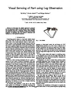
techniques in performing self-localization and different manipulation tasks on a NAO humanoid robot in closed loop. Kar and Behera [12] propose a fuzzy SOM network based visual motor control. The proposed scheme has been implemented in real time on a 7 dof Power Cube manipulator, and the results are found to corroborate the theoretical findings. Fedrizzi et al. in [5] present a mobile manipulation platform that deal with the problem of planning with uncertainty. They propose method is called action-related place (ARPlace) [13]. In this paper, PBVS algorithm is developed to manipulate and grasp to the different height object in real-time design. The methodology proposed consists of four steps a) finding object b) determining object’s pose c) moving the robotic arm from an initial position towards the object d) grasping the object. By using this method, the robot can be guided successfully to grasp the target object. 2. Upper torso humanoid robot platform Robot is approximately anthropomorphic in configuration and scale. The main hardware components of the experimental setup consist of a computer, upper-torso humanoid robot and usb to RS-485 converter. Figure 1 shows the mechanical configuration of our experimental upper-torso humanoid robot. Robot consist of two arms and head which are mounted on body. Each arm has 6-DOF: three in the shoulder, two at the elbow and one for gripper. The camera system mounted on the pan-tilt robot head. All degrees of freedom are driven by Dynamixel Servo Motor [14]. These servo motors embedded with sensors can feedback position, speed, load, temperature, etc., in real time. Each motor carries a microcontroller with a RS-485 interface. Thus, the RS-485 protocol is used for communication from PC direct to the robot. The robot is programmed using Matlab/Simulink.
(B-348)
Real Time Visual Servoing of a 6-DOF Robotic Arm using Fuzzy-PID Controller
B-349
The Denavit–Hartenberg (DH) convention and methodology are used to derive arm and head kinematics. The coordinate frame assignment and the DH parameters are depicted in Fig. 2 and listed in Table I for arm and head respectively. Object x − y − z coordinate according to the camera was computed using image processing technique to grasp the object. Each joint angle must be calculated to manipulate this x − y − z coordinate. For this purpose, the inverse kinematic equations are extracted using the analytical solution approach. 3. Image processing Camera is a powerful sensor which provides a remarkable amount of information that can be used to control a robot. Image processing is a computational process that transforms one or more input images into an output image [15]. Image processing is the most important part of the visual servoing. Some main part of image processing steps will be discussed in this section. 3.1. Object recognition For a grasping task, the first step is to find the interested object in the current image. Image segmentation is typically used to recognise object in images. Segmentation refers to the operation of partitioning an image into component parts, or into separate objects [16]. Many methods are existed in segmentation. In this study, Thresholding method is selected. Thresholding is a vital part of image segmentation, where we wish to isolate objects from the background. It is also an important component of robot vision [15]. After thresholding process binary image is obtained. This image may contain numerous noise and texture. Morphological image processing pursues the goals of removing these imperfections by accounting for the form and structure of the image. Image processing step is shown in below Fig. 3.
Fig. 1.
Experimental setup.
Fig. 2.
Coordinate frames for robot head and arm. TABLE I
The DH parameters for robot arm and head. di
1 2 3 4 5 1 2 3
αi ai a) robot arm d1 = 70 mm 90◦ 0 0 90◦ 0 d3 = 250 mm 90◦ 0 0 90◦ 0 d5 = 250 mm 90◦ 0 b) head 0 90◦ 0 0 90◦ 0 d7 = 60 mm 0 0
θi θ1 + 90◦ θ2 + 90◦ θ3 + 90◦ θ4 θ5 θ6 + 90◦ θ7 + 90◦ θ8
Fig. 3.
Image processing steps.
3.2. Object pose estimation After having black-white image, meaningful data is obtained for PBSV. Centre and 3D pose coordinate of target object are calculated. Using moment of an image, total mass of the region and the centre of mass or centroid of region can be calculated. All measurements referred in this paper are obtained by using pinhole camera model. Using the pinhole model of the camera, the position of the target can be achieved. The z-coordinate of the object is calculated using the lens law [15].
B-350
N.G. Adar, A. Egrisogut Tiryaki, R. Kozan 4. Fuzzy-PID controller
Self-tuning fuzzy PID controller is auto-adaptive controller that is used to determine Kp , Ki and Kd parameters of PID controller. Mamdani’s fuzzy inference method is used the system with two inputs and one output. The controller uses the error and the rate of change of error as its inputs while Kp , Ki and Kd are outputs respectively. Practically there are three base rules tables for Kp , Ki and Kd . The Kp of the rule table is given in Table II as an example, Ki and Kd are formed similarly. TABLE II Fig. 5. Block servoing.
Rule table for Kp . e/( de/ dt) N Z P
N small medium small
Z medium big medium
diagram
of
position
based
visual
P small medium small
The membership functions of inputs (e, de/ dt) and output (Kp ) fuzzy sets are shown in Fig. 4.
Fig. 6.
Fig. 4. The membership functions b) derivative of error, and c) Kp .
of
a)
error,
5. Position based visual servo design visual servoing is a robot control method which uses the image obtained from the camera in order to determine the feedback signal. In this study, PBVS approach was used to verify the effectiveness of object recognition and 3D coordinate estimation algorithms. The architecture of the proposed position based visual servoing is shown in Fig. 5. Flow chart of the grasping algorithm is given in Fig. 6. 6. Experimental results Developed algorithm was tested using objects with different heights and width 5 cm. The object was located at a random position in front of the robot. Robot manipulated its arm and tried to grasp the object. At this time target and real x − y − z position of gripper were
Flow chart of algorithm.
saved. Figure 7 shows one of the x − y − z position of gripper. Real-reference x − y − z and error values that belong to the object in three different height are given in the Table III. 7. Conclusion This paper presents an application of real time Position Based visual servoing that enables a robot to robustly execute arm grasping and manipulation tasks. The effectiveness of the proposed method has been validated through experiments. The results demonstrate that robot can successfully capture objects of different sizes with developed algorithm. The x − y − z position errors are calculated to be less than 1%. Taking into account the x − y − z position at the end of the robot arm motion are calculated position error. When the robot arm controlled with classic PID, increase in integral coefficient (Ki parameter) is caused overshoot. Additionally, settling time is too long as Ki parameter decreases. Using Fuzzy-PID has overcome this problem. This approach can be extended for non-uniform object to grasp and manipulate task.
Real Time Visual Servoing of a 6-DOF Robotic Arm using Fuzzy-PID Controller
Fig. 7.
B-351
a) x position, b) y position, and c) z position. Solid line: reference, dashed line: real position. TABLE III Error and real-reference x − y − z values. Object height
reference x y 16.51 31.89 50 cm 15.12 30.08 5.62 31.41 7.3270 cm 34.44 1.6 32.02 14.05 29.82 11.9 34.59 90 cm 11.22 33.68 3.42 33.69
z –8.9 –5.9 –7.34 –7.47 –7.71 –5.57 –10.14 –7.76 –4.34
x 16.62 15.21 5.61 7.28 1.61 13.92 11.79 11.3 3.41
Acknowledgments This work was supported by Research Fund of the Sakarya University. Project Number: 2013-01-06-032. References [1] S. Hutchinson, G.D. Hager, P.I. Corke, IEEE T. Robotic. Autom. 12, 651 (1996). [2] F. Chaumette, S. Hutchinson, IEEE Robot. Autom. Mag. 13, 82 (2006). [3] F. Chaumette, S. Hutchinson, IEEE Robot. Autom. Mag. 14, 109 (2007). [4] T. Hamel, R. Mahony, IEEE T. Robotic. Autom. 18, 187 (2002). [5] W.J. Wilson, C.H. Williams, G.S. Bell, IEEE T. Robotic. Autom. 12, 684 (1996). [6] F. Chaumette, E. Malis, in: Proc. of IEEE International Conference on Robotics and Automation (ICRA), 24–28 April, San Francisco, 2000. [7] Y. Shen, Y.H. Liu, N. Xi, in: IEEE/RSJ Int. Conf. on Intelligent Robots and Systems, September, Lausanne 2002.
real y 31.99 30.12 31.68 34.6 32.15 30.03 34.73 34.01 33.88
z –9.13 –5.85 –7.37 –7.50 –7.81 –5.84 –10.20 –8.04 –4.44
x –0.662 –0.592 0.178 0.549 –0.621 0.934 0.933 –0.708 0.293
% error y –0.313 –0.133 –0.852 –0.462 –0.404 –0.699 –0.403 –0.970 –0.561
z 0.565 0.855 –0.407 –0.400 –0.516 –0.713 –0.588 –0.640 –0.686
[8] J. Stavnitzky, D. Capson, IEEE T. Robotic. Autom. 16, 732 (2000). [9] J.R. Sanchez-Lopeza, A. Marin-Hernandeza, E.R. Palacios-Hernandez, H.V. Rios-Figueroa, L.F. Marin-Urias, in: The 2013 Iberoamerican Conference on Electronics Engineering and Computer Science (CIIECC 2013), 2013. [10] J. Cid-Monjaraz, F. Reyes-Cortes, P. SanchezSanchez, in: Industrial Informatics (INDIN 2009), 23–26 June 2009, Cardiff, Wales. [11] A. Moughlbay, E. Cervera, P. Martinet, Intelligent Autonomous Systems 12, 321 (2013). [12] I. Kar, L. Behera, ISR 3, 49 (2010). [13] A. Fedrizzi, L. Mosenlechner, F. Stulp, M. Beetz, in: Advanced Robotics, 2009 (ICAR 2009), 22–26 June 2009, Munich, Germany. [14] http://www.robotis.com/xe/dynamixel_en. [15] P. Corke, Robotics Vision and Control Fundamental Algorithms in Matlab, 1st ed., Springer, 2011. [16] A. McAndrew, Introduction to Digital Image Processing With Matlab, 1st ed., Course Technology, 2004.