during object oriented software development. Since the UML class diagram is a so-called âbridgeâ between software specification at the user side and software ...
Scientific Journal of Riga Technical University Computer Science. Applied Computer Systems
DOI: 10.2478/v10143-011-0023-4
2011
________________________________________________________________________________________________ Volume 44
Role of UML Class Diagram in Object-Oriented Software Development Oksana Nikiforova1, Janis Sejans2, Antons Cernickins3 , 1-3Riga Technical University Abstract – UML is an industrial standard for object-oriented software specification which offers a notation for class modeling during object oriented software development. Since the UML class diagram is a so-called “bridge” between software specification at the user side and software realization at the developer side, it requires strong guidelines for identification of class objects from the problem domain and notational conventions for modeling of the class diagram for its further usage in system coding. This paper presents a discussion on problematic stages and possible element transformations into software components. Several conclusions are drawn on potential usage of the class diagram in industry. Keywords: code generation, MDA transformation, model-tomodel transformation, UML class diagram,
I.INTRODUCTION The increasing role of modeling in software system development promotes a methodology, mostly represented by OMG solution for system abstraction, modeling, development, and reuse—Model Driven Architecture (MDA) [1]. The key component of system modeling, which underlies the principles of MDA—Unified Modeling Language (UML)—is used to define several kinds of diagrams, their elements and notation [2]. In fact, UML diagrams should be considered as a way of describing the system from various perspectives: whereas a static diagram is used to represent the structure of the system, dynamic diagrams describe its behavior. The main goal of MDA is to provide the ability of automated transformations from platform independent models into platform-specific source code. However, due to problems with the definition of system dynamic aspects, as well as their translation into code components, this goal has not yet been achieved [3]. Nevertheless, the description of static elements alone would provide a good starting point for system development and its further refinement with dynamic aspects. This representation defined as a UML class diagram, as well as the study on possible options for generation of software components are the objects of the present research. The class diagram, being the most common in modeling object-oriented systems [2], is used to model the static design view of a system. According to MDA [4], the automatic transition from class diagram into platform-specific software components is done by performing a model transformation, where model elements and parameters are mapped to corresponding elements and parameters in the software code. Since published an article on a renovation of the idea of model application during software development and automatic code generation [5], the industry has still been waiting for
ways to apply these ideas in software projects. This would increase productivity, while maintaining the appropriate level of software quality. Nevertheless, previous forecasts, that MDA will cover the whole area as a tsunami in next ten years (proclaimed at the European Conference of MDA in 2006), the actual impact of MDA on software development has not changed. The authors of this paper propose to investigate the central component of model driven software development, which is the UML class diagram. Two factors are established as limitations of practical usage of the UML class diagram during software development: 1) Software developers do not invest enough effort in a formal definition of class diagram elements from the problem domain, and a class diagram is developed based on hints, human intuition and previous experience working with class diagrams. In fact, some commercial industries find that too much modeling is cumbersome and slows down productivity [6]. “For such projects, it makes sense to use UML as a sketch and have your model contain some architectural diagrams and a few class and sequence diagrams to illustrate key points” [7]; 2) A survey of UML practitioners [8] shows that class diagrams are not fully used for further software development, either for code generation or documentation. The results of this report show differences in several dimensions of UML diagram usage in software development projects including the purposes for which they were used and the roles of clients/users in their creation and approval. Hence class diagram has lost the role it could play in software development – i.e. to serve as a bridge between system specification at the user side and software components at the developer side [9]. The goal of this paper is to investigate the level of class diagram usability in software development and to try to answer the following questions: 1) where is the lack of realization and application of model driven ideas in software development projects; 2) why the software industry does not apply all the ideas of MDA at high level of competence; 3) finally, why the industry is not “covered” with MDA support tools. The paper is structured as follows. Results of the authors’ research on UML class diagram usage in software development projects are discussed in Section 2. To advance practical usage of the class diagram during software development, we need a clear set of elements of the class diagram and solutions for their derivation from the problem
65 Unauthenticated Download Date | 11/20/15 10:41 PM
Scientific Journal of Riga Technical University Computer Science. Applied Computer Systems
DOI: 10.2478/v10143-011-0023-4
2011
________________________________________________________________________________________________ Volume 44 domain. Thus, Section 3 gives a brief review of several Given that the class diagram represents the structure of the techniques and solutions for development of the class diagram system, the notation does not provide behavior of the method, in a more or less formal manner. Software components however by assigning a state chart or activity diagram from a required at the software implementation level and several behavioral diagram group, it is possible to provide information theoretical assumptions of code generation abilities are about a body of the method, which shows system dynamics. described in Section 4. Section 5 demonstrates an example of Similarly, class diagrams can be used for system code generation from a class diagram using the Eclipse documentation. It is not necessary to reflect the whole system platform. In conclusion the authors refer to problems stated in structure, but for example, only an individual part of the the introduction and discuss questions which have been dealt system [10]. One way or another class diagrams represent the static structure of the system. They capture domain units, with and are still open for discussion. resources with which the system operates, but not the II.SEVERAL ISSUES ON UML CLASS DIAGRAM USAGE IN operation of the system dynamics [11]. They are also OBJECT-ORIENTED SOFTWARE DEVELOPMENT abstractions from any particular system implementation Regardless of what software life cycle is used, there are programming language syntax. A UML class diagram serves as a primary artifact during three main activities in software development: analysis (in object oriented software development. During the evolution of conjunction with the requirement definition), design and programming technologies and software development process implementation (with testing). In each of these activities, in general, the current idea of basing software development on UML class diagrams are used differently. models is becoming more and more popular. According to the During the analysis, while collecting information on the idea of Model Driven Architecture [1], the class diagram is a problem domain, the class diagram is viewed from the central component for representation of a solution domain in a conceptual perspective, thus it is called a “conceptual class platform independent manner and serves as a basis for diagram”. The diagram is used as a problem domain generation of platform specific details that are required for dictionary (potential classes) and it contains least specific further generation of a software code. notation. The reason is to facilitate communication with the A class diagram describes the static structure of classes in customer, who is not familiar with the UML notation [10]. the system and relationships between those entities. This way, In the design process class diagrams are supplemented with a class diagram represents the structure of the system, as the technical details, thus more precision and more notation is summarized essence, the base for system operation, but not the used. Classes are populated with attributes and methods, as system dynamics itself. well as different kinds of relations – “structural class The key element in the class diagram is “class”. The other diagrams”, which represent overall system structure elements are different types of relationships between classes, (architecture). Depending on the software development such as aggregation, composition or dependency. To find the process, a UML class diagram may contain a sufficiently usability of class diagram elements, the authors conducted a detailed design – blueprint, while in an iterative process it can study on the UML class diagram usage in industry (in 2007) still be a general system structure – sketch. [12]. The results are summarized in Table 1. Finally, in the implementation process, class diagrams can be used to generate system basic structure (skeleton) code. TABLE I
Specific class
Relationships
Class element
ELEMENT USAGE BASED ON RESPONDENTS’ EXPERIENCE Usable (often) Class stereotype
Irregular use Attribute stereotype
Attribute and method type
Method visibility
Method parameter direction Abstract method
Static method
Used in context
Attribute visibility Default value for attribute and method Multiplicity for attribute and method parameter
Generalization Composition and aggregation
Generalization constraint Inner and outer attribute
Association with defined and undefined navigability Multiplicity
Association name, roles, read direction, constraints
Abstract class
Active class Interface class
Note for additional information
Bi-directional, one-way navigation and nonnavigable association Dependency relationship Realization relationship Association class and N-ary association Template class Provided and required interface Ports XOR constraint User-defined compartment
66 Unauthenticated Download Date | 11/20/15 10:41 PM
Unused (rare) Method stereotype Stereotype icon Package visibility (~) for attribute and method Tagged value Static attribute Derived attribute Constraint on attribute and method Generalization discriminator and set name Composite structure (composite and aggregate attribute) Dependency relationship stereotype Class with qualifier Internal class structure Powertype generalization
Scientific Journal of Riga Technical University Computer Science. Applied Computer Systems
DOI: 10.2478/v10143-011-0023-4
2011
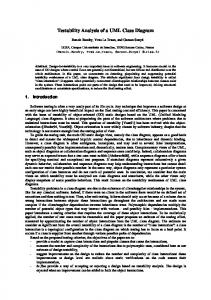
________________________________________________________________________________________________ Volume 44 In order to properly implement the usage of a class diagram, The survey was sent to a number of existing software development companies in Latvia, with an aim to clarify what we need knowledge about: 1. Retrieving the information from the problem domain UML class diagram elements they were typically using in the projects. The survey showed a subsequent failure: not all description and deriving a class diagram for further use. This companies used UML tools which could allow the diagram information should be simultaneously complete and creator to use the wide range of notation included in the consistent, see current research in Chapter 3. 2. How and what software components we can get from a survey. This means that UML tools, as such, limit the usability of UML notation. For example, MS Visio does not provide the class diagram via transformation into code. Based on this required interface, internal class structure (parts, ports). At the knowledge we can define transformation rules as well as have same time, there are UML tools, which can handle all notation the possibility of reengineering, see current research in Chapter 4. used in the survey, like Visual Paradigm for UML. Only having both components defined gives the possibility Main elements of the class diagram marked with most common use, are: generalization, aggregation, composition to build a bridge between user oriented models and developer and association (with defined and undefined navigability). In oriented models of a system. In this way a class diagram helps addition, multiplicity is marked as an important part of all to implement software similar to the initial description of these relationships. Association roles, name, direction of system processes [13]. reading and constraint are used irregularly. In the class III.DEFINING A CLASS DIAGRAM FROM THE element, the usable parts are: type for attribute and method, PROBLEM DOMAIN method parameter direction and class stereotype, which in fact is very important for code generation. The conceptual idea of a class diagram has been in use for a For many elements respondents gave completely opposite long time. Several software development methodologies and assessments, thus the same element was assessed both with 10 techniques used to identify classes in problem area or in initial and 0. This fact suggests difference in the level of detail used models have been proposed since then. In fact, the approach in diagrams, as well as possibly different contexts (e.g. proposed by James Rumbaugh in 1991 for Object Modeling programming in C++, Java or creating object databases) and Technique [14] still is considered one of the best approaches the diagram main purpose. These elements include: template for identification of classes at the system domain level, with class, provided/required interface, visibility for method and real-world operations on the domain objects and state attribute, default value, association class, stereotyped diagrams showing the life stories of domain objects. realization and dependency relationship, bi-directional A. Use-Case Based Class Definition navigation and generalization constraints. Rarely used Ivar Jacobson [15] together with Grady Booch and James elements are: class with internal structure, powertype notation, package visibility, stereotyped attribute and method, despite Rumbaugh offered to use the definition of use-cases as a basis for software development [16]. Several other investigations the fact, that the latter one is important for code generation. Usually developers start modeling a class diagram directly also have been initiated in this direction [17], [18], [19]. A before writing an application code, but still they construct the general schema of definition of a class diagram in the use-case initial architecture defined in terms of the class diagram driven approach is shown in Fig. 1 [20]. The use-case oriented approach is based on an effort to manually by reading the requirement specification. Our conclusion about the usage is that first of all UML class define use-cases and users of the system, as well as to describe diagram mainly is used only on a high abstraction level or as a the usage of the system with detailed scenarios that provide a sketch model, if it is used at all. Some respondents replied “we basis for object interaction and sharing of responsibilities are not using UML at all”. Secondly there are no cases with among domain classes (Fig. 1). A more comprehensive real code generation from the class diagram. We can also analysis of object communication results is found in the conclude this from the pure usage of UML 2.0 element definition of class stereotypes. However, software developers often ignore the “use-case notation invention which is straightforward for code generation, like the template class, stereotyped relationships, driven”, making limited or even no use of either use-case attributes and methods as well as tagged values and diagrams or textual use-case descriptions [8]. In fact, constraints. Of course there are two different views on the organizations use different tools for business process analysis class diagram, i.e. visible and detailed, which are diverse in and, therefore, have complete and consistent models of their organizational structure, responsibilities of the employers, terms of the model information level. The problem presented with two different kinds of models – business processes and the structure of documentation a user oriented model and a developer oriented model, can be workflows—in other words, well-structured initial business solved by generation of the class diagram from the initial knowledge [21]. Therefore, the class diagram may be based on the initial knowledge about business and its complete usage for business knowledge (if it is formal enough). generation of software components.
67 Unauthenticated Download Date | 11/20/15 10:41 PM
Scientific Journal of Riga Technical University Computer Science. Applied Computer Systems
DOI: 10.2478/v10143-011-0023-4
2011
e2
ag
ho et
() d8
:A2
g2 g3 sendMessage3() udateReturn()
System classes in Class diagram
b1 method2(c1, c2) method4() method8() D d1 d2 d3 method5()
method1() method3() E e1 e2 e3 method6() method7()
m
m
es sa ge 2
me
ss
() d8
m et ho
d7
()
ho et m
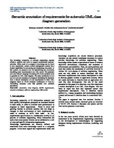
________________________________________________________________________________________________ Volume 44 based on a two-hemisphere model [20], which essence is two step 1 step 2 C B D E UC1 step 3 c1 b1 d1 e1 A1 interrelated models: c2 b2 d2 e2 step 1 step 2 c3 b3 d3 e3 UC2 1) a business process model—describes the processes of the step 3 step 4 step 5 A2 Problem domain classes developed system; Use-case diagram 2) a concept model—describes objects and their interaction Communication diagram (UC1+UC2) Sequence diagram (UC1) during system work. me s :B sag e 1 method2() Two-hemisphere model-driven approach (Fig. 2) [26] :C :B method3() meth :A1 od1() method4() step1 proposes to start the process of software development based :A1 method1() :C step2 :A2 message 3 method2(c1, c2) on the two-hemisphere problem domain model, where one method5() method3() :D model reflects functional (procedural) aspects of the business :E message 1 method6() step3 and the software system, and another model reflects the Sequence diagram (UC2) ... Communication message 1 corresponding concept structures. The co-existence and diagram with class :B :C :D :E :A2 :A1 ... :A1 method1() :F stereotypes method3() ... interrelatedness of the models enables knowledge transfer method4() method5() method2() method4() method6() ... () od 7 message2 from one model to another, as well as the utilization of meth :A2 :C ... :G :H message 3 method7() ... method8() method5() particular knowledge completeness and consistency checks message3 :E method6() [20]. Then elements of the two-hemisphere model are :D transformed into elements of the UML class diagram, using an G intermediate model and analysis of object interaction [13]. F C B g1 f1 f2
sendMessage1() updateReturn() H
:A1
h1 h2 sendMessage2() updateReturn()
Fig. 1. Class diagram development, based on definition of use-cases [20]
So far, another group of software developers prefers to use business process modeling on the initial stages of system analysis [22], [23]. Process-oriented developers may also prefer to use use-cases, however, in this case identification of use-cases is performed in a much more formal way. B. Data-driven System Modeling Although only two main concepts are considered during the analysis of the problem domain—the process and data— several data-oriented approaches can be applied (e.g., such as [24]). Entity-relationship modeling (ERM) is a semiformal data-oriented technique for specifying software systems. It has been widely used for over 30 years for specifying databases [25]. Here, the developers work in correspondence with the definition of data structure since operations with data are of less importance. Of course, operations are needed to access the data, as well as the database itself which should be organized so as to minimize access time. Nevertheless, the operations performed on the data are less significant. Moreover, the manner the software is being developed is not object-oriented, also, the role of the class diagram here is secondary. C. Two-Hemisphere Model-Driven Class Definition In general, the concatenation of data (concept) model with the process diagram can be used to identify classes, their attributes, relationships with other classes and even more—the operations of classes. The idea of common consideration of both models is known; however, this usage in an objectoriented approach was not widely discussed. [26] proposes the way the classes and their object operations can be defined
Fig. 2. Transformations from two-hemisphere model into class diagram in two-hemisphere model driven approach [26]
D. Other Techniques Another attempt to increase the formalization level of the class diagram development is the usage of the so-called formal languages [27]. Formal languages were developed for an unambiguous system specification. Nevertheless formal languages have an important defect – only specialists are able to understand system specifications written in formal languages. Formal languages are based on mathematics. Business specialists usually have difficulties with them. OCL [28], UML profiles [29] and executable UML [30] are some of the modeling solutions that could solve this problem. On the other hand manual transformations that are understandable for the business specialist do not support formal transformation of models at all. [31] describes the results of a survey about different approaches used for transformation of system requirements into system design and implementation. The survey shows the result of analysis on different approaches to transformation of the problem domain description into the UML class diagram during the last 10 years, published in four digital libraries (IEEEXplore, ACM, Science Direct, Springerlink) (see Table II).
68 Unauthenticated Download Date | 11/20/15 10:41 PM
Scientific Journal of Riga Technical University Computer Science. Applied Computer Systems
DOI: 10.2478/v10143-011-0023-4
2011
________________________________________________________________________________________________ Volume 44 TABLE II SURVEY ON APPROACHES TO UML CLASS DIAGRAM CONSTRUCTION Type of approach Type of problem domain description
Amount of papers for exact type of artifact Software 43 / Business 29
Structure of problem domain description Standard model 25 / Non-standard model 25 / Template 1 / Structured natural language 17 / Natural language 10 / Other 3 Type of models of problem domain
Structural 9 / Behavioral 39 / Functional 6 / Other 2
Transformations provided
Yes 58 / No 14
Transformations level
Endogenous (the same language and abstraction level of source and target model) 9 / Exogenous (different) 52
Transformation type
Standard transformation level 7 / non-standard 46
Transformation automation level
Automatic 27 / Interactive (i.e. Semi-automatic) 11 / Manual 22
Tool support
Yes 25 / None 46
Type of validation
Survey 1 / Case Study 32 / Experiment 2 / None 37
Approach scope
Academic 53 / Industry 20
The survey states that there exist enough approaches with different types of solutions for the generation of a UML class diagram. What is more, considering the class diagram construction, we can say that we have quite enough techniques for derivation of elements of the class diagram from the problem domain. The analysis of possibilities to use class diagram elements for further generation of software components is discussed in the next section. IV.ANALYSIS OF SOFTWARE COMPONENT GENERATION The implementation level of abstraction of the software system presented in the form of the class diagram serves as input for the code generation tool. The actual level of abstraction of programming languages has grown from the physical machine level of the first and second generation languages to the abstract machine level of the third and fourth generation languages. [32] states that one objective in using a fourth generation language is a shorter code, and, hence, quicker development and easier maintenance. The use of code generators takes three goals even further, in that the programmers have to provide fewer details to a code generator than they provide to an interpreter or compiler. Therefore it is expected that the use of code generators will increase productivity of the software system development. E. Generation of Class Specification at the Level of Console Application To complete the task of code generation we first need to clarify what component types are developed during system implementation. These types of components give the capability of searching for the corresponding components of a class diagram. In general, a console application of such a system can consist of classes, their definition and realization, relationships among classes, classes visibility etc. All the components required for such an application are already defined by main statements of object-oriented philosophy, the main book we can mention is [33].
So far we can see that different solutions are offered for making the process of the class diagram development more suitable, more formal, or even more “user-friendly”. The main technique here is to look for objects with the same structure (attributes) and behavior (methods) and to group them together into classes. The object is a class instance, which at the defined state performs defined operations. At the moment of object creation, the defined attribute values are assigned to an object, and another object can call it to perform the defined method. Class transformation into the C# programming language is shown in Fig. 3, where the example of the UML class is shown on the left side of Fig. 3 and the correspondent code generated from the class specification is presented on the right side of Fig. 3.
Fig. 3. Example class in both modeling and programming language
The UML class diagram offers different types of associations between classes: these serve as a basis for the generation of several other statements of object-oriented philosophy (e.g., class visibility, generalization, aggregation, usage, dependency, etc.). All the main components of object-oriented paradigms at the console level of system abstraction are being realized since Booch, Rumbaugh and Jacobson made efforts to create code generation tools in the mid 90-ties. The Rational Rose CASE tool was created at that time and has been evolutionarily developed with IBM brand tools as its successor. A lot of open source tools have been developed since that time. However the
69 Unauthenticated Download Date | 11/20/15 10:41 PM
Scientific Journal of Riga Technical University Computer Science. Applied Computer Systems
DOI: 10.2478/v10143-011-0023-4
2011
________________________________________________________________________________________________ Volume 44 By separating the application into layers it is possible to authors based on several experiments with code generation can conclude that despite many papers devoted to the MDA modify each layer independently and do the technological and a lot of theoretical statements about the likelihood of updates for each of them without touching other layers, for model transformation, in fact, the currently available tools out example the application logic. Presentation is the topmost level of the application, which is of the box show very poor results. Since they don’t take into account target programming language syntax and models, that used to show output results from logic level. This is the are not specially adapted, the tool can easily generate program interaction level between user and application, in the clientcode that even does not compile. In other words, current server environment the presentation level appears on the client transformation is a primitive information transfer from model side. Currently there are many frameworks, which support to code, instead of making additional decisions at the model- three layer architecture and where the presentation layer can building and generation process stages, which as a result could be modified based on the target operating system or using at least match syntactically and semantically a proper result style sheets in case of web environment. As mentioned, the output design can be changed without touching the other code. layers. From the MDA and code generation point of view it F. Generation of Software Components for Windows/Forms could be possible to generate a base form for each class or Applications even concatenate related (linked) classes into one form even if The development of business-oriented software systems the relation between classes is one to many, because it is with user-friendly GUI interface is more complicated. In this possible to show many-side classes as a table. There are no case, the generation of a Windows/Forms application from the problems to correctly guess output control for a class attribute, class diagram is considered. In general, Windows/Forms the decision may be based on the attribute type, for example applications rely on three-layer architecture [19]: presentation, Boolean is a check box, String is an edit box, related class is a logic, and data layers (Fig. 4). list box etc. Also from class definition it is possible to correctly address which attributes should be visible and which are used in the background, using attribute get/set flags. If the model is enriched with a sequence or communication diagram which contains an ordered message flow in objects life, it could be possible to use this information in presentation layer by ordering input fields or even opening forms in a provided sequence. Similarly, given that the presentation level fields may be related to each other, affecting each other’s output, this link could be determined from the derived class attributes and the contained fields in the derivation formula. Events which can be called during the form processing, can be labeled with appropriate stereotype which can provide visible separation of other class methods and can be transformed differently from other methods, for example with an additional windows handle parameter. However we still believe that currently some GUI creator tools should be used at the presentation level to modify and adapt the result design, because generation can target and transform the classes thru GUI templates, which should be configured anyway. The logic layer contains application functionality and business rules. All methods and functions are executed in this layer. At this moment class behavior transformation into executable code is the MDA weakest point, because it is not so easy to express algorithms in models. Describing class behavior UML suggests using activity, sequence, communication and state machine diagrams, so the class diagram contains method definition, but the body is expressed in the mentioned diagrams. This means that we have a choice between two options for describing class behavior in the model. We can use the mentioned diagrams to show the object message flow, which will result in so-called “functional Fig. 4 The three-layer architecture block” diagram difficult to read and mixing a low level code with an abstract platform independent model. Or we can use
70 Unauthenticated Download Date | 11/20/15 10:41 PM
Scientific Journal of Riga Technical University Computer Science. Applied Computer Systems
DOI: 10.2478/v10143-011-0023-4
2011
________________________________________________________________________________________________ Volume 44 UML defined OCL [28] and Action languages to formally (i.e., Java) layers. EMF utilizes the concept of the class describe functionality by writing a pseudo-code. There are diagram, at the same time extending it. In general, EMF has also solutions based on UML Profile extensions such as the two models: the first is a meta-model, which describes the UML profile for EJB [3], but the problem still remains: an structure of the model, while the second serves as the actual abstraction level is too low. It does not represent the problem implementation of it (i.e., is the instance of meta-model). EMF uses XMI [36] to persist the model definition. The as a collection of classes, attributes and relationships, instead, the result is composed of entity beans, session beans and Java EMF meta-model definition can be defined based on [37]: classes. Needless to say, such a low level abstraction model XMI document, Java annotations, UML and XML Schema. Once the EMF meta-model is specified, the generation of almost coincides with the source code and transformations of this kind of model are simply straightforward, since there are corresponding Java implementation classes from this model becomes possible. The source code from EMF is generated no changes in the abstraction level. However the authors believe that the fundamental problem with the intention for further modifications. That is why it is the lack of abstract functional components. Thus to describe looks clean and documented right “out of the box” [37]. In fact, with EMF the data model explicitly enhances the class behavior it would be necessary to use pre-defined functional components, so it would be necessary to mix UML visibility and extendibility of the model [37]. It also provides model abstraction with concrete programming languages. As change notification functionality to the model in case of an example the authors remind of the simple square root changes in the model happen. The EMF helps to program function, no one cares about what low-level algorithm interfaces instead of classes. Also, it is possible to regenerate implementation is used to calculate the square root. The the Java source code from the model at any point of time. The EMF Project and EMF Model wizards provide a way programmer just calls sqrt(x) function and gets a result. The same analogy should be used for abstract behavior. The for defining an EMF model from UML [37]. In general, modeler just uses some named component by giving a class Eclipse EMF supports various model formats. However, EMF attribute as a parameter or uses stereotypes and tagged values also provides additional support for IBM/Rational Software and at the same time this component is mapped to a platform Architect (.mdl files). The reason is that RSA was used to specific code. In this way a manageable and transformable “bootstrap” the implementation of EMF itself. Nevertheless, it is possible to create a UML model within Eclipse (via UML2 model is obtained, which describes class behavior. The data layer keeps data neutral and independent from Tools project or any other UML plug-in). The EMF model is based on two meta-models: the Ecore application servers or business logic. It contains the required mapping for storing objects into a data source. To create data and the Genmodel model [35]. While the former contains tables it is already possible to generate SQL scripts from a information about defined classes, the latter contains class diagram, which can be executed to build the required additional information for code generation. The generated source code consists of three packages [35]: database instance. Similarly, it is possible to generate XML 1) Model package contains interfaces and the Factory to files with the correct class structure. For example, the Sparx Enterprise Architect [34] allows generating a DDL model create Java classes; 2) Model implementation package contains the concrete from a PIM model, providing all the necessary transformation rules. Thus this is quite similar to generating a class definition implementation of the interfaces defined in the model (i.e., classes); into a target programming language. 3) Model utility package contains the AdapterFactory. In this way we can assume, theoretically, that all the The central Factory has methods for creating all defined necessary components for software system generation and the basis for such transformations rules can be defined and have to objects. Interfaces and their corresponding implementations be realized by tools. Thus, the impact of the generated code on contain getter and setter (if allowed) methods for each the set of software components, required to be developed, can attribute. Each interface extends the base interface EObject, which together with its corresponding implementation class be valuable and really powerful. EObjectImpl provides a lightweight base class that lets the V.CURRENT FACILITIES OF SOURCE CODE generated interfaces and classes participate in the EMF GENERATION FROM THE UML CLASS DIAGRAM notification and persistence frameworks. In order to run the generated application as a console The Eclipse platform together with Eclipse Modeling application, the main method definition should be considered. Framework (EMF) was selected to examine the most current Furthermore, if visual GUI development for such application facilities of source code generation, as well as to find out how is necessary, then one of the corresponding GUI design plugmodel-driven approaches like MDA perform in real-life ins for Eclipse should be considered. application development. In short, Eclipse is a universal tool While the development process of Eclipse and EMF is platform and an open extensible integrated development fairly convenient and clear, there always is a room for environment (IDE) [35]. In turn, EMF extends The Eclipse improvement. First of all, the current release of EMF is not platform with a solid basis for application development using final, meaning that there is still a lack of stability. In order to modeling and code generation facilities [35]. avoid problems with UML model import, models should From the MDA perspective, EMF should be considered as a contain all primitive types used to define the attributes of framework for platform-independent and platform-specific
71 Unauthenticated Download Date | 11/20/15 10:41 PM
Scientific Journal of Riga Technical University Computer Science. Applied Computer Systems
DOI: 10.2478/v10143-011-0023-4
2011
________________________________________________________________________________________________ Volume 44 model elements (at least, this is true for UML2 Tools Eclipse where one has a lot of approaches for formal construction of plug-in). As soon as an UML model is imported, the them. One of the reasons stated is the assumption that the problem relationships among classes in UML class diagrams should be reassigned manually. This can be achieved by initializing an is not in the construction of a class diagram, but rarely occurs Ecore diagram. In fact, the Ecore diagram can be considered in code generators. The paper summarizes a representative bibliography assembled over the last 20 years in the area of as an EMF representation of a UML class diagram (Fig. 5). object-oriented modeling analysis and approaches to the creation of a UML class diagram. The correspondent scientific literature also includes the MDA/MDD inception as well. The main conclusion is that we have quite enough means to construct a class diagram. At least at the theoretical level we have quite enough transformations ready for solving the task Fig. 5. An example of Ecore diagram of code generation during system implementation, but in Eclipse EMF also lacks the option to define the data layer practice all these means are not sufficiently supported by (like Sparx Systems Enterprise Architect). Currently, the use modern CASE tools at the sufficient level. The aspect of code of additional plug-ins for modeling entity-relationship generation and the results of the analysis of the quality of the diagrams should be considered in order to generate the DDL code generated by modeling tools are discussed in the authors’ of the database schema. However, this means that additional second paper included in this issue [41]. These results clarify time is needed to develop an application, as the ER diagram the question why software developers don’t want to use all the facilities of a UML class diagram. should be defined from scratch. The main reason is that even if a class diagram were Nevertheless, the use of other technologies such as developed in a formal way and contained complete and Hibernate [38] or Teneo [39] would help to eliminate this consistent presentation of the problem domain, still software problem by providing a framework for mapping an objectdevelopers would not be able to fully use it for further oriented domain model to a traditional relational database. The software development due to weaknesses in code generation use of Hibernate and Teneo (which actually is a Hibernate tools, because they don’t support all the required representation in EMF) in itself also is a bit different. transformations into code components to fulfill all the requirements of MDA. More developers and developer VI.CONCLUSION companies should be involved in the development of such Abstraction is the process, where the core principles from a technologies as EMF. The investment will pay off in terms of set of facts or statements are extracted and distilled. In turn, a reduced amount of time spent on other projects. model is an abstraction of something in the real world, Of course, the industrial companies have to meet standards representing a particular set of properties. There are two main of capability and maturity to be able to use all the principles reasons why developers should create a model [24]: and ideas of the most current facilities. However, without 1) for better understanding of a process or an object by investment in something new and revolutionary there would identifying and explaining its key characteristics; be no progress in the current state of the art. 2) for documenting the ideas that developers need to But on the other hand the lack of available powerful tools remember, as well as to make those ideas clear to others. supporting all the aspects discussed in the paper can also be In fact, OMG’s initiative—Model Driven Architecture— regarded as the most determinative and disincentive factor, offers the third reason for using the models in software which hinders valuable MDA/MDD ideas being adopted by development [40]: models are the basis for further code industry. Since the renovation of the idea of model application generation. Moreover, the UML class diagram plays the during software development at the beginning of 21st century central role in promoting this vision in the industry. we still are at the same stage. This can raise doubts about the In this article, the authors investigated the current facilities solvability of the problem. of the source code generation from a UML class diagram, We can discuss an analogy between code generators and analyzing it from various perspectives. These perspectives automatic language translators. Even if we have a condition in include the modeling of a class diagram from initial business both dictionaries, where the word of one language has one and information, as well as concerns about the usage of a class only one interpretation in the other language, we can diagram for generation of software components. encounter a problem similar to one typical for poetry One of the contributions of the paper is a description of the translations. All the words are translated in the correct position state of the art in the area of UML class modeling. This paper and sequence, but the translated text doesn’t rhyme or have analyzes the usage of a class diagram in software meaning. The same analogy can be drawn in programming development. It looks at bigger issues – why MDE is not used language, all the code operators would be at their required in projects, why MDA is not applied in a competent way on places, but the program code as a whole doesn’t “sound” and projects, and why industry does not have good MDA tools. doesn’t operate as it should. The discussion surrounds the question why developers do not spend enough time developing good UML class diagrams,
72 Unauthenticated Download Date | 11/20/15 10:41 PM
Scientific Journal of Riga Technical University Computer Science. Applied Computer Systems
DOI: 10.2478/v10143-011-0023-4
2011
________________________________________________________________________________________________ Volume 44 nd Acknowledgments. The research presented in the paper is [23] J. Jeston and J. Nelis, Business Process Management, 2 Edition, Practical Guidelines to Successful Implementations, Butterworthsupported by the research grant No. FLPP-2009/10 of Riga Heinemann , 2008. Technical University “Development of Conceptual Model for [24] J. Toby, S. S. Teorey, T. N. Lightstone and H. V. Jagadish, “Database Modeling and Design: Logical Design,” 4th Edition, in The Morgan Transition from Traditional Software Development into Kaufmann Series in Data Management Systems, Morgan Kaufmann, MDA-Oriented.” The research presented in the paper partly is 2005. supported by Grant of Latvian Council of Science No. 09.1245 [25] P. Chen, The entity relationship model – towards a unified view of data, ACM Trans. Database Systems, 1, 1976, pp. 9—36. "Methods, models and tools for developing and governance of [26] O. Nikiforova, A. Cernickins and N. Pavlova, “Discussing the agile information systems". REFERENCES [1] [2] [3] [4] [5] [6] [7] [8] [9] [10] [11] [12] [13]
[14] [15] [16] [17] [18] [19] [20]
[21]
[22]
“OMG Model Driven Architecture”, [Online]. Available: http://www.omg.org/mda [Accessed: Sept. 24, 2010]. “OMG Unified Modeling Language”, [Online]. Available: http://www.uml.org [Accessed: Sept. 24, 2010]. O. Pastor and J.C. Molina, Model-Driven Architecture in Practice: A Software Production Enviroment Based on Conceptual Modeling, Springer, 2007, pp. 302. A. Kleppe, J. Warmer and W. Bast, MDA Explained : The Model Driven Architecture – Practise and Promise, Addison Wesley, 2003. J. Siegel, “Developing in OMG’s Model-Driven Architecture,” in OMG document omg/01-12-01 2001. [Online]. Available: http://www.omg.org/mda/papers.htm [Accessed: Sept. 24, 2010]. M. Fowler and K. Scott, UML Distilled: A Brief Guide to the Standard Object Modeling Language, 2nd Ed., Addison-Wesley Prof., 1999. R. Miles and K. Hamilton, Learning UML 2.0, 1st Edition, O'Reilly Media, 2006. B. Dobing and J. Parsons, Dimensions of UML Diagram Use: A Survey of Practitioners, IGI Global, 2008. A. Burton-Jones and P. Meso, “Conceptualizing systems for understanding: An empirical test of decomposition principles in objectoriented analysis,” Information Systems Research, 2006, pp. 101—114. M. Fowler, UML Distilled: a brief guide to the standard object modeling language, 3-rd edition, Addison-Wesley Professional, 2003. – 208 lpp. B. Unhelkar, Verification and Validation for quality of UML 2.0 models, New Jersey: John Wiley-Interscience, 2005, pp. 313. J. Sejans, “Analysis of Notational Elements of UML Class Diagram,” (In Latvian: Valodas UML klašu diagrammas elementu notācijas analīze) Bachelor thesis, Riga Technical University, 2007. O. Nikiforova, “Two Hemisphere Model Driven Approach for Generation of UML Class Diagram in the Context of MDA,” in Huzar, Z., Madeyski, L. (eds.) e-Informatica Software Engineering Journal, vol. 3, issue 1, Wrocław University of Technology, Institute of Applied Informatics, Oficyna Wydawnicza Politechniki Wrocławskiej, Wrocław, Poland, 2009, pp. 59—72. J. Rumbaugh, M. Blaha, W. Premerlani, F. Eddy and W. Lorensen, Object Oriented Modelling and Design, Englewood Cliffs: PrenticeHall, New Jersey, 1991. I. Jacobson, Object Oriented Software Engineering: A Use Case Driven Approach, Addison-Wesley Professional, 1992. I. Jacobson, G. Booch and J. Rumbaugh, The Unified Software Development Process, Addison-Wesley, 2002. C. Larman, Applying UML and Patterns: An Introduction to ObjectOriented Analysis and Design, Prentice Hall, New Jersey, 2000. T. Quatrany, Visual Modeling with Rational Rose 2000 and UML, 2nd Edition, Addison-Wesley, 2000. J. W. Satzinger, R. B. Jackson and S. D. Burd, Object-Oriented Analysis and Design with the Unified Process, Thomson Course Technology, 2005. O. Nikiforova, “Object Interaction as a Central Component of ObjectOriented System Analysis,” International Conference „Evaluation of Novel Approaches to Software Engineering” (ENASE 2010), Proceedings of the 2nd International Workshop „Model Driven Architecture and Modeling Theory Driven Development” (MDA&MTDD 2010), Osis J., Nikiforova O. (Eds.), Greece, Athens, July 2010, SciTePress, Portugal, pp. 3-12. O. Nikiforova and M. Kirikova, “Two-Hemisphere Model Driven Approach: Engineering Based Software Development,” in: 16th International Conference Advanced Information Systems Engineering. Persson A., Stirna J. (Eds.), LNCS 3084, Springer-Verlag Berlin Heidelberg, 2004, pp.219–233. M. Havey, Essential Business Process Modeling, O'Reilly Media, 2005.
[27] [28] [29] [30] [31]
[32] [33] [34] [35] [36] [37] [38] [39] [40] [41]
Difference between Model Driven Architecture and Model Driven Development in the Context of Supporting Tools: Projection of TwoHemisphere Model into Component Model of MDA/MDD” presented at 4th International Conference on Software Engineering Advances. IEEE Computer Society, Conference Proceedings Services, 2009, pp. 1—6. A. B. Webber, Formal Language: A Practical Introduction, Franklin, Beedle & Associates, 2008. “OCL Specification”, [Online]. Available: http://www.omg.org/cgibin/apps/doc?ptc03-10-14.pdf [Accessed: Okt. 7, 2010]. Ambler S.W. Approaches to Agile Model Driven Development (AMDD) Available: http://www.agilemodeling.com/essays/ amddApproaches.htm#Manual S. J. Mellor and M. Balcer, Executable UML: A Foundation for ModelDriven Architecture, Boston, MA: Addison-Wesley, 2002. G. Loniewski, E. Insfran, S. Abrahao, A Systematic Review of the Use of Requirements Techniques in Model-Driven Development, D.C. Petriu, N. Rouguette, O. Haugen (Eds.) the Proceedings of the 13th Conference, MODELS 2010, Model Driven Engineering Languages and Systems, Part II, Oslo, Norway, pp. 213—227 S. R. Schach, Object-Oriented & Classical Software Engineering, 7th Edition, McGraw-hill International Edition, 2007. G. Booch, Object-Oriented Design with Applications, 2nd Edition, Englewood City, California, 1994. “Sparx Enterprise Architect”, [Online]. Available: http://www.sparxsystems.com.au/products/ea/index.html [Accessed: Sept. 19, 2010]. D. Steinberg, F. Budinsky, M. Paternostro and E. Merks, Eclipse Modeling Framework, 2nd Edition, Addison-Wesley, 2008. “Information Technology—XML Metadata Interchange (XMI)”, International Standard, ISO/IEC 19503, First Edition, 2005. “Eclipse Modeling Framework (EMF)—Tutorial”, [Online]. Available: http://www.vogellade/articles/EclipseEMF/article.html [Accessed: Sept. 19, 2010]. “Hibernate—jBoss Community”, [Online]. Available: http://www.hibernate.org [Accessed: Sept. 19, 2010]. “Teneo”, [Online]. Available: http://wiki.eclipse.org/teneo [Accessed: Sept. 19, 2010]. D. Gasevic, D. Djuric and V. Devedzic, Model Driven Engineering and Ontology Development, 2nd Edition, Springer, 2009. J. Sejans, O. Nikiforova, Problems and Perspectives of Code Generation from UML Class Diagram, The Scientific Journal of Riga Technical University, Series Computer Science – Applied Computer Systems, 2011 (accepted for publication)
Oksana Nikiforova received engineering science doctor’s degree (Dr.sc.ing) in information technologies sector (system analysis, modeling and designing, sub-sector) from the Riga Technical University, Latvia, in 2001. She is presently a full professor at the Department of Applied Computer Science of Riga Technical University, where she has worked since 1999. Her current research interests include object-oriented system analysis and modeling, especially related issues in the framework of Model Driven Architecture. In these areas she has published extensively and has been awarded several grants. She has participated and managed several research projects related to the system modeling, analysis and design, as well as participated in several industrial software development projects. She is a member of RTU Academic Assembly, Council of the Faculty of Computer Science and Information Technology, RTU publishing board, RTU Scientific Journal Editorial Board, etc. She is awarded as RTU Young Scientist of the Year 2009.
73 Unauthenticated Download Date | 11/20/15 10:41 PM
Scientific Journaal of Riga Techniccal University Computer Sciennce. Applied Compu uter Systems
DOII: 10.2478/v101443-011-0023-4
2011
____ ____________________________________ _______________________ ____________ _______________________ _______ Volumee 44 Janis Sejan ns obtained engineeering science maaster degree (Mg.sc.ing) in inform mation systems ffrom Riga Techniical University, in 2010. Currentlly he is a PhD student s at the Faculty F of Compputer Science and Information Technology He is a researcher at the Departmentt of Applied Coomputer Science of Riga Technnical University. The T work experieence has been rellated to ERP systeem programming g and implementaation since 2002.. Currently he is running his own company ToownTech and wo orking at Joint S Stock Company Latvian L Roadworks as a program mmer for ERP systtem. w awarded andd included in Rigga Technical Uniiversity Gold Stuudent He was Fund in n 2010. His masteer thesis was awaarded by Verner fon f Siemens as a best research in 2010.
Anton Cernnickins was borrn in 1985, diedd in 2010. Earnned a degree of Bachelor of Engineering Sciences in 2007 7, a degree of Maaster R of Engineeriing Sciences in 2009—both at Riga Technical Unniversity, Latvia. He was a doctooral student at tthe Institute of Applied Compuuter Systems, Rigga Technical Univ versity. He was a reseearcher at the Deepartment of Applied Computer Sccience, RTU. Field of interest: computter science. Speecial interests: moodeling, model-driven developmennt.
Oksana Ņikiforova, Jāānis Sējāns, Antoons Čerņičkins. UML U klašu diaggrammas loma objektorientētā programmatūras p s izstrādē UML ir i industriālais sstandarts objektoorientētā program mmatūras izstrāddē, kas piedāvā dažādu sistēmass aspektu modelē lēšanas notāciju. Viens no sistēm mas modelēēšanas uzdevumiem UML notāciijā ir kalpot parr „tiltu” starp prrogrammatūras sistēmas s specificēšanu lietotāja ppusē un program mmatūras realizāāciju program mmētāja pusē. Šīī uzdevuma risinnāšanai UML vaalodā ir jābūt deefinētām stingrām m prasībām diagrrammu elementuu identificēšanai un sistēmas moddeļa izstrādeei, kur galveno loomu „spēlē” UM ML klašu diagram mmas izstrāde. Kllašu diagramma tiek veidota, apk kopojot informāciiju par izstrādājaamo programmatūūras sistēmu u no lietotāja pusses, un kalpo parr pamatu program mmatūras komponnentu izstrādei. Pašlaik P pastiprinā āta uzmanība ir ppievērsta klašu diiagrammas elemeentu automaatizētai transform mācijai koda fragm mentos. Šis rakstss fokusējas uz klaašu diagrammas lietošanu l program mmatūras izstrādēē no diviem aspektiem, gan aprakkstot dažādu us paņēmienus kllašu diagrammass izstrādes metod dēs no sākotnējaas informācijas par p sistēmu, gan n arī aprakstot ddažas perspektīvaas koda ģenerēšaanas uzdevu umā. Rakstā ir seecināts par to, ka k eksistē pietiek kami daudz pieeeju, lai izstrādātu u UML klašu diiagrammu pilnīgu gu un nepretrunīg gu, un ar formāālām transforrmācijām no dažžādiem problēmvvides apraksta veidiem. Taču kodda ģenerēšanas jo omā joprojām passtāv problēmas, kkā iegūt strādājo ošas programmatūūras kompon nentes. Tas ir iem mesls, kādēļ klašuu diagrammas jop projām tiek lietottas tikai dokumen ntācijai. Pat, ja kllašu diagramma ttiks izstrādāta forrmālā ceļa, tik unn tā, mūsdieenās to vēl nav iespējams lietot koda ģenerēšan nai. Patreizējā kllašu diagrammass versija nesatur pietiekamu info formāciju, kuru varētu v “tiešā” veeidā transforrmēt programmaatūras komponenntos. Koda ģenerrēšanas rīki nepiilda visas modeļvadāmās program mmatūras izstrāddes prasības, līdzz ar to, pieaug rīku r standarrtizācijas nepiecieešamība. Nobeiggumā tiek diskutēēts par esošajām problēmām klaššu diagrammas lietošanā un persppektīvām plašākaai klašu diagramm mas lietošan nai programmatūrras izstrādes projektos. Оксан на Никифороваа, Янис Сеянс,, Антон Черни ичкин. Роль ди иаграммы кла ассов языка UM ML в разработтке объектно-о ориентированн ного програ аммного обеспеечения UML является индусстриальным стандартом для разработки сисстем программ много обеспечен ния, использую ющим объектно о-ориентированн ную логию. Одной изз задач моделиррования системы ы, используя ноотацию UML, является обеспеч чение «моста» м между специфик кацией системы ы на технол сторон не заказчика и рреализацией сисстемы на сторо оне разработчикка. Для решенияя этой задачи в языке UML ддолжны быть оп пределены строогие требоввания к идентиф фикации элементтов диаграмм и разработке моддели системы, где г главную рол ль играет диагррамма классов. Диаграмма Д класссов строиттся, обобщая ин нформацию, поллученную от зак казчика, и долж жна служить осн нованием для реализации систе темы. В последн нее время больш шое вниман ние уделяется реешению проблем мы автоматической генерации ккода из диаграмм мы классов. В статье рассматрииваются два аспеекта использования диаграаммы классов в рразработке прогрраммного обеспечения: с однойй стороны - приеемы конструиров вания диаграммы ы на базе началььной информаци ии о систем ме, а с другой - п перспективы генерации кода из диаграммы д класссов. В статье даается подтверждение того, что заа 20 лет существ вования диаграм ммы классов, разработано достаточно меттодов, приемов и техник для тоого, чтобы считтать, что пробле ема формальногго построения диаграммы д класссов уют проблемы, связанные с автоматическим получением рааботающих ком мпонентов систеемы решенаа. А вот по чаасти генерации кода существу програаммного обеспеччения. И это явлляется одной из причин, почемуу диаграмма клаассов используе ется только для документации, а в полном объеме своих возможностей в процессе разрработки програм ммного обеспечеения не использзуется, даже есл ли разработана формальным об бразом. На данн ный моментт диаграмма клаассов не содерж жит достаточный синтаксис дляя того, чтобы описать все возм можные и необхходимые элемен нты, которые даадут возмож жность генерироовать полноценн ный программны ый код. И CASE E средства, котор рые существуютт в поддержку геенерации кода на н данном этапе, не соответтствуют всем трребованиям для разработки упраавляемой моделя лями системы, тааким образом, во озрастает необхо ходимость стандартизировать таакие CASE средства. В закллючение авторы ы ведут дискусси ию о существую ющих проблемах х в использовани ии диаграммы кллассов языка UM ML и перспекти ивах рения области и использования ди иаграммы классо ов в проектах поо разработке про ограммного обес спечения. расшир
74 Unauthenticated Download Date | 11/20/15 10:41 PM