Globecom 2013 - Cognitive Radio and Networks Symposium
Study on spectrum sharing method based on distance estimation for cognitive radio networks Janne J Lehtomaki Centre for Wireless Communications, University of Oulu P. O. BOX 4500 FIN-90014 University of Oulu, Finland Email:
[email protected]
Kenta Umebayashi Tokyo University of Agriculture and Technology, 2-24-16, Nakacho, Koganei-shi, Tokyo, Japan 184-8588 Email:
[email protected]
Abstract-We investigate a method to set the maximum al
lowable transmit power (MATP) for a secondary base station ( SB) in dynamic spectrum sharing among secondary users ( SUs) and primary users (PUs). In conventional methods, location information is assumed to be available. T hus, the MATP can be set by considering the shadowing between the SB and the PU receivers to satisfy a constraint. Specifically, probability that the interference caused by SB exceeds the allowable interference level should be less than the constrain target probability (CTP). We assume that the location information is not available at secondary network. Instead, the SB uses the received signal strength (RSS) from the PU transmitter for distance estimation. In this case, we have to consider shadowing not only between the SB and the PU receivers, but also between the PU transmitter and the secondary receiver(s). In addition, we also need to account for the uncertainty of the distance. Furthermore, we consider multipath fading. In order to satisfy the CTP, we proposed a two-step approach to setting the MATP where a transmission decision margin and a transmit power margin are utilized. To reduce these margins, we also proposed cooperative MATP setting method utilizing also RSS values from several SUs. Simulation results confirm the efl'ectiveness of the proposed cooperative MATP setting method.
I.
INTRODUCTION
To overcome the spectrum scarcity problem, one promis ing technique is spectrum sharing (SS), with cognitive radio techniques performed by secondary users (SUs) [1]. In the SS approach, SUs can use the spectrum even if the primary user (PU) is active with a constraint on interference at the pu. In some research related to resource allocation with SS, it has been shown that transmit power control can improve the efficiency of spectrum utilization. However, in these studies, perfect instantaneous channel state information (CSI) or chan nel gain in the link from the SU transmitter to the PU receiver was assumed to be available [2]-[5]. However, this approach is not very practical. Instead of the instantaneous CSI, several works assumed that location information (i.e., the distance between the SU transmitter and the PU receiver) is assumed to be available through a database and global positioning system [6]-[8]. Given the location information, the path loss (denoted by L) can be determined and the SU transmitter can set a maximum allowable transmit power (MATP) that gives sufficient PU protection using an appropriate margin as a countermeasure
978-1-4799-1353-4/13/$31.00 ©2013
IEEE
Yasuo Suzuki Tokyo University of Agriculture and Technology, 2-24-16, Nakacho, Koganei-shi, Tokyo, Japan 184-8588 Email:
[email protected]
against uncertainty such as shadowing [6]-[8]. For setting margins appropriately, knowledge of statistics of uncertainties is required. In [9], transmit power control based on a soft decision was investigated. In this research, the statistics of the sensing metric were assumed to be known by the SUs. This fact is equivalent to the distance between the PU and the SU being available at the SU side. On the other hand, in [10], [11], L is estimated based on measured information such as received signal strength (RSS) of PU signal and signal-to-noise power ratio (SNR). However, the effect of shadowing in the estimation was not considered sufficiently. Motivated by the aforementioned research, in this paper we investigate a method to set the MATP for a secondary base station (SB) based on estimated distance between the SB and the PU transmitter. The SB will estimate the distance based on the RSS which is randomly fluctuating due to shadowing. Therefore, we have to consider not only shadowing in the link from the SB to the PU as in [6]-[8], but also shadowing in the link from the PU transmitter, or the PU base station (PB), to the secondary network (SN) consisting of the SB and SUs (terminals) to achieve an appropriate margin. In addition, there is a new issue caused by the unavailability of distance information. Specifically, appropriate margin for the shadowing effects can be obtained based on the knowledge of statistics of uncertainties, however the statistic depends on the actual distance even though the actual distance is unavailable. We will show that the proposed MATP setting can overcome the contradiction. A constraint for protecting PU is set for the constrain target probability (CTP) where a probability that the interference caused by SB exceeds the allowable interference level should be less than CTP. For the issue of the unavailability of distance information, we propose a two-step approach to setting the MATP. In fact, the two steps consist not only of the transmit power setting but also of transmission decision and the both steps are performed based on distance estimation. In the transmit power setting and transmission decision, transmit power margin, Tm and transmission decision margin, dm, are used, respectively. Furthermore, we investigate the effect of multipath fading which may affect not only the link from the SB to the PU
890
Globecom 2013
-
Cognitive Radio and Networks Symposium
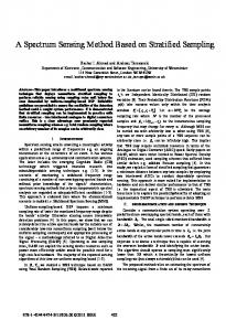
separation radius !1dg is to protect PUs [13], [14]. Thus, it is preferable that the SB may not operate in the area where dsuo < dg. The SN consists of one base station, SB, and Ns SUs (terminals). The radius of the SN coverage is denoted by rc,s' The SUs are assumed to be uniformly distributed within a disk corresponding to the SN coverage area. In a spectrum measurement, the RSS level Rpuo---+su" from the PB transmission at the nth SU, SUn, is given by:
Tpuo - L(dsu,,) + Xpuo---+su",O"x (1) Rpuo---+sun + XPUo---+sun,O"x' dx
=
re,p
The PU locate at the worst case position.
Fig. 1. The network model. The PU is located at the edge of the PB coverage.
but also the link from the PB to the SN. In fact, time domain averaging can suppress the effect of multipath fading in the link from the BP to SN [12], therefore the effect is not considered in this paper. On the other hand, the effect of the muItipath fading in the link from the SB to the PU can not be suppressed, therefore we will investigate the effect of muItipath fading in Tm setting. Numerical results will show that the SN throughput depends on the additional separation radius which is used for protection of PUs. In addition we will show an existence of optimal additional separation radius. We propose the MATP setting method based on coopera tive spectrum measurement to achieve smaller margins. The simulation results verify that the MATP setting method based on cooperative spectrum measurement improves the spectrum utilization compared to the MATP setting using spectrum measurement results only from the SB (MATP setting method based on individual spectrum measurement). II.
where Tpuo is the transmit power of the PB, L(dsun) is path loss in dB, dsun is the distance between the PB and the SUn, XPUo---+SU",O"x reflects the attenuation due to shadowing, and Rpuo---+sun indicates the RSS without the shadowing effect. Note that the index n = 0 is used for base stations. We assume that antenna gains are 0 dBi. We employ the log-normal shadowing model [15] and assume that XPUO---+sun,O"x are independent and identically distributed (i.i.d) normal random variables with zero mean and variance 0';. We assume a standard path loss model with a path loss exponent so that L (d) for given distance d is given by:
L(d)
=
10 10glO
47l'do
( )2 ).
--
+ 107] 10glO
d do
( )'
(2)
where do denotes a reference distance and set to do = 1 m, ). is the wavelength of the carrier frequency, and 7] denotes the path loss exponent. The coverage radii of the PN and the SN, rc,p and rc,s, are set based on the minimum required received signal levels rPN and rSN at the PN and SN, respectively. A interference level Ipu at the PU receiver caused by the SB transmission is given by:
Ipu
SYSTEM MODEL AND ASSUMPTIONS
Tsuo - L(dpu-suo) + Xsuo---+pu,O"x fpu + Xsuo---+pu,O"x'
(3)
The network model shown in Fig. 1 is discussed in Sect. II-A and the MATP setting assuming provided PU location information is explained in Sect. II-B.
where Tsuo is the actual total transmit power of the SB, dpu-SUo is the distance between the PU receiver and the SB, and Xsuo---+pu,O"x is the log-normal shadowing effect in the
A. Network model
link. The constrain probability that the interference caused by the SB exceeds the allowable interference level is given by
As shown in Fig. 1, there are two networks: the PN and the SN. The PN consists of one central control station, such as a base station or broadcasting station, denoted by PB and with PUs corresponding to terminals. Suppose the PN and the SN are in the 2D plane (dx, dy). Static environment is assumed thus, the locations of the PN and SN are fixed. The PN is licensed to operate over a frequency band with bandwidth B. The coverage of the PN is given by a circle with a radius rC,P' with the PB located at the center. The PB and the SB locate at the origin (0, 0) and (dsuo' 0), respectively. A PU receiver located at the edge of the coverage area corresponds to the worst-case scenario [10], i.e., the PU receiver lies at (rC,p ' 0). We define the extended PN coverage dg to consist of the actual coverage and an additional separation radius !1dg such that dg = rC,p + !1dg. The main role of the additional
(4) where Ipu and Ith indicate the interference level and the allowable interference level at the PU, respectively. We set a constraint Pr(Ipu > Ith) ::; Pc, where Pc denotes the CTP. This constraint is used throughout this paper. B. Maximum allowable transmit power setting with provided
location information
To satisfy the CTP, the SB sets a proper Tsuo' In the conventional MATP setting approach, it is assumed that lo cation information (dsuo) is known [6], [7]. We denote this approach by MATP-P, where P stands for "provided location information". In the MATP-P, dpu-suo' is also available at
891
Globecom 2013 - Cognitive Radio and Networks Symposium
SB arrives at a decision by comparing the estimated distance to the distance dg + dm, where dm is a transmission decision margin that is used to guarantee the protection of the PUs when the SB actually resides in the extended PN coverage, i.e. dsuo :s; dg. The protection is guaranteed by setting the dm in such a way that the transmission within the extended PN coverage is allowed with a probability equal or less than the CTP, Pc. The result of this is a binary transmission decision variable, DT, where DT 1 indicates that the transmission is allowed, and DT 0 rejects it. If transmission is allowed, the SB continues to the next step.
Distance estimation
ci;:?, ciii;;
MATP-I: RSS from the SB MATP-C: RSS from the all SUs and SB
1st
step
=
=
Derive MATP using transmit power margin
Fig. 2.
Tm'Z)
2nd
step
In the second step, the SB applies a transmit power margin
Power allocation based on the MATP
Tm that guarantees the PU protection when the SB resides outside the extended PN coverage, i.e., dsuo > dg. The transmit power margin Tm depends on the locations of the PU
A flowchart of the proposed MATP setting procedure.
receiver and the SB corresponding to the transmitter. Since the exact location information is not available at the SB, we set Tm considering the worst case in which the PU receiver lies in the neighborhood of edge of the extended PN coverage and the SB is at a location leading to maximum Tm. This fact will be confirmed in Fig. 3.
the SB since the SB knows r C,p [7]. Given this information, MATP satisfying the constraint can be set as: [7] (P) TSUo,max
=
Ith
+ L(dpu-suo)
(JxQ-1( Pc),
(5)
'
-
A. Distance estimation in MATP-/ and MATP-C
From (1) and (2), dsuo can be estimated with:
�
where the P in T� � ,max indicates the MATP-P, Q-1(X) is the inverse Q-functionand it is assumed that (Jx is known at the SB. The term (JxQ-1( PC) in (5) corresponds to a margin against the shadowing effect in the link from the SB to the PU. III. PROPOSED MATP
SET TING
To satisfy the CTP with unknown distance to the PB, we propose a two-step approach with distance estimation for setting the MATP. A flowchart of this procedure is shown in Fig. 2. The actual problem caused by the unavailability of distance information is shown as follows. In general, the transmit power margin Tm is set based on the worst case scenario, i.e., the SB locates at the edge of extended PN coverage, dsuo dg. In this case, the Tm can satisfy the CP T only when the SB is in the region where dsuo � dg However, the SB may operate in the region where dsuo < dg since estimated distance is used. In this case, the CTP can not be satisfied. For overcoming this problem, the transmission decision with the decision margin is used to protect the PUs. The procedure of the setting the MATP is as follows. The SN first calculates an estimate of the distance. The distance estimation is based on either the RSS value Rpuo--+suo collected by the SB alone (referred to as MATP-I, where I stands for "individual measurement") or the RSS values Rpuo--+suo and RpuO--+sun collected by the SB and N s SUs (n 1, 2", " N s ) (referred to as MATP-C, where C stands for "cooperative measurement"). The SB first decides if transmission is allowed by estimating whether the SB resides within extended PN coverage, dg• The
where the superscript (Z) indicates type of MATP, i.e., (C) for MATP-C and (1) for MATP-I, and A(Z) for MATP-I and MATP-C are
A(I)
Rpuo--+suo, ""Ns L...- n=O RpUo--+su" 1 + Ns
A(C)
(7) (8)
respectively. In the case of MATP-C in (8), RSS values from different SUs are averaged in order to suppress the effect of shadowing.
=
B. Transmission decision with transmission decision margin
The transmission decision rule is defined as:
DT
=
{
1
; O,·
(d(Z) SUo (d(Z) SUo
>
-
dg. According to the transmission decision, the MATP is given by: . A( -1 ( .
y:(Z)
SUo,max _
{
"iO
Z) - re,p ) - axQ (Pc) - TmZ) , + L(dsUo (DT = 1) (11) (DT = 0). No transmission;
Ith
. �:MATP.C, dp=3.nun \ · =--:T 20 1+-----I-+
�
\
,.;: .�
Now we define the constraint probability as a function of the margin T;;) for a given dsuo as Pc(T;;) Idsuo) where the required margin depends on the distance dsuo' Thus, we consider the worst case dsuo when setting the margin. This can be expressed as:
.. :
..
@ 15 �
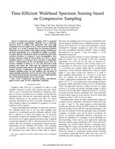
MATP-C is shown in Fig. 3. The parameters are set as N s = 4, 'f/ = 3, ax = 9 dB, re,p = 3.68 km, re,s = 500 m. Values for dg of 3.7 km and 4.2 km are used. In the region where dsuo < dg, the margin d m is used in the transmission decision variable DT, to satisfy the constraint. That is, Pr(DT = 1) � Pc, therefore TJ.,Z) = O. The maximal values are in the region where dsuo ?: dg and close to
dsuo
=
dg. In this region,
.
.. �,,�... .
.
�
. �--�--:-... ...
... ...... .
.
.
.
.
.
.
.
.
Fig. 3. The required margin Tm as a function of dsu o for MATP-C (Ns = 4), and MATP-I, with Pc = 0.01, Ns = 4, 'r/ = 3, ax = 9 dB, re,s = 500 m, re,p = 3.68 km, dg = 3.7 and 4.2 km. 35
p:) �
_
h .
Pr(DT = 1) increases, and to satisfy the constraint, a larger TJ.,Z) is required. In the region to the right of the maximum, T;;) decreases slowly since Pr(DT = 1) » Pc is because
S
::.0 '" a iil � 0 0.
� "
and the far SB transmitter requires smaller transmit power margin. Since the SB does not have exact information about its location dsu0' we set the transmit power margin to the
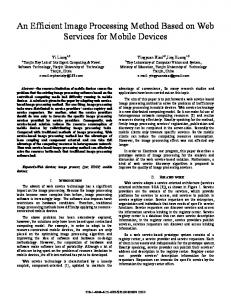
we derive not only Tnf)* considering the shadowing but also T;;)* considering both shadowing and multipath fading. In this paper, block Rayleigh fading model is assumed, thus during one continues transmission the effect of the mUltipath fading is constant. This result shows that smaller values dg require significantly large margins. In the case of the MATP-I, the difference between dg = 3.7km and T;';, at dg = 4.2km is 17 dBm and in the case of the MATP-C the difference is still 15 dBm.
MATP-I,dg = 4.2 km
Distance dsuo [km]
T;;) increases at a rapid rate. This
maximal value, TJ.,Z)* In the case when dg = 3.7 km, the SB may be located near the PU receiver, and thus it requires a significantly large margin. For example, in the case of the MATP-I, TJ.,Z)* = 34 dBm. On the other hand, in the case of the MATP-C with dg = 4.2km, the required margin is only TJ.,Z)* = 5 dBm. The difference between these margins is 29 dBm, and is caused by not only the gain of the cooperative measurement but also by the appropriate dg setting. In Fig. 4, T;';, as a function of dg in terms of the MATP-C and the MATP-I is shown. The parameters are set as N s = 4, 'f/ = 3, ax = 9 dB, re f; = 3.68 km, re s = 500 m. In addition, '
.
�,... .
.
10
(12) To see the worst case for TJ.,Z), (i.e., TJ.,Z)*), TJ.,Z) satisfying Pc as a function of dsuo in the cases of the MATP-I and the
".
�
al .
" "
30
\
\
.\.
25
20
15
10
� o ���----�--� 4 4.2 4.4 4.6 4.8 3.6 3.8
E,dended
PN
coverage dg [km I
Fig. 4. The required transmit power margin T:;" as a function of extended PN coverage dg for MATP-C (Ns = 4), and MATP-I, with Pc = 0.01, 'r/ = 3, ax = 9 dB, re,p = 3.68 km, and re,s = 500 m. The line and marker indicate the result with shadowing and multipath fading, and the only line indicates the result with shadowing.
It is interesting to note that the muItipath fading effect reduces TJ.,Z)* compared to the case only considering shadowing effect. Typically, the margin is set based on the worst case, thus TJ.,Z)* based on only shadowing effect is used in numerical evaluation. IV.
NUMERICAL RESULTS
In this section, MATP-P, MATP-I, and MATP-C are com pared in terms of the average capacity, Cdown similarly as in [7], [8]. In fact, the MATP-P is equivalent to the approach
893
Globecom 2013
-
Cognitive Radio and Networks Symposium
proposed in [7], [8] where perfect location information is assumed to be available. A derivation of the average capacity is shown in the following subsection. The CTP is set to Pc = 0.01. The assumed center frequency of the spectrum band is 600 MHz, which is used in digital TV broadcasting but the application of the proposed method is not limited to it. We set the path loss exponent as T) = 3. The transmit power of the PB is set to Tpuo = 60 dBm and the total transmit power of the SB is always limited to the maximum value of Ttotal = 30 dBm. The minimum required received signal levels, rPN and rSN, are set as -75 dBm and -85 dB, respectively leading to the radii Tc,p = 3.68 km and Te s = 0.5 km. ,
40 35
�
30
';;
25
�
:0
'g g. U
20 IS 10 o
A. Average capacity obtained by Power and channel alloca tion
10
The SB allocates a transmit power Tn,l,mw I for the nth SU transmission on the lth sub-channel, where the bandwidth L sub-channels. The aim of this resource B is divided into allocation is to maximize the down-link capacity Cdown while keeping the interference constraint and a total transmit power constraint. This is expressed as N
max
Cdown =
(
1 s L max L LL
i=l 1=1
)
hn B 2 n l an,l 1og2 1 + N +I h,In,S I BT127',, ,mW /L ' (\3) mW I ,I,P PUo,mW subject to Ns
L an,l :s; 1, Vl, an,l E {O, l}Vn, l,
n=l Ns
(14)
L
L Lai,ITn,l,mW :s; Ttotal,mW,
(15)
n=11=1 Ns
L
L Lai,ITn,l,mW :s; T���,max,mw,
(16)
n=11=1
where an,l is a sub-channel allocation indicator (i.e., an,l = 1 indicates that the lth sub-channel is allocated to the nth SU transmission; otherwise an,l = 0), hn,I,PB denotes the channel gain between the PB and the nth SU for lth sub-channel, and Nmw is the noise power in one sub-channel. The constraints are as follows: (14) indicates that each sub-channel is assigned to only one SU, (15) is the total transmit power constraint due to SB limitations or constraints by a regulator, and (16) is the interference constraint. The variance of channel gain hn,I,PB is determined by the distance between the PB and the nth SU and the log normal shadowing. Without loss of generality, we use capacity normalized by sub-channel bandwidth and L in (l3). The solution of this optimization problem can be found by a simple water-filling scheme as described in [7]. lIn this paper, we use two units, "mW" and "dEm" for variables corre sponding to power values. When unit in a variable is mW, "mW" is noted in the suffix (for example Tn I mW), but when the unit is dBm, notation of unit ' is abbreviated (for exampl� Tn,l) '
15
20
25
Distance dsu" [kill]
30
dg",5km 35
40
Fig. 5. The capacity Cdown as a function of distance dsuo for dg = 3.7 km, dg = 4.2 km, and dg = 5 km. MATP-P, MATP-C (Ns = 4), with Pc = 0.01, 'I) = 3, CTx = 9 dB, re,p = 3.68 km, and re,s = 500 m
The average Cdown is given by Cdown = E[CdownJ. where E[·] denotes the expectation function calculated with respect to channel gains and locations of SUs. Specifically, the locations of SUs in the SB's coverage area follows uniform distribution to calculate Cdown while the channel gains Ihn,I,SB 1 and Ihn,I,PB 1 follows Rayleigh distribution. In addition, we assume that the noise levels per subchannel in the SB and SUs are assumed to be N = -95 dBm. B. Average capacity performances of MATPs
We plot Cdown as a function of dsuo in Fig. 5. To confirm impact of extended PN coverage dg, we plot the Cdown in terms of different dg (dg = 3.7 km, dg = 4.2 km, and dg = 5 km). The result shows that the MATP-C outperform the MATP-I significantly. In addition, Cdown of the MATP-C with dg = 4.2 km achieves the Cdown of the MATP-C in the region where dsuo > 20 km. The gap of Cdown between the MATP C with dg = 4.2 km and the MATP-C in the region where dsuo < 20 km is caused by the distance estimation error. The result also demonstrates that the Cdown also depends on dg. In both the MATP-C and the MATP-I, the case when dg = 4.2 km achieves the best Cdown performance. This indicates an presence of optimum dg. C. Optimum point in terms of extended PN coverage
dg
Average capacity performances depend on the extended PN coverage, dg, as confirmed by the result of Fig. 5. We define Cdown as a function of distance, dsuo, as Cdown (dsuo), and define a new metric to evaluate the MATPs as:
Cdown
=
1
ldsuo=dmax Cdown(dsuo)ddsuo
1 dsuo=rc,p Idmax dmax indicates an assumed _
T
C,p
(17)
where maximum distance. This corresponds to dsuo having uniform distribution in the region
894
-
Globecom 2013
Cognitive Radio and Networks Symposium
coverage range is also important since it significantly affects the average capacity, as was shown by the numerical results. In addition, we demonstrated that there is also an optimum range for the extended PN coverage that can maximize average capacity performance.
105
10 N :t:
] .;§
9.5
1(.)
9
I ��'
,---
�
/Optimum pointinMATP;"r
'"
J
• .
. .
. � �
� �
�
.
REFERENCES � � �
.
•
[I] R. Zhang, Y. C. Liang, and S. Cui, "Dynamic resource allocation in cognitive radio networks," IEEE Signal Processing Mag., vol. 27, no. 3, pp. 102-114, May 2010. [2] L. Musavian and S. Aissa, "Capacity and power allocation for spectrum sharing communications in fading channels," IEEE Trans. Wireless Commun., vol. 8, no. I, pp. 148-156, Jan. 2009. [3] R. Zhang, S. Cui, and Y. C. Liang, "On ergodic sum capacity of fading cognitive multiple-access and broadcast channels," IEEE Trans. Inform. T heory, vol. 55, no. 11, pp. 5161-5178, Nov. 2009. [4] F. F. Digham, "Joint power and channel allocation for cognitive radios," in Proc. IEEE Wireless Communications and Networking Conference (WCNC), Mar. 2008, pp. 882-887. [5] S. Y. Lee, S. H. An, and Y. M. Yoon, "Area spectrum efficiency of TV white space wireless system with transmit power control," in Proc. Inter
� �
I
,
8.5
,
8 L---�--�--� 52 5.4 3.6 3.8 4 42 4.4 4.6 4.8 5 Extended PN coverage dg
Fig. 6.
Cciown
[kml
national Conference on Advanced Communication Technology (ICACT),
as a function of extended PN coverage dg for MATP-C
(Ns = 4) and MATP-I, with Pc = 0.01, 7] = 3, ax = 9 dB, km, re,s = 500 m, and dmax = 40 km.
re,p
[6]
= 3.68
[7]
:s; dsUo :s; dmax. In the evaluation performed here, we use dmax = 40 km. This metric 0down indicates the average of Odown (dsuo) in the dsuo domain. Fig. 6 shows 0down as a function of dg for the MATP-C and the MATP-1. In both cases, the optimum point where 0down is maximized is around dg = 4.2 km. r C,p
V.
CONCLUSION
In this paper, we investigated methods to set the MATP for SS. In our proposed approach, the SB sets the MATP based on an estimate of the distance between the SB and PB (transmitter). We compared against the MATP-P where location information is available at the SB. To satisfy the CTP, the SB has to consider three issues: shadowing from the PB (transmitter) to the SU, shadowing from the SB to the PU receiver, and the lack of location information. To handle these issues, we proposed a two step approach to set the MATP where two margins, the transmission decision margin and the transmit power margin, were employed. The former is to guarantee the protection of the PUs when the SB resides within the extended PU network (PN) coverage, and the latter is to guarantee the PU protection when the SB resides outside of the extended PN coverage. We also investigate the effect of multipath fading especially in the link from the SB (transmitter) to the PU receiver. The results show that in fact multipath fading reduces the required transmit power margin. Numerical results verified our approach and showed that the MATP-I and the MATP-C can satisfy the constraint for any placement of the SN. Furthermore, in the MATP-C, coopera tive measurements are used and the numerical results demon strated that the MATP-C always outperforms the MATP-I in terms of average SN capacity. Setting the extended PN
[8] [9]
[l0] [11]
[l2]
[13]
[14] [15]
895
Apr. 2010, pp. 1061-1066. K. Muraoka, H. Sugahara, and M. AJiyoshi, "Monitoring-based spec trum management for expanding opportunities of white space utiliza tion," in Proc. IEEE Dynamic Spectrum Access Networks International Symposium (DySPAN), May 2011, pp. 277-284. H. Nam, M. B. Ghorbel, and M.-S. Alouini, "Location-based resource allocation for OFDMA cognitive radio systems," in Proc. Cognitive Radio Oriented Wireless Networks & Communications (CROWNCOM), June 2010, pp. 1-5. M. B. Ghorbel, H. Nam, and M.-S. Alouini, "Generalized location based resource allocation for OFDMA cognitive radio systems," in Proc. Wireless Communication Systems (ISWCS), Sept. 2010, pp. 1011-1016. V. Asghari and S. Ai'ssa, "Resource sharing in cognitive radio systems: Outage capacity and power allocation under soft sensing," in Proc. IEEE Global Telecommunications Conference (GLOBECOM), Nov. 2008, pp. 1-5. N. Hoven and A. Sahai, "Power scaling for cognitive radio," in Proc. Wireless Networks, Communications and Mobile Computing, June 2005, pp. 250-255. M. Hong, J. Kim, H. Kim, and Y. Shin, "An adaptive transmission scheme for cognitive radio systems based on interference temperature model," in Proc. IEEE Consumer Communications and Networking Conference (CCNC), Jan. 2008, pp. 69-73. N. Patwari, J. N. Ash, S. Kyperountas, A. O. Hero, R. L. Moses, and N. S. Correal, "Locating the nodes: cooperative localization in wireless sensor networks," IEEE Signal Processing Mag., vol. 22, no. 4, pp. 5469, July 2005. K. Hamdi, Z. Wei, and K. B. Letaief, "Power control in cognitive radio systems based on spectrum sensing side information," in Proc. IEEE International Conference on Communications (ICC), June 2007, pp. 2428. M. Vu, N. Devroye, and V. Tarokh, "On the primary exclusive region of cognitive networks," IEEE Trans. Wireless Commun., vol. 8, no. 7, pp. 3380-3385, July 2009. T. S. Rappaport, Ed., Wireless Communications: Principles & Practice. Prentice Hall. Prentice Hall, 2002.