The electrical characteristics of hafnium oxide (HfO2) films, grown by standard thermal .... Normalized C-V curves of MOS capacitors with 50 nm HfO2 film.
alloys and Co-Cu/Cu multilayers under galvanostatic control from an electrolyte containing CoSO4 and CuSO4. Atomic force microscopy, X-ray diffraction, and ...
P.N.K.D. is grateful for the financial support provided by the. Australian Government Department of Employment, Education,. Training and Youth Affairs.
John E. Fischer,b and Agnes Clayeb. aDepartment of Chemistry ...... 193, Gordon and Breach Science Publishers, Australia 2000. 6. J. S. Xue and J. R. Dahn, ...
poly3-chlorodiphenylamine36 have been reported. Recently, DPA has been copolymerized with aniline37 and benzidine.38 These stud- ies revealed that the ...
Electrodeposited NiFe films from sulfate baths show superior soft magnetic properties ... lower coercivity and higher squareness than from chloride baths.
The dielectric constant of the silica film can be reduced to 1.7 after an HMDS/H2 plasma/HMDS treatment. The leakage current of the plasma-treated silica film ...
strate that the proposed rate control method can more accurately control the ... refer to the sum of the quantization and overhead bits rep- resenting motion ...
all the binary combinations of these five common carbonates: EC, PC, DMC, EMC, DEC. ... binary carbonate systems: propyl
camera, for i 1 to NM , where NM is the number of the testing light. .... (i) ,aM. (i) ,bM. (i)) is the CIELAB coordinate of the ith measured color. From Appendix B and ...
Mn2-doped YF3 and GdF3 were synthesized using a high frequency furnace. In the furnace, the starting materials YF3, GdF3, and MnF2 were in a glassy carbon ...
Receive free email alerts when new articles cite this article - sign up in the ... the Si-rich nitride layer, secondary ion mass spectroscopy study reveals that the.
cJet Propulsion Laboratory, Pasadena, California 91109, USA. Silicon nanoparticle-based floating gate metal oxide semiconductor field effect devices are ...
capacitance of 350 F/g.6 Hydrous ruthenium oxide formed by a sol-gel process yields a .... pressing the paste between two tantalum meshes. Tantalum was.
can be used without modification to data with missing pro- jections or low ... Poisson model and under quadratic approximations to the ... as experimental results show, after only a few updates, the ... represents the scale of the prior .... x i 1. M
Also, free radicals were characterized in aprotic media by electron paramagnetic ... In protic media 30% ethanol/0.1 M Britton-Robinson buffer pH 2-12 2-, and.
good recovery characteristics in the temperature range of 600-1400°C. However, after repeated tests over a longer period, the sensor performance degrades ...
James McBreen,d,** and William H. Smyrla,***,z. aCorrosion Research ..... 356, The Electrochemical. Society Proceedings Series, Pennington, NJ (1999). 21.
MF-1016. Working Electrode, 6 mm Glassy Carbon. MF-1007. Working Electrode,
3 mm Gold. MF-1014. Working Electrode, 3 mm Platinum. CF-2200 Reference ...
Abstract: I examine the recent evolution of the law with respect to repurchase agreements. Repurchase agreements (repo) are short-term debt contracts that ...
V2O5 cathode films for thin film microbatteries*. Han-Ki Kim,a) Young-Woo Ok .... Figure 4d exhibits a HREM image obtained from the 50. W doped film. It can be ...
deficit, while multiple pituitary hormone de- ficiencies are found in 10% of patients. GH/. IGF-I axis was evaluated by GHRH+GHRP-6 test and IGF-I measurement ...
To better understand these experiments and future investigations of high-convergence ICF implosions, the three-dimensional 3-D view-factor code BUTTERCUP ...
Highly parallel data storage system based on scanning probe arrays. M. I. Lutwyche,a) M. ... The magnetic hard disk drive HDD is todays most widely used mass ...
even though the TFB has a high energy density, it may have insuf- ficient power to start some electronic devices, because they often require a peak input power ...
Journal of The Electrochemical Society, 148 共3兲 A275-A278 共2001兲
Thin Film Supercapacitors Using a Sputtered RuO2 Electrode Jae Hong Lim,a Doo Jin Choi,a Han-Ki Kim,b Won Il Cho,c,* and Young Soo Yoonb,z,* a
Department of Ceramic Engineering, Yonsei University, Sodaemoon-ku Seoul 120-749, Korea Thin Film Technology Research Center, cBattery and Fuel Cell Research Center, Korea Institute of Science and Technology, Cheongryang Seoul 130-650, Korea
With advances in thin film process and material engineering, devices have become sufficiently small so as to be arranged on one chip.1,2 As a result, a microenergy source needs to be developed to drive such extremely small size electronic devices. A thin film battery 共TFB兲 is one possibility for satisfying this demand. However, even though the TFB has a high energy density, it may have insufficient power to start some electronic devices, because they often require a peak input power in very short time. Supercapacitors can satisfy this power specification since such devices have a much higher power density than the secondary battery, and thus can supply power in very short time. If the thin film process is applied to the fabrication of supercapacitors, a thin film supercapacitor 共TFSC兲 represents a potentially new micropower source. However, it does not mean that TFB will be replaced by the supercapacitors, but rather that the operation of supercapacitors will be electrically coupled with batteries in charge-discharge processes for on-chip devices. Thin film solid electrolytes are very desirable for the TFSC because their fabrication is based on a thin film process. Thus, the TFSC can be fabricated in an arbitrary shape and any required size in order to satisfy specific electronic requirements. Even though solid electrolytes have a lower ionic conductivity than liquids, the low ionic conductivity of solid electrolytes may be compensated by decreasing the thickness of solid electrolytes in order to reduce the diffusion path of ions such as H⫹, Li⫹, OH⫺, etc. Pseudocapacitors utilize conducting metal oxides 共RuO2, 3,4 IrO2, Co3O4, 5 etc.兲6 or polymer electrodes.7 Among the possible metal oxides for pseudocapacitor electrodes, RuO2 has advantages of a wide potential range of highly reversible redox reaction,8 high capacity,3,4 and a metallic type conductivity. However, it is expensive for commercial use as the electrodes in bulk-type supercapacitors. Therefore, the application of a thin film process to the fabrication of supercapacitors can exclude this drawback. To date, electrolytes in supercapacitors are liquid-state such as sulfuric acid, KOH, etc.3-6 However, these liquid electrolytes cannot be used at high temperatures, because they undergo decomposition. In addition, the leakage current and ionic conductivity vary significantly with temperature variation. Therefore, when fitted with solidstate electrolytes, the TFSC has advantages such as negligible leakage current and a wide operational temperature range. Lix POy Nz 共Lipon兲9,10 has a wide electrochemical stability window of about 5.5 ⫾ 0.2 V at room temperature and is mechanically stable. Thus, it is possible to cycle a cell up to about 5 V, and to avoid cracks in
the Lipon during cycling because of the volume change of electrodes. Therefore, an amorphous Lipon film, a Li ion conductor, was deposited as a solid-state electrolyte in order to develop an all solidstate TFSC. In this paper, we present data on a solid-state TFSC, which is based on RuO2, a thin film electrode, and a Lipon thin film electrolyte. All films were deposited by sputtering methods. The chargedischarge performance of a single cell with RuO2 /Lipon/RuO2 /Pt structure was demonstrated and an Auger electron spectroscopy 共AES兲 depth profiling technique was carried out to characterize the extent of Li ion diffusion in the RuO2 film. Experimental The RuO2 electrode film was deposited on a Pt/Ti/Si substrate by means of a specially designed dc reactive sputtering system. Figure 1 shows the schematic features of TFSC. The Ti thin film was deposited as an adhesive layer by a radio frequency 共rf兲 sputtering method on a Si wafer. The Pt film was grown on a Ti film as a current collector to diminish potential drop between electrode and collector, and to apply voltage to the electrode uniformly. The sputtering target was a 4 in. Ru metal target 共purity 99.99%, Super Conductor Material Inc.兲. The Ru metal target was presputtered by an Ar ion plasma to eliminate the surface oxides and/or contamination for 20 min prior to the deposition of the RuO2 film. The RuO2 film was grown as a bottom electrode over the Pt current collector film by reactive sputtering in an Ar/O2 共ratio: 70/30兲 atmosphere at room temperature. The applied dc power was 100 W. The constant working pressure for all film deposition was maintained at 5 mTorr. Subsequently, the Lipon film was deposited on the as-deposited RuO2 film by an rf sputtering method. The Li3PO4 target was sputtered with the rf power of 300 W in a pure N2 ambient to grow the Lipon film. The flow rate of N2 was maintained at 50 standard cubic centimeters per minute 共sccm兲. After the deposition of the electro-
Figure 1. A cross-sectional diagram of an all-solid-state thin film supercapacitor on silicon substrate.
A276
Journal of The Electrochemical Society, 148 共3兲 A275-A278 共2001兲
Figure 2. SEM surface photograph of an as-deposited RuO2 film.
lyte, the deposition of the RuO2 top electrode film was achieved by the same conditions used for the bottom electrode as described above. Rutherford backscattering spectrometry 共RBS兲, inductively coupled plasma atomic spectroscopy 共ICP兲 and X-ray diffraction 共XRD, Rigaku, 20B diffractometer with Cu K radiation兲 measurements were employed to investigate the stoichiometry and crystallinity of the as-deposited film, respectively. Scanning electron microscopy 共SEM, Hitachi, S-4100兲 was employed to observe the surface and the cross section morphology. The charge-discharge measurements at constant current were carried out in a WBCS3000 共Wonatech兲 cycler. The constant current density and cutoff voltage range were 100 A cm⫺2 and 0-2 V for the RuO2 /Lipon/RuO2 /Pt structure supercapacitor, respectively. Li ion distribution in RuO2 film was measured by AES 共PHI-670兲. The AES depth profile result was obtained using Ar ion sputtering at an ion energy of 3 keV and an incident beam angle of 30° to the normal to the surface. Results and Discussion SEM analysis was employed to investigate the surface morphology of RuO2 film. Figure 2 shows the surface of the RuO2 film, which indicates the absence of large defects, such as grooves and/or voids. This smooth and dense surface plays an important role in the growth of a Lipon film, having a smooth interface between the RuO2 film and the Lipon film, because the solid electrolyte is deposited in this area in a subsequent step. If, for example, defects exist on the surface of the as-deposited electrode film, these defects will affect the surface morphology of the electrolyte film and can result in poor contact with the thin film electrolyte. Therefore, it is imperative to obtain a smooth surface electrode, to achieve high performance TFSC. Figure 3 shows an XRD profile of the as-deposited RuO2 film along the surface normal direction. There is a 共400兲 peak from the Si substrate and no indication of any crystalline phase in the RuO2 films. XRD results indicate that the film grown on the Si substrate has amorphous characteristics. It is known that the proton involved reaction of RuO2 film is strongly dependent on the structure of the RuO2 phase in an electrochemical capacitor using aqueous electrolyte.5 The crystal structure of the RuO2 phase cannot expand the RuO2 lattice and accept mobile ions, whereas an amorphous RuO2 film structure is relatively adaptable in terms of the intercalation-deintercalation of ions, such as H⫹ and OH⫺. This might be the same case on the TFSC using the Li ion electrolyte. Therefore, the growth of an amorphous RuO2 film is more desirable than the growth of a crystalline phase in fabricating a durable TFSC.
Figure 3. XRD pattern of an as-deposited RuO2 film.
The film thickness, as determined from the Alpha step, was about 0.3 m, and this value is consistent with SEM results. The composition of the electrode film deposited on graphitedeposited Si substrate was determined using RBS to obtain the O/Ru ratio. An example of an RBS spectrum is shown in Fig. 4; the solid line is the simulated backscattering from which the O/Ru ratio was obtained. The O/Ru ratio, as determined by RBS was 2.05. Therefore, the as-deposited ruthenium oxide is, in fact, a RuO2 phase. The surface SEM of an as-deposited Lipon film is shown in Fig. 5. The smooth surface of the Lipon electrolyte film plays an important role in the deposition of the top RuO2 film, as mentioned in the deposition of the bottom RuO2 electrode. The Lipon electrolyte film does not have a channel connected from the top to the bottom side, and therefore, it is able to block the electron movement between both electrodes. To take a simple example, if a channel is connected from the top to the bottom side and electron current flows through the channel of the Lipon film, the leakage current occurs during charge-discharge steps. Therefore, the deposition of a smooth film with no defect in the electrolyte is important in order to guarantee
Figure 4. RBS spectra for a RuOx film deposited with an O2 /Ar ⫹ O2 flow ratio of 30% and a dc power of 100 W.
Journal of The Electrochemical Society, 148 共3兲 A275-A278 共2001兲
A277
Figure 7. Cyclability of thin film supercapacitor in the potential range between 0 and 2 V. The current density was 100 A cm⫺2. Figure 5. SEM surface photograph of an as-deposited Lipon film.
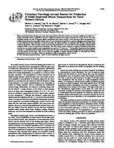
the high performance of the TFSC. The film composition was determined by ICP and RBS to measure the ratios of Li/P, and N/O/P, respectively. The composition of Lipon film was Li2.81PO3.1N0.7. The charge-discharge behavior of the RuO2 /Lipon/RuO2 TFSC was examined under a constant current 100 A cm⫺2 between 0 and 2.0 V. The charge-discharge curve for the RuO2 /Lipon/RuO2 TFSC at room temperature is shown in Fig. 6. Li ions were inserted into the negative electrode during charge, and Li ions were extracted from the negative electrode during discharge. The charge-discharge behavior was similar to that of a bulk-type supercapacitor.5-7 However, the current-resistance 共IR兲 drop was larger than that observed in aqueous electrolytes. The origin of IR drop might be from the resistance to ion mobility of the Lipon electrolyte film. The activation energy of the as-deposited Lipon film was 0.58 ⫾ 0.02 eV, yielding the ionic conductivity of 1.02 ⫻ 10⫺6 S/cm at 298 K. The charge responses are not symmetric to their corresponding discharge responses. The major cause of this nonsymmetrical curve is due to slow diffusion of Li ions. During discharge process, slow diffusion of Li ions into Lipon electrolyte film and RuO2 films leads to the polarization at the interface of the electrode and the electrolyte. Capacitance vs. cycle curve of the TFSC is shown in Fig. 7. The capacitance per volume of RuO2 /Lipon/RuO2 /Pt TFSC was about 38 mF/cm2 m. After 500 cycles, the charge-discharge efficiency dropped by 53% with respect to the first cycle. A cycle life of 550 cycles was demonstrated. At the first charging stage, Li ions are
Figure 6. The voltage as function of time during a charge-discharge cycle for thin film supercapacitor with RuO2 /Lipon/RuO2 /Pt structure.
transported to the negative electrode. It is considered that the redox reaction on RuO2 TFSC devices involves Li ion insertion between positive and negative electrode. At the positive electrode, the oxidation state of Ru ion became higher. The reactions at each electrode since the second charging stage can be presented as follows Positive electrode charge
xLi•RuO2 RuO2 ⫹ xLi⫹ ⫹ xe discharge
Negative electrode charge
RuO2⫺y ⫹ xLi⫹ ⫹ xe xLi•RuO2⫺y discharge
If all Ru⫹4 ions in the RuO2 film were reduced to Ru⫹2 ions, x in the above reaction would be 2. Under this assumption and a cutoff voltage of 2 V, the calculated capacitance is 656.57 F/g 共457.6 mF/cm2 m兲. However, in this experiment, the resulting capacitance at the first cycle was about 38 mF/cm2 m, about 8% of the calculated value. The reason for this low capacitance can be attributed to the fact that the Li ions in the Lipon film are not sufficient for the redox reaction of the RuO2 films. Therefore, Li ion transfer process is not fully involved in the oxidation state changes of Ru⫹2 to Ru⫹4. The capacitance per volume of RuO2 /Lipon/RuO2 /Pt TFSC was drastically decreased. The capacitance fade was caused by formation of a second phase in the RuO2 film and the solid phase diffusion. The as-deposited RuO2 film had a slight excess of oxygen ions from the RBS spectrum. Excess oxygen atoms are able to trap lithium ions11,12 and this trapping is related to the accumulation of lithium during long term cycling of electrodes.13,14 Therefore, inserted Li ions react with excess oxygen resulting in Li2O in the RuO2 matrix. The solid phase diffusion produces partial solid solution at interface between the electrode and the electrolyte, which degrades these films. That causes mobile ions to be largely impeded at the phase boundary and the contact resistance increases. To verify the presence of Li2O in the RuO2 film and the solidstate diffusion at the interface after the charge-discharge process, an AES depth profile of TFSC was obtained and is shown in Fig. 8. As for the as-fabricated TFSC, there is no obvious evidence for any diffusion between the RuO2 and Lipon films in Fig. 8a. Oxygen is rich on the surface of RuO2 film before charging and discharging process. Li ions diffuse into the RuO2 film to produce Li2O on the surface after the first charge-discharge process. This is evident from the Auger spectral data 共Fig. 8b兲. This indicates that when the RuO2
A278
Journal of The Electrochemical Society, 148 共3兲 A275-A278 共2001兲 Li2O. At the interface of RuO2 and Lipon films, there seems the formation of the solid solution by the diffusion. With continued cycling, the amounts of Li ions that are exchanged decreased slowly. Hence, the capacitance decreases with subsequent cycles.
Conclusion An all solid-state TFSC was fabricated by means of dc reactive sputtering and rf sputtering methods. The charge-discharge curve of RuO2 /Lipon/RuO2 /Pt TFSC was comparable to those of bulk supercapacitors. Nonlinear discharge curve is due to the polarization at the electrode/electrolyte interface. This poor reversibility results in a capacitance fade that is larger than that of bulk supercapacitors. The main reasons for capacitance fade are that the excess oxygen ions in the RuO2 film can serve as lithium ion trap sites, and the formation of the solid solution by the diffusion can impede Li ion insertion into RuO2 films. Therefore, the deposition of stoichiometric RuO2, and the utilization of abundant mobile ions in the electrolytes and high ionic conductivity may be important for high performance supercapacitors. References
Figure 8. AES depth profile of various elements of the RuO2 film in a thin film supercapacitor. 共a兲 In an as-fabricated TFSC, 共b兲 after the first chargedischarge process.
film is charged, the Li ions diffuse into the other topside of the RuO2 film and the diffused Li ions react with the excess oxygen ions in the RuO2 film as a trap site for Li ions, thus producing the by-product of
1. Y. S. Yoon, J. H. Kim, A. M. Schmidt, D. L. Polla, Q. Wang, W. L. Gladfelter, and Y. H. Shin, J. Mater. Sci.: Mater. Electron., 9, 465 共1999兲. 2. Y. S. Yoon, J. H. Kim, D. L. Polla, and Y. H. Shin, Jpn. J. Appl. Phys., 37, 7129 共1998兲. 3. H. B. Sierra Alcazar, K. A. Kern, G. E. Mason, and R. Tong, in Proceedings of the 33rd Power Sources Symposium, Cherry Hill, NJ, June 13-16, 1988, The Electrochemical Society, Inc., p. 607 共1988兲. 4. J. P. Zheng, P. J. Cygan, and T. R. Jow, J. Electrochem. Soc., 142, 2699 共1995兲. 5. L. M. Da Silva, J. F. C. Boodts, and L. A. DeFaRia, Electrochim. Acta, 45, 2719 共2000兲. 6. B. E. Conway, Electrochemical Supercapacitors, p. 15, Kluwer Academic Publishers, New York 共1999兲. 7. J. P. Zheng, T. R. Jow, Q. X. Jia, and X. D. Wu, J. Electrochem. Soc., 143, 1068 共1996兲. 8. T. Liu, W. G. Pell, and B. E. Conway, Electrochim. Acta, 42, 3541 共1997兲. 9. S. Sarangapani, B. V. Tilak, and C. P. Chen, J. Electrochem. Soc., 143, 3791 共1997兲. 10. X. Yu, J. B. Bates, G. E. Jellison, Jr., and F. X. Hart, J. Electrochem. Soc., 144, 524 共1997兲. 11. T. J. Vink, E. P. Boonekamp, and R. G. F. A. Verbeek, J. Appl. Phys., 85, 1540 共1999兲. 12. R. C. Agrawal and R. K. Gupta, J. Mater. Sci., 34, 1131 共1999兲. 13. S. Hashimoto and H. Matsuoka, J. Electrochem. Soc., 138, 2405 共1991兲. 14. S. Hashimoto and H. Matsuoka, Surf. Interface Anal., 19, 464 共1992兲.