Melissa Orme,a) Jon Courter, Qingbin Liu, Changzheng Huang, and Robert Smith. Department of Mechanical and Aerospace Engineering, University of ...
PHYSICS OF FLUIDS
VOLUME 12, NUMBER 9
SEPTEMBER 2000
Electrostatic charging and deflection of nonconventional droplet streams formed from capillary stream breakup Melissa Orme,a) Jon Courter, Qingbin Liu, Changzheng Huang, and Robert Smith Department of Mechanical and Aerospace Engineering, University of California, Irvine, California 92697-3975
共Received 31 December 1998; accepted 1 June 2000兲 Droplet streams generated from capillary stream breakup and forced with amplitude-modulated 共a-m兲 disturbances will undergo a systematic interdroplet merging process due to their relative velocities that result from the a-m disturbance. This paper concerns the electrostatic charging of droplets generated with a-m disturbances, and seeks an understanding between the competitive effects of the electrostatic repulsive force and the momentum associated with relative velocities that are due to the a-m disturbance. To this end, experimental results and numerical simulations that are in excellent agreement and predict the configuration of the charged droplet stream are presented. In this work, droplets are generated with the aforementioned technique and are electrostatically charged. It has been found that for droplets generated with a disturbance with a high degree of modulation, m, the momentum of the droplets dominates over the electrostatic force causing the droplet merging process to be similar to the uncharged case as attested by both experimental results and numerical simulations. Here, m is the ratio of modulation to original carrier amplitudes. For droplets with lower values of m, the electrostatic forces dominate and it is found that the relative positions of the droplets will oscillate along the direction of their flight path with maximum excursions not exceeding one wavelength of the carrier disturbance 共i.e., the separation of the unmerged droplets兲. © 2000 American Institute of Physics. 关S1070-6631共00兲00709-1兴
共chosen to be at or near the wave number of maximum growth rate in the Rayleigh regime兲 and modulation frequency respectively. If R is the ratio of the carrier frequency to the modulation frequency, c / m , the frequency components are R, R⫹1, and R⫺1 times the modulation frequency, where R can assume either integer or noninteger values. If R is an integer then the final configuration of droplets will consist of uniformly separated sized drops with radii equal to r c R 1/3, and center-to-center separations of R, where r c and are the radius and wavelength associated with droplets generated from a conventional forcing disturbance with frequency c . To generate streams of droplet patterns characterized by different sized droplets at different separations, R can assume any noninteger value. The resulting droplet sizes and interdroplet separations can be predicted in exact order of occurrence.9,10 The different sized droplets should not be confused with ‘‘parent’’ and ‘‘satellite’’ droplets, where the parent drops are the main drops generated with conventional forcing disturbances and the satellite drops are smaller drops that appear in between the parent drops. In nonconventional droplet formations generated with a-m disturbances, the smallest droplets are the size of a conventional parent droplet, and the larger drops result from controlled merging of several parent drops. Furthermore, the final droplet stream configuration is viewed on the order of 1500 drop diameters downstream of the capillary stream breakup location which is well beyond the distance at which the satellites will merge with the parent drop. Use of nonconventional droplet forma-
I. INTRODUCTION
The ability to accurately deliver electrostatically charged and deflected droplets has been the subject of many experimental investigations, most of which date from the early 1960’s due to the advent of the ink-jet printing technology.1–4 Those works detailed many careful experiments and described comprehensive theories of droplet charging and deflection for conditions applicable to ink-jet printing. Recently, significant interest has been directed towards the area of molten droplet based net-form manufacturing,5–7 and electronics packaging applications.8 These important emerging applications rely on the deposition of precisely controlled droplets. The flexible generation of nonconventional droplet formations and the associated electrostatic charging and deflection is the focus of this paper and has direct application to the aforementioned emerging technologies. Nonconventional droplet streams are generated from capillary stream breakup using amplitude-modulated 共a-m兲 disturbances, and refer to droplet streams that have either extended wavelengths and droplet sizes over those that can be uniformly generated with conventional forcing disturbances 共single frequency disturbances in the Rayleigh regime兲, or have predictable sequences, or patterns, of droplet sizes and separations. The a-m disturbance can be decomposed into the following three frequency components: c , ( c ⫹ m ) and ( c ⫺ m ), where c and m are the carrier a兲
Author to whom correspondence should be addressed.
1070-6631/2000/12(9)/2224/12/$17.00
2224
© 2000 American Institute of Physics
Phys. Fluids, Vol. 12, No. 9, September 2000
Charging and deflection of nonconventional droplet streams
2225
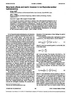
FIG. 1. Example of molten solder droplet streams with 共a兲 no amplitude modulation, 共b兲 R⫽2, m⫽50%, 共c兲 R⫽3, m⫽50%. Carrier frequency and orifice diameter is 12 000 Hz and 100 m, respectively, in each case.
tions in droplet-based manufacturing applications is attractive for two reasons: 共1兲 the droplet streams can be ‘‘customized’’ in order to achieve a selected microstructure of the net-formed component; 共2兲 a higher degree of flexibility of droplet sizes and separations can be achieved from a single orifice size than with conventional droplet production methods 共see Sec. II below兲. The droplets generated with a-m disturbances are termed ‘‘nonconventional’’ since the limiting restrictions in droplet sizes and separations that are associated with the conventional Rayleigh mode of droplet formation are removed. The generation of nonconventional droplet formations require that the monodisperse droplets that initially define the droplet stream merge during flight with their nearest neighbors in a systematic and controlled manner. Figure 1 illustrates three different uncharged solder droplet streams emanating from a 100 m diam orifice. In the first photograph 1共a兲, the droplets were generated with a conventional sinusoidal disturbance with a carrier frequency of 12 000 Hz. In photograph 1共b兲, an amplitude-modulated signal was applied with a carrier frequency of 12 000 Hz and a modulation frequency of 6000 Hz, i.e., a frequency ratio, R, of 2. It can be seen that the jet initially forms into carrier droplets, but then merges in flight to form modulation drops that are separated by a wavelength associated with the modulation frequency. The third photograph 1共c兲 similarly illustrates the situation in which an amplitude-modulated disturbance with a frequency ratio of 3 is applied to the stream. Again, the carrier frequency is 12 000 kHz. In both photographs 1共b兲 and 1共c兲 the degree of modulation, m, is 50%. This merging phenomenon occurs due the characteristics of the forcing disturbance applied to the capillary stream that initiates droplet breakup and coalescence, which is discussed in detail in the aforementioned references and reviewed in brevity in the next section. Figure 2 illustrates a photograph of a droplet stream with an interdroplet configuration of ‘‘large–small–large’’ which was achieved by imposing an amplitude-modulated disturbance with a frequency ratio of 3.5 and a degree of modulation, m, of 50%. The smaller droplets are not satellite droplets as
FIG. 2. Example of the evolution of a molten solder droplet stream with a repeatable pattern of large–small–large droplets which was generated with a frequency ratio, R, of 3.5 and a degree of modulation, m, of 50%.
discussed above, but are the same size as the droplets generated with a conventional 12 000 kHz disturbance, and hence are ‘‘unmerged’’ carrier droplets. The droplet configurations illustrated in Figs. 1 and 2 are completely stable. Previous work analyzed the stability of the configurations similar to those shown in the figures by time-series analysis that contained upward of 1000 drops.10 The details of the interdroplet merging process are affected when the precoalesced droplets are electrostatically charged. The information that specifies the merging characteristics and final configuration of the droplet formation is coupled in the details of the forcing waveform utilized for droplet generation and the charge applied to each drop. Before these details can be discussed, it is necessary to provide a brief overview of conventional droplet formation. II. BACKGROUND A. Droplet formation from capillary stream breakup
Droplet formation from capillary streams is typically achieved with the well-known Rayleigh instability. In practice, a controlled periodic disturbance is initiated on the surface of the jet by means of a mechanical vibration such as that resulting from motion of a piezoelectric crystal. When the stream conditions are such that the nondimensional wave number, k 0* , defined by the ratio of the initial stream circumference to the wavelength of the imposed disturbance is less
2226
Orme et al.
Phys. Fluids, Vol. 12, No. 9, September 2000
than unity, the periodic vibration will translate to an unstable radial disturbance on the surface of the jet which grows until droplets are pinched from the stream. Lord Rayleigh11 showed that the surface waves grow exponentially in time as e  t , where  is the growth rate for a viscous fluid given by Weber12 as
 2⫹
3 k 0* 2 r 20
⫽
V 0 a k 0* 2 K 0 共 k 0* 兲 2 2 * * 1⫺k k ⫹ , 兲 共 0 0 2 r 30 2r 20 K 1 共 k 0* 兲 共1兲
where K n is the nth order modified Bessel function of the second kind, r 0 is the unperturbed stream radius, a is the density of the ambient fluid, is the kinematic viscosity of the fluid, is its surface tension, and k * 0 is defined above. Equation 共1兲 predicts that the surface disturbance on a capillary stream is unstable and results in droplet formation for k* 0 ⬍1, which agrees with experimental observations. Equation 共1兲 also predicts that there is a maximum  at a given k* 0 , denoted here as k 0* max . Recent experimental studies have been devoted to the production of uniformly sized droplets and on the nonlinear effects of capillary growth.13–18 Many theoretical investigations have focused on the development of the nonlinear theory of the instability of an inviscid jet.19–26 Studies of capillary breakup time and the determination of the fastest growing wave number of the stream’s disturbance when forced with a sinusoidal disturbance have often been the primary focus of the previous work. More details concerning the breakup of liquid jets into droplets can be found in the excellent review articles by Bogy27 and McCarthy and Molloy.28 Studies of the behavior of the droplets after a significant travel distance have been, for the most part, avoided. The droplet generation technique defined by the Rayleigh instability is termed ‘‘continuous’’ droplet generation since a capillary stream is broken into a continuous stream of droplets. Shield et al.29 and Bousfield et al.30 have developed techniques of generating droplets at given pulses and thus are termed as drop-on-demand. The drop-on-demand mode of droplet generation is limited by lower droplet production rates than the continuous mode. Chaudhary et al.31–33 used a sinusoidal disturbance with an added harmonic to study the merging of satellite droplets. Additionally, Scheller and Bousfield34 used a nonsinusoidal disturbance to study the direction of satellite droplets. Huynh et al.35 also theoretically studied the instability of capillary jets subject to sinusoidal disturbances with added harmonics and found that a variety of droplet sizes and shapes could be generated at the time of droplet formation. Their simulations predict a variety of non-intuitive droplet shapes that occur at the time of formation, which could have practical value in applications that require the droplets to freeze instantly. In the applications that drive the current work, however, the molten metal droplets do not freeze immediately, but rather relax into a spherical form before they freeze, thereby losing their initial shape characteristics. A sinusoidal disturbance with an added harmonic is fundamentally different from an amplitude modulated 共a-m兲 disturbance, which is the subject of this work, and results in
markedly different droplet generation behavior when imposed on the capillary stream. Since an a-m disturbance has the general form of (1⫹m sin mt)sin ct, it can be decomposed into three frequency components, c , c ⫹ m , and c ⫺ m . In the above, m is the degree of modulation 共i.e., the ratio of the modulation amplitude to the original carrier amplitude兲, c is the carrier, or fundamental, frequency chosen to be in the region of maximum amplitude growth rate in the Rayleigh regime, and m is the modulation frequency. Hence, as harmonic components are characterized by frequencies that are exact multiples of the fundamental frequency, the a-m waveform is characterized by frequency components that are R⫺1, R, and R⫹1 times the modulation frequency, where R can be either an integer or non-integer. The droplet configurations shown in Figs. 1 and 2 cannot be achieved with a conventional sinusoidal disturbance, or a sinusoidal disturbance with an added harmonic, but are only achieved with an a-m disturbance as described above. Previous work by Orme36 showed that the droplet stream is most uniform 共e.g., has less velocity dispersions兲 when perturbed with a disturbance at or near k 0* max , where k 0* max is the nondimensional wave number that is associated with the maximum growth rate. Stream generation at k 0* ’s significantly different than k 0* max lead to much higher speed dispersions 共up to two orders of magnitude higher兲. Thus, when using conventional Rayleigh-mode droplet formation, the droplet production frequency and droplet diameter are strictly coupled with the orifice diameter and stream speed. Droplet generation at k * 0 ’s near k 0* max allows a small range of droplet diameters and frequencies for uniform droplet production. B. Droplet generation at extended wavelengths
1. General phenomenon
In order to increase the flexibility of droplet formation from capillary stream breakup, the forcing disturbance that has the form of an amplitude-modulated waveform can be applied. Use of the a-m disturbance will extend the droplet separation and droplet diameters beyond that allowed by the conventional Rayleigh breakup as discussed above, or will allow the ability to customize the droplet stream to be composed of more than one droplet size at predictable separations. When using a-m disturbances for droplet generation, the fast, or ‘‘carrier’’ frequency, c , is given by Rayleighmode breakup as described above and is selected to have a nondimensional wave number near k 0* max . The modulation frequency is either an integral multiple of the carrier frequency for the generation of ultra uniform droplets at extended wavelengths 共such as that shown in Figs. 1兲, or a nonintegral multiple for the generation of controlled polydispersed droplets which have been termed ‘‘droplet patterns’’ such as that shown in Fig. 2. It is interesting to note that generation of droplet streams with the same physical characteristics as those shown in Figs. 1 and 2 is impossible without the imposition of a-m disturbances. For the case of uniformly separated droplets, the equivalent nondimensional wave number k 0* which would be needed to generate the streams depicted with a
Phys. Fluids, Vol. 12, No. 9, September 2000
single frequency sinusoidal disturbance would be out of the range of k * 0 ’s for uniform droplet formation yielding a highly irregular droplet stream with a random distribution of sizes and separations. The effective nondimensional wave number, k 0* eff of the final configuration of drops is equal to k 0* /R, where the k 0* eff is the wave number that would be required to generate the resulting streams with a conventional single frequency disturbance. In fact, the droplet streams generated with a-m disturbances are more uniform than the conventional Rayleigh mode droplets. Orme et al.9 found that the speed dispersion of amplitude-modulated disturbances decreases as 1/R, where R is the frequency ratio of the a-m disturbance. Although the general phenomenon of droplet generation with a-m disturbances is discussed in detail in previous work,9,10 a brief overview will be included here in order to present a cohesive model of charge interactions between droplets generated with amplitude-modulated disturbances 共see Sec. III below兲. 2. Prediction of nonconventional droplet configurations
When a fluid stream is perturbed with an a-m disturbance whose carrier frequency is in the range of Rayleigh growth 共i.e., k 0* ⬍1兲, the disturbance will be unstable and initial droplets will be formed with sizes and separations commensurate with the carrier disturbance, and hence are termed ‘‘carrier’’ droplets. Unlike conventional droplet formation, however, each of the n droplets initially formed have relative velocities, ⌬u n , that result from the asymmetry of the radial amplitudes of the front and back extremes of the potential drop due to the asymmetric amplitude of the forcing disturbance. When R is an integer, the relative velocities cause the droplets to merge systematically with their neighbors, resulting in ‘‘modulation’’ drops that are characterized by masses and wavelengths that are R times that of droplets generated with only the carrier disturbance as shown pictorially in 共b兲 and 共c兲 of Fig. 1. With knowledge of the characteristics of the forcing disturbance 共e.g., c , m , m, and phase relationship between the two waveforms兲 the merging time can be predicted with excellent agreement with experimental observations.9 When R is not an integer, droplet patterns are formed such as those shown in Fig. 2. In this case, the smaller droplets correspond to the unmerged ‘‘carrier’’ droplets and the larger drops result from systematic merging of several carrier drops. In this work, we investigate the interactions between electrostatically charged droplets undergoing the transition between ‘‘carrier’’ droplets to ‘‘modulation’’ drops or to droplet patterns due to the imposition of an a-m disturbance. When the droplets are generated with a-m disturbances and are electrostatically charged, they will possess two relative ˜ n , where the former revelocity components, ⌬u n and ⌬u sults from the asymmetry of the perturbation waveform as described above, and the latter is due to mutual droplet charge interactions and will be discussed in greater detail below. The estimation of ⌬u n is based on Rayleigh’s linear theory that states that the stream’s radius r(t) grows expo-
Charging and deflection of nonconventional droplet streams
2227
nentially in time. Using the transfer function that relates the time varying pressure disturbance p(t) to the radial perturbation on the stream has been shown to give adequate estimates of the impulse exerted on the stream,9 r共 t 兲 ⫽1⫾ 兵 关 p 共 t 兲 /p 0 兴 1/4⫺1 其 e  t , r0
共2兲
where the time varying amplitude-modulated pressure disturbance is imposed of the form, p 共 t 兲 ⫽ p 0 ⫹⌬p 共 1⫹m sin m t 兲 sin c t,
共3兲
where p 0 is the pressure that drives the mean fluid flow through the orifice, ⌬ p is the amplitude of the fluctuating pressure disturbance, m is the degree of modulation of the waveform, m and c are the modulation and carrier frequencies, respectively, so that the frequency ratio, R, is equal to c / m . The impulse exerted on each drop as a result of the disturbance has been estimated by using a momentum balance and conservation of mass. The analysis is similar to that used by Goedde and Yuen15 to predict the velocity of contraction of a fluid ligament. In this case, the momentum balance is applied about the remaining necking point of a drop to be formed. With the assumption that the pressure of the liquid at the break points is dominated by surface tension, the relative speed of each droplet can be estimated from ⌬u n ⫽
1 mn
冕
tb
tb
n⫹1
r 共 t 兲 dt,
共4兲
n
where m n is the mass of the nth droplet and t b n and t b n⫹1 are the break times at both extremes of the potential droplet. Substitution of Eqs. 共2兲 and 共3兲 into Eq. 共4兲 and carrying out the integral for a series of droplets within one repeatable droplet pattern allows the determination of the relative speed component of each droplet. The break times t b n are estimated to occur when r(t) is equal to zero. Complete details of the assumptions made in deriving Eq. 共4兲 are provided in Ref. 9. III. DROPLET CHARGING AND DEFLECTION A. General phenomenon
Charging and deflection of ink droplets for application to ink-jet printing has been examined in detail by Sweet,1 Schneider et al.,2 Kamphoefner,3 and Fillmore et al.4 In an electrostatic ink jet printer, characters are produced by deflecting charged droplets along one axis while the print head moves along the perpendicular axis. The droplet charge and the strength of the electric field through which the droplet moves determine the amount of deflection achieved by a droplet. The net charge on the droplet is acquired at the time of droplet formation. In this work, molten solder droplets are charged and deflected in a manner similar to ink droplet deflection described above. The difference between the previous works aimed at inkjet printing and the work described here is twofold. First, droplet streams in this work are manipulated with the use of a-m disturbances to form nonconventional droplet separations and patterns that are characterized by either extended
2228
Orme et al.
Phys. Fluids, Vol. 12, No. 9, September 2000
FIG. 3. Schematic of experimental set-up.
wavelengths, or by predictable sequences of droplet sizes and separations. Systematic coalescence of the neighboring droplets forms the patterns. When the droplets are electrostatically charged the coalescence characteristics can be radically altered if not eliminated entirely. Second, the droplets are charged with significantly higher charges so that large horizontal surfaces can be ‘‘printed’’ with molten metal droplets thereby fabricating a structural component. For significant levels of droplet charge, significant interdroplet mutual electrostatic interactions will occur which are not evident in the ink-jet printing technology. Liu et al.37 have recently shown that electrostatic interactions in closely spaced and highly charged droplet streams cause the droplets to move laterally out of the stream, causing a zigzag effect and degrading the printing accuracy. Charge conditions for which this phenomenon occurs are provided in the aforementioned reference. Figure 3 illustrates a conceptual schematic of the droplet generation, charging and deflection apparatus. Molten metal droplets are charged by electrostatic induction. The molten metal jet passes through the charge electrode which surrounds the jet at the point of droplet formation. The conductive molten liquid is grounded and a positive periodic potential, V c , is applied to the charge electrode as shown. As drops are formed from the continuous column of molten metal, a negative charge is induced on the drop that is proportional to the charge potential. In order to print the droplets to different locations, a distinct potential is applied to the
charge electrode for every drop to be formed, and therefore, synchronization between the charge waveform frequency and the droplet production frequency must be maintained. The time duration of each charge potential value must be long enough to allow the desired charge to develop on the fluid column, and it must not be changed until after the drop has detached from the fluid column in order to assure the desired charge attainment. It is assumed that the response time of the fluid column for charge attainment from the periodically varying charge potential is much faster than the time needed for an element of fluid in the jet to move through the charge electrode. As soon as the drop has formed, the potential level is rapidly changed to the desired value for the next drop to be formed. We employ the droplet charge model developed by Schneider et al.,2 which assumes the conductivity of the liquid is high enough to allow the charge to be induced on the surface of the jet prior to droplet formation; that the charge acquired on each droplet is the surface charge induced on a segment of fluid column of wavelength ; and that the mass of the drop will be the mass of the segment of fluid column of wavelength . The charge to mass ratio is given by Q 2 ⑀ 0V c . ⫽ 2 m r 0 ln共 b/r 0 兲
共5兲
In the above, m is the droplet mass, ⑀ 0 is the permittivity of
Phys. Fluids, Vol. 12, No. 9, September 2000
Charging and deflection of nonconventional droplet streams
free space, V c is the charge potential, b is the radius of the charge tube, is the molten liquid density, and r 0 is the radius of the unperturbed jet. Also, since the droplets acquire their charge at the time of droplet formation, and the droplet formation and charge signals are synchronized, efforts musts me made to reduce any variations in breakup distance that may occur due to pressure fluctuations or to acoustic irregularities. Additionally, the charge electrode must be much longer than any predicted 共albeit unwanted兲 excursions in stream breakup distance. The synchronization of the charge pulse with breakup time is adjusted manually by tuning the phase of the voltage pulse to be synchronous with the breakup time. Variation in the charge-to-mass ratio due to droplet evaporation is not considered to be a significant issue for the parameters relative to this research. The deflection of the charged droplet depends on the strength of electric field through which it travels. The equations of motion for a charged droplet traveling through an electric field of intensity E are given as dvx ⫽QE⫺D sin , m dt
共6兲
dvz ⫽mg⫺D cos , dt
共7兲
m
where we assume that the undeflected droplet stream is aligned with the z coordinate which is parallel to the gravity vector, and the magnitude of the deflection is measured in the perpendicular x coordinate. Here v x and v z are the components of velocity in the x and z coordinates defined by: sin ⫽
vx , v
共8兲
cos ⫽
vz , v
共9兲
v 2 ⫽ v 2x ⫹ v z2 .
共10兲
In the above, g is the gravitational acceleration, and D is the aerodynamic drag force defined by D⫽C d • 21 a v 2 •A,
共11兲
where a is the density of the atmosphere, A is the cross sectional area of the droplet, and C d is the drag coefficient of a sphere given by White,38 C d⫽
24 6 ⫹0.4 , ⫹ Re 1⫹ 冑Re
2229
stream兲 depending on the specific application, the above model may overestimate the drag force since many of the droplets are protected by the wake provided by their nearest neighbor. For convenience, we choose to rewrite the above equations of motion in dimensionless form, where v x and v z are nondimensionalized with the initial stream speed, v 0 , time t is nondimensionalized with v 0 /g, and distances are nondimensionalized with v 20 /g. In dimensionless form, Eqs. 共6兲 and 共7兲 become dvx ⫽⫺R 2 •C d vv x ⫹R 1 , dt
共13兲
dvz ⫽⫺R 2 •C d vv z ⫹1. dt
共14兲
With the conditions at time t⫽0 given by v x ⫽0
and v z ⫽1.
共15兲
In the above, the constants R 1 and R 2 are given by R 1⫽
2⑀0 •V V , gar 20 ln共 b/r 0 兲 c d
共16兲
R 2⫽
3 a v 20 , 4 gd
共17兲
where the deflection potential V d is the product of the electric field intensity E and the distance between the two deflection plates, a. The system of ordinary differential equations is solved iteratively for each successive time step since the velocity appears in the Reynolds number which appears in the relation for C d . An explicit time marching scheme is used, where advancement to the next time step is triggered only if the iterative process yields a convergent velocity solution. Experimental results will be compared to the above analysis. Additionally, we will compare the experiments and aforementioned analysis to the prediction of the deflection distance given by Fillmore4 x d⫽
QE
l m v 20 dp
冉
z p⫺
冊
l dp , 2
共18兲
where x d is the deflection of a droplet, z p is the distance from the deflection plate entry to the substrate, and l dp is the length of the deflection plates. The prediction neglects the effects of gravity, drag, and mutual electrostatic interactions.
共12兲
and Re is the Reynolds number based on the diameter of the droplet. This above relation for drag coefficient is an empirical curve fit to experimental data and is valid for 0⭐Re⭐2 ⫻105 , and was chosen over the relation for Stokes flow, which is valid over the approximate range of 0⭐Re⭐10. The drag coefficient in this model is for an isolated sphere traveling in a quiescent environment, and hence, since the droplets in this work experience different deflections from one another 共i.e., are deflected by various degrees out of the main
B. Charging and deflection of nonconventional droplet formations
As discussed in Sec. II, the droplet formations are a result of controlled interdroplet mergings during flight. However if the droplets have a sufficiently high charge, the inflight droplet merging will be delayed if not arrested altogether due to the mutual electrostatic interactions. In the latter case, interdroplet oscillations between successive neighboring droplets along their flight path axis will be initiated.
2230
Orme et al.
Phys. Fluids, Vol. 12, No. 9, September 2000
In order to determine whether charged drops will merge into modulation drops or droplet formations, we estimate the ˜ n of the nth drop that is relative droplet speed component ⌬u due to mutual droplet charge interactions, 1 ˜ n⫽ ⌬u 4 ⑀ 0m n
冕
t
t⬘
M
兺m
Q mQ n 2 r mn
dt.
共19兲
Here, the mutual interactions between M droplets are considered. r mn is the instantaneous distance between drops with index m and n that have charges Q m and Q n , respectively. The limits of integration, t and t ⬘ correspond to the time at which the ‘‘tracking’’ of droplet trajectories is initiated 共taken to be the time that the first droplet in the chain of M drops is formed兲, and the time when either all of the droplets merge into their final configuration of modulation drops or undergo one complete oscillation cycle, whichever the case may be, respectively. The relative droplet speeds at a specific ˜ n and ⌬u n given by Eqs. instant in time are the sum of ⌬u 共19兲 and 共4兲, respectively. Knowledge of the interdroplet relative speeds allows the ability to track the relative positions of the droplets in time during flight. We assume that the droplets are merged when the separation between two droplets is equal to the sum of their radii. Upon merging, the droplet’s mass, charge, and momentum are updated and the resulting droplet motion is tracked. IV. EXPERIMENT
The experimental setup consists of a droplet generator which injects droplets into an environmental chamber, capable of being evacuated to a few times 10⫺5 Torr with the aid of a diffusion pump. Although the experiments are performed in an inert environment at a pressure of one atmosphere, we have found that it is necessary to evacuate traces of oxygen from the chamber in order to avoid the disruptive effects of oxidation on the stream. Immediately below the droplet generator are the charging tube and the parallel deflection plates, which are shown schematically in Fig. 3. The separation between the orifice, which is contained at the lower end of the solder cartridge, and the substrate is 25 cm. The cartridge height and diameter are 135 mm and 38 mm, respectively. The plunger rod assembly is 240 mm long. A piezoelectric crystal is situated in the end of a hollow cylinder, and backs up against a flexible membrane. The inner plunger rod applies the resistive force to the piezoelectric crystal that is electrically isolated from the inner rod with a ceramic insulating disk 共not shown兲. The type of piezoelectric crystal is a PZT-5H, and is characterized by a ‘‘d’’ constant, which is equal to the ratio of the strain developed to the applied electric field, equal to 550⫻10⫺12 m/V. The substrate is mounted on an x – y table which is capable of moving at speeds up to 13 cm/s. Windows on opposite sides of the chamber allow optical observation. A microscope with long working distance optics and equipped with a camera is mounted outside the chamber. Values used in the experiment are given in Table I unless otherwise noted in the text. Examination of constant R 1 in Eq. 共16兲 indicates that the droplet deflection prediction is highly sensitive to the initial
TABLE I. Properties used in experiment. Droplet fluid Specific gravity Surface tension Viscosity Orifice diameter Ambient and stagnation gas Driving pressure Solder reservoir temperature Carrier frequency Disturbance voltage to pzt Charge electrode voltage Charge electrode inner diameter Deflection plate separation Deflection plate length Deflection voltage
Eutectic Solder, 63% Sn, 37% Pb 8.420 0.49 kg/s2 1.58⫻10⫺7 m2/s 100 microns Nitrogen 138 kPa 200 °C 12 000 Hz 100 Vp–p amplitude 200 V dc 0.318 cm 1.27 cm 5.08 cm ⫾4000 V dc
unperturbed stream radius r 0 . The initial stream radius may not necessarily be identical to the radius of the orifice depending on the orifice shape. An orifice which has a smoothly contoured entrance region followed by a short tube will have a relatively flat velocity profile at the orifice exit resulting in a stream radius commensurate with the orifice radius. Streamlines through a flat plate orifice, on the other hand, will be curved at the exit, causing a nonuniform pressure distribution across the radius of the stream. The velocity distribution in the jet becomes uniform a short distance away from the orifice where the jet area is smaller than the orifice area. In this work, a variety of orifice configurations were used, deeming measurement of the stream radius a necessity for each experimental condition used. Stream radius measurements were made by measuring the overall mass flow ˙ and relating it to measured rate of the droplet stream, m stream quantities. In each experimental realization, the number of droplets collected was large enough to insure negligible errors due to turn-on/off transients. The disturbance wavelength , was measured by averaging up to 20 interdroplet spacings off of several video images. Knowledge of the driving frequency, f, and wavelength , enables the estimate of stream speed V⫽ f . From conservation of mass, the undisturbed stream radius, r 0 , and the droplet radius, r d , are given by r 0⫽
冑
˙ m , V
r d⫽
冉
冊
˙ 3 m . 4 f
V. RESULTS A. Droplet charge measurements of conventional droplets
We have measured the charge on the droplets by measuring the current drawn by a stream of dc charged droplets. The stream is charged, and the droplets are collected in a conductive container that is set on an electrically insulated surface. The container is connected to ground through a picoammeter and the current is measured. The picoammeter is connected between the droplet stream collector and the ground instead of between the voltage source and charge electrode to avoid erroneously high current readings due to
Phys. Fluids, Vol. 12, No. 9, September 2000
Charging and deflection of nonconventional droplet streams
2231
FIG. 5. Droplet deflection trace using dc charging.
FIG. 4. Comparison of experimental and predicted droplet charge for conventionally generated droplet streams.
the leakage of current through the thin insulator between the charge electrode and the grounded droplet generator. The current measured corresponds to that drawn by the stream due to charging, which can be used in the following equation to determine the average droplet charge to mass ratio, i Q ⫽ , ˙ m m ˙ is where i is the current drawn by the droplet stream, and m the mass flow rate of the solder through the orifice. Operating conditions for this measurement are as listed in Table I except for the fact that a purely sinusoidal 共nonamplitudemodulated兲 disturbance is used for droplet formation and the charge electrode voltage is varied from 0 to 200 V dc. At the maximum charge potential of 200 V, a current of ⫺16.3 pA is drawn by the droplet stream. This corresponds to an average droplet charge of ⫺1.36⫻10⫺12 Coulombs. The negative charge on the droplets is a result of using a positive charge voltage. This causes electrons to be drawn onto the stream by the attraction to the oppositely charged electrode. Figure 4 illustrates our experimental results compared to the predictive Eq. 共5兲 due to Schneider. Here the solid line is the prediction, and the open circles are our experimental values. As is evident from the figure, the agreement between prediction and experiment is excellent asserting that charging errors are negligible and that use of the prediction due to Schneider is appropriate.
droplets at a frequency approximately one-half of the droplet frequency is used. Charging and deflection, in combination with substrate movement orthogonal to both the stream axis and the direction of droplet deflection, produces a trace of solidified solder drops on the substrate for later analysis. dc charging and deflection in combination with substrate movement results in a straight line of solder deposited on the substrate parallel to the direction of substrate movement. The distance of the line of solder from an undeflected droplet trace is proportional to the charge on the droplets. Figure 5 illustrates the solidified droplet trace obtained in dc charging. The two parallel lines are from the undeflected and the deflected stream respectively. In ac charging, the droplets are generated at a frequency of 20 kHz and charged at a frequency of 10 010 Hz. This causes the droplets to be deflected in a double sine wave at 20 Hz due to the changing relative phase of the charging. Figure 6 illustrates a typical trace obtained for ac charging. Five complete periods of droplet deflection can be seen, with 1000 droplets being deflected per cycle. Consideration of the analysis detailed in Sec. III leads to the conclusion that the droplet deflection is only a function of the product of the charge potential V c and the deflection potential V d provided that the other parameters remain unchanged. The significance of this conclusion is that there is just one independent variable instead of two. This is important to guide the experiment in at least two aspects. First, since V c •V d is the only independent parameter, we can reduce the experiment number. Second, if the predicted V d required to achieve a desired deflection is too high to obtain in the laboratory, one can compensate by increasing V c in a way that holds the product V c •V d constant.
B. Droplet deflection measurements of conventional droplets
The charged droplets traveled through a set of deflection plates in order to compare the experiment with prediction for conventionally generated droplets for the purpose of acquiring a benchmark for our droplet charging experiments with nonconventional droplet formations. The conventionally generated droplets were charged with either dc charging, in which a signal of constant voltage is applied to the charge electrode, or ac charging, in which sinusoidal charging of the
FIG. 6. Droplet deflection trace using ac charging.
2232
Phys. Fluids, Vol. 12, No. 9, September 2000
FIG. 7. Predicted and experimental dc charged droplet deflection.
Figure 7 illustrates our experimental observations for dc charged droplets compared to prediction as outlined in Sec. III 关Eqs. 共13兲–共17兲兴. It can be seen that there is excellent agreement between experiment 共open circles兲 and our prediction 共solid line兲. The dashed line is the deflection prediction due to Fillmore4 关Eq. 共18兲兴, which does not include the effects of aerodynamic drag. It can be seen that neglecting aerodynamic drag results in an underestimate of droplet deflection, as can be verified by the form of Eq. 共18兲 which estimates that the deflection will vary inversely with the square of the droplet speed. It can also be noted that for dc charging, the model developed in this work estimates the deflection with excellent agreement to experiment and therefore the drag condition given by Eq. 共12兲 is adequate for these conditions. Figure 8 shows the measured peak deflection of a stream of droplets using the ac charging described above. The circle symbols are our experimental measurements, which are an average of several peak deflection measurements. As can be seen, the theoretical curve underestimates the droplet deflec-
Orme et al.
FIG. 9. Simulation and experimental results for R⫽3, and m⫽40%. Solid line represents charged case; dashed line represents uncharged case.
tion by approximately 15% due to the effect of interdroplet interactions within the droplet stream. This is because the droplet being deflected the most at the farthest extreme of the sine wave 共i.e., the turning point兲 has two similarly charged droplets close to it on either side. This causes the outermost droplet to be significantly repelled from its neighbors and results in increased deflection. Hence in practical situations in which the droplets will have different charges in order to print detailed patterns onto the substrate 共as opposed to the situation in dc charging兲, methods to account for the mutual droplet charge interactions are necessary. The recent study by Liu et al.37 investigated conditions for which interdroplet charge interactions caused degradation to the printing accuracy. In the current paper, we call attention to the fact that mutual interactions are important and must be accounted for in emerging practical applications. Previous studies by Orme et al.39 failed to recognize the importance of interdroplet interactions in ac charged droplet streams and attributed the lack of agreement in droplet deflection to fringing field effects. In the application of ink-jet printing, the droplet charges are significantly less due to the fact that less deflection is required to print small alpha characters than for the net-form manufacture of large structural components. Hence, interdroplet mutual interactions are not a serious consequence in that application. C. In-flight merging of charged droplets generated from amplitude-modulated disturbances
FIG. 8. Predicted and experimental ac charged droplet deflection.
Figure 9 illustrates the results from the model predictions and experiment for the case of droplets generated with an a-m disturbance with R⫽3 and m⫽0.40. The solid and dashed lines represent the charged and uncharged conditions, respectively, in the simulations, and the circle and triangle symbols represent the charged and uncharged experimental results, respectively. The abscissa is the distance downstream of the droplet formation point that results in the shown configuration. The ordinate is the droplet separation measurement for the droplet packet under investigation. As can be
Phys. Fluids, Vol. 12, No. 9, September 2000
Charging and deflection of nonconventional droplet streams
2233
FIG. 10. Simulation and experimental results for R ⫽3, and m⫽10%. Solid line represents charged case; dashed line represents uncharged case.
seen, the three droplets are originally separated a distance of 475 m. As they travel downstream, they begin to systematically merge until they ultimately form modulation drops. In this case, the effect of droplet charge is to increase the distance required to achieve complete droplet merging by approximately 2 mm. The small effect of droplet charge is due to the fact that the degree of modulation, m, is relatively high which causes the component of the relative droplet speed arising from the lack of symmetry of the forward and rearward break-times of the droplet to be much higher than the relative speed due to the droplet charge interactions, i.e., ˜. ⌬u⬎⌬u When the degree of modulation is lower, the component of the relative speed due to the a-m disturbance will be commensurate with that due to electrostatic interactions, and hence greater differences between the charged and un-
charged trajectories will appear. Figure 10 illustrates the model simulations for the case when R⫽3 and m⫽10%. The solid line represents charged droplets and the dashed line represents the case of uncharged droplets. In the uncharged case, the merging distance is larger than 500 mm as shown in the figure. The large merging distance is due to the fact that the relative velocities of the droplets are small due to the weakly modulated disturbance. Since in this case the droplets are uncharged, there is no force which would cause their relative velocities to deviate from their original values, and hence the gradient of their relative positions would be constant as shown, ultimately resulting in a stream of modulation drops far from the orifice. However, when the droplets are charged, the electrostatic interactions prohibit droplet merging, as can be seen by the solid oscillating lines in Fig. 10. As the separation between droplets decreases due to their
FIG. 11. Simulations and experimental results for R ⫽3.5 and m⫽40%. Solid line is charged case, dashed line is uncharged.
2234
Orme et al.
Phys. Fluids, Vol. 12, No. 9, September 2000
FIG. 12. Simulations and experimental results for R ⫽3.5 and m⫽10%. Solid line is charged case, dashed line is uncharged.
relative velocities, the electrostatic force causes them to repel from each other, thereby increasing their separation. Since the droplets are in an infinite stream, the neighbor droplets on each side prohibit extreme excursions from their original relative spacing, thereby causing the measured oscillatory behavior. Experimental corroboration was possible only to 80 mm due to apparatus constraints. Similarly, the generation of charged droplet patterns was investigated. Figure 11 illustrates the merging simulations for the case of R⫽3.5 and m⫽40%. The final droplet stream configuration at distances greater than 3 cm will be large– small–large, large–small–large, as shown for both charged 共solid line兲 and uncharged 共dashed line兲 droplets. As can be seen, the effect of droplet charge is to delay the merging time required to achieve the final droplet pattern configuration. This is confirmed in both the simulation and the experiments. When the degree of modulation is reduced to 10%, the relative speed component due to the amplitude modulated disturbance is on a par with that due to the electrostatic force, and hence, the momentum of the droplets is insufficient to overcome the electrostatic repulsive force, causing the droplets to oscillate along their trajectories as shown in both the simulations and experiment in Fig. 12.
which also contains the data presented in Fig. 7 共circle symbols兲 represents the deflection of the modulation droplets. VI. SUMMARY
In this work, we have demonstrated that nonconventional droplet formations generated with amplitudemodulated disturbances can be electrostatically charged and deflected in a fashion similar to those droplets generated with a regular sinusoidal disturbance provided that the degree of modulation, m, is sufficiently high. In this case, the relative speed component due to the imposition of the amplitudemodulated disturbance is much greater than the speed component due to mutual electrostatic charge interactions. When m is below this critical threshold, the droplets will not coalesce. Due to the fact that the droplet packets exist in an
D. Deflection of charged nonconventional droplet streams
Once the charged droplets are completely merged, they can be deflected exactly as the conventional droplets generated with a sinusoidal disturbance are deflected. When the droplets generated with amplitude-modulated disturbances coalesce to form their final configuration, the final droplet mass is the sum of all of the merged droplet masses, and the final droplet charge is the sum of all of the charges of the merged droplet charges. Hence, the charge-to-mass ratio of the drops in the final stream configuration will be the same as in the unmerged configuration. The ⫻ symbol in Fig. 13,
FIG. 13. Plot of the droplet deflection versus the product of the deflection voltage and the charging voltage, V c V d . The ⫻ symbol represents the deflection of amplitude modulated droplets.
Phys. Fluids, Vol. 12, No. 9, September 2000
infinite stream, the mutual droplet repulsions are bounded by the existence of their neighbor droplets which are also charged. Hence, for the case of a low degree of modulation, the relative positions of the droplets will oscillate in flight as illustrated both experimentally and numerically. Since the droplets within the stream have like charges, they will have the same charge to mass ratio, Q/m after merging, and hence travel to the same location. Additionally, it has also been shown that the experimental facility provides conventionally generated droplets with 100% charge efficiency when comparing to the theoretical prediction due to Schneider. The droplet deflection is in excellent agreement with the model developed in this work which takes into account aerodynamic drag. Models such as that provided by Fillmore, which neglect the drag force underestimate the droplet deflection. ACKNOWLEDGMENTS
The authors acknowledge the National Science Foundation, Grants Nos. DMI-9396221 and DMI-9457205 for support of this research project. We also acknowledge the generous equipment donations from General Motors Delphi Interior Lighting Division. Additionally, the efforts of Mr. Charlie Huang are greatly appreciated. 1
R. G. Sweet, ‘‘High frequency recording with electrostatically deflected ink jets,’’ Rev. Sci. Instrum. 36, 2 共1965兲; 36, 131 共1965兲. 2 J. M. Schneider, N. R. Lindblad, and C. D. Hendricks, ‘‘Stability of an electrified liquid jet,’’ J. Appl. Phys. 38, 6 共1967兲; 38, 2599 共1967兲. 3 F. J. Kamphoefner, ‘‘Ink jet printing,’’ IEEE Trans. Electron Devices ED-19, 584 共1972兲. 4 G. L. Fillmore, W. L. Buehner, and D. L. West, ‘‘Drop charging and deflection in an electrostatic ink jet printer,’’ IBM J. Res. Dev. 1, 37 共1977兲. 5 M. E. Orme and E. P. Muntz, U.S. Patent No. 5 171 360, 1992. 6 M. E. Orme, ‘‘Rapid solidification materials synthesis with nano-liter droplets,’’ SAE Trans. J. Aerospace 102, 1876 共1994兲. 7 F. Gao and A. A. Sonin, ‘‘Precise deposition of molten microdrops: The physics of digital microfabrication,’’ Proc. R. Soc. London, Ser. A 444, 533 共1994兲. 8 E. P. Muntz, M. E. Orme, G. Pham-Van-Diep, and R. Godin, ‘‘An analysis of precision, fly-through solder jet printing for DCA components,’’ Proceeding of the 30th International Symposium on Microelectronics, Pennsylvania 共IMAPS, International Microelectronics Packaging Society, Reston, VA, 1997兲. 9 M. E. Orme and E. P. Muntz, ‘‘The manipulation of capillary stream breakup using amplitude-modulated disturbances: A pictorial and quantitative representation,’’ Phys. Fluids A 2, 1124 共1990兲. 10 M. E. Orme, K. Willis, and T.-V. Nguyen, ‘‘Droplet patterns from capillary stream breakup,’’ Phys. Fluids 5, 80 共1993兲. 11 Lord Rayleigh, ‘‘On the instability of jets,’’ Proc. London Math. Soc. 10, 4 共1879兲. 12 C. Weber, ‘‘Zum zerfall eines flussigkeitsshahies,’’ Z. Angew. Math. Mech. 11, 136 共1931兲.
Charging and deflection of nonconventional droplet streams 13
2235
N. R. Lindblad and J. M. Schneider, ‘‘Production of uniform-sized droplets,’’ J. Sci. Instrum. 42, 635 共1965兲. 14 R. J. Donnelly and W. Glaberson, ‘‘Experiments on the capillary instability of a liquid jet,’’ Proc. R. Soc. London, Ser. A 290, 547 共1965兲. 15 E. F. Goedde and M. C. Yuen, ‘‘Experiments on liquid jet instability,’’ J. Fluid Mech. 40, 495 共1970兲. 16 D. F. Rutland and G. J. Jameson, ‘‘A nonlinear effect in the capillary instability of liquid jets,’’ J. Fluid Mech. 46, 267 共1971兲. 17 H. H. Taub, ‘‘Investigation of nonlinear waves on liquid jets,’’ Phys. Fluids A 19, 1124 共1976兲. 18 D. W. Bousfield, I. H. Stockel, and C. K. Nanivadekar, ‘‘The breakup of viscous jets with large velocity modulations,’’ J. Fluid Mech. 218, 601 共1990兲. 19 W. T. Pimbley and H. C. Lee, ‘‘Satellite droplet formation in a liquid jet,’’ IBM J. Res. Dev. 1, 21 共1977兲. 20 M. C. Yuen, ‘‘Nonlinear capillary instability of a liquid jet,’’ J. Fluid Mech. 33, 151 共1968兲. 21 A. H. Nayfeh, ‘‘Nonlinear stability of a liquid jet,’’ Phys. Fluids A 13, 841 共1970兲. 22 H. C. Lee, ‘‘Drop formation in a liquid jet,’’ IBM J. Res. Dev. 18, 364 共1974兲. 23 P. LaFrance, ‘‘Nonlinear break-up in a liquid jet,’’ Phys. Fluids 16, 426 共1975兲. 24 S. J. Leib and M. E. Goldstein, ‘‘The generation of capillary instabilities on a liquid jet,’’ J. Fluid Mech. 168, 479 共1986兲. 25 D. B. Bogy, ‘‘Use of one-dimensional Cosserat theory to study instability in a viscous liquid jet,’’ Phys. Fluids 21, 190 共1978兲. 26 P. A. Torpey, ‘‘A nonlinear theory for describing the propagation of disturbances on a capillary jet,’’ Phys. Fluids A 1, 661 共1989兲. 27 D. B. Bogy, ‘‘Drop formation in a circular liquid jet,’’ Annu. Rev. Fluid Mech. 11, 207 共1979兲. 28 McCarthy and Molloy, ‘‘Review of stability of liquid jets and the influence of nozzle design,’’ Chem. Eng. 7, 1 共1974兲. 29 T. W. Shield, D. B. Bogy, and F. E. Talke, ‘‘Drop formation by DOD ink-jet nozzles: A comparison of experimental and numerical simulation,’’ IBM J. Res. Dev. 31, 96 共1987兲. 30 D. W. Bousfield and M. M. Denn, ‘‘Jet breakup enhanced by an initial pulse,’’ Chem. Eng. Commun. 53, 61 共1987兲. 31 K. C. Chaudhary and L. Redekopp, ‘‘The nonlinear capillary instability of a liquid jet, Part I: Theory,’’ J. Fluid Mech. 96, 257 共1980兲. 32 K. C. Chaudhary and T. Maxworthy, ‘‘The nonlinear capillary instability of a liquid jet, part II: Experiments in jet behavior before droplet formation,’’ J. Fluid Mech. 96, 275 共1980兲. 33 K. C. Chaudhary and T. Maxworthy, ‘‘The nonlinear capillary instability of a liquid jet, part II: Experiments on satellite drop formation and control,’’ J. Fluid Mech. 96, 287 共1980兲. 34 B. L. Scheller and D. W. Bousfield, ‘‘Viscous jet breakup: Nonsinusoidal disturbances,’’ Chem. Eng. Commun. 107, 35 共1991兲. 35 H. Huynh, N. Ashgriz, and F. Mashayek, ‘‘Instability of capillary jets subject to large amplitude and two-frequency disturbances,’’ J. Fluid Mech. 320, 185 共1996兲. 36 M. Orme, ‘‘On the genesis of droplet stream microspeed dispersions,’’ Phys. Fluids A 3, 2936 共1991兲. 37 Q. Liu, C. Huang, and M. Orme, ‘‘Mutual electrostatic charge interactions between closely spaced charged solder droplets,’’ J. Atomization and Sprays 共in press兲. 38 F. M. White, Viscous Fluid Flow, 2nd ed. 共McGraw–Hill, New York, 1991兲. 39 M. Orme, C. Huang, and J. Courter, ‘‘Precision droplet based manufacturing and material synthesis: Fluid dynamic and thermal control issues,’’ J. Atomization and Sprays 6, 305 共1996兲.