K.C. Chang, “Digital systems design with VHDL and synthesis: an integrated ...
Michael John Sebastian Smith, “Application-Specific Integrated Circuits.” Addison
...
D e p a r t m e n t
o f
C o m p u t e r
E n g i n e e r i n g
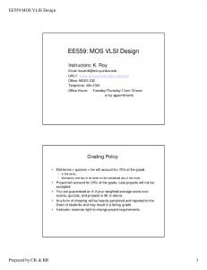
VLSI Synthesis VLSI süntees IAY0050 - 2.5 AP 3 2-1-0 E K
http://mini.li.ttu.ee/~lrv/IAY0050/
Peeter Ellervee IT226
620 2258
511 3631
http://www.ttu.ee/users/lrv/
[email protected]
http://mini.li.ttu.ee/~lrv/
vlsi - introduction - 1
© Peeter Ellervee
D e p a r t m e n t
o f
C o m p u t e r
E n g i n e e r i n g
Course plan • • • • • • • • • • • •
Introduction [2h]
•
Hands-on exercises [4*4h]
Synthesizable VHDL [2h] Synthesizable Verilog [2h] Design methodology [2h] Physical level synthesis [2h] Logic level and register-transfer level syntheses [2h] High-level synthesis [2h] Scheduling in high-level synthesis. [3h] Allocation and binding in high-level synthesis. [3h] Local timing transformations [2h] System level synthesis [2h] Code transformations at system level [4h]
•
© Peeter Ellervee
Introduction. Elevator controller. Filter Design
vlsi - introduction - 2
D e p a r t m e n t
o f
C o m p u t e r
E n g i n e e r i n g
Textbooks •
John F. Wakerly, “Digital Design: Principles and Practices.” Pearson/Prentice Hall, 2006
•
Dirk Jansen et al. (editors), “The electronic design automation handbook.” Kluwer Academic Publishers, 2003
• •
M. Morris Mano, “Digital Design.” Prentice-Hall, 2002
• •
Daniel D. Gajski, “Principles of Digital Design.” Prentice-Hall International Inc., 1997.
K.C. Chang, “Digital systems design with VHDL and synthesis: an integrated approach.” IEEE Computer Society, 1999 Michael John Sebastian Smith, “Application-Specific Integrated Circuits.” AddisonWesley Pub Co, 1997. •
http://www.edacafe.com/books/ASIC/ASICs.php
•
Douglas J. Smith, “HDL chip design: A practical guide for designing, synthesizing and simulating ASICs and FPGAs using VHDL or Verilog.” 1997.
•
Giovanni De Micheli, “Synthesis and Optimization of Digital Circuits,” McGraw-Hill, 1994.
vlsi - introduction - 3
© Peeter Ellervee
D e p a r t m e n t
o f
C o m p u t e r
E n g i n e e r i n g
Motivation •
System-on-Chip (SoC) requires new design methodologies • •
to increase designers productivity to get products faster into market
•
There exists a demand for efficient design methodologies at higher abstraction levels
•
A different thinking needed from the designers
•
At higher abstraction levels • •
a designer has much wider selection of possible decisions each of these decisions has also a stronger impact onto the quality of the final design
© Peeter Ellervee
vlsi - introduction - 4
D e p a r t m e n t
o f
C o m p u t e r
E n g i n e e r i n g
Optimizations •
Optimizations at logic level • •
thousands of nodes (gates) can exist
•
optimization algorithms can take into account only few of the neighbors
•
only few possible ways exist how to map an abstract gate onto physical gate from target library
Optimizations at register transfer level (RTL) • •
•
handle hundreds of nodes exist (adders, registers, etc.) there are tens of possibilities how to implement a single module
At higher levels, e.g. at system level • • •
there are only tens of nodes to handle (to optimize) there may exist hundreds of ways how to implement a single node every possible decision affects much stronger the constraints put onto neighboring nodes thus significantly affecting the quality of the whole design
vlsi - introduction - 5
© Peeter Ellervee
D e p a r t m e n t
o f
C o m p u t e r
E n g i n e e r i n g
Decisions at higher abstraction levels •
Two major groups of decisions •
selection of the right algorithm to solve a subtask •
making transformations inside the algorithm, e.g. parallel versus sequential execution
•
affect primarily the final architecture of the chip
•
decisions about the data representation •
e.g. floating point versus fixed point arithmetic, bit-width, precision.
•
Selection of a certain algorithm puts additional constraints also onto the data representation
•
Selecting a data representation narrows also the number of algorithms available
© Peeter Ellervee
vlsi - introduction - 6
D e p a r t m e n t
o f
C o m p u t e r
E n g i n e e r i n g
Abstraction levels
message: header1 & payload1 | header2 & payload2 | header3 & payload1 | illegal
0F
•
AB
0234
34
2FE4
14DA
System level • •
modules / methods channels / protocols
. . . message=receive(channel_1); add(list,message); sort(list); send(first(list,REMOVE),channel_2); . . .
vlsi - introduction - 7
© Peeter Ellervee
D e p a r t m e n t
o f
C o m p u t e r
Abstraction levels
message: 0001 & xxxxxxxxxxxx | 0010 & yyyyyyyyyyyy | 0101 & xxxxxxxxxxxx | ----------------
0F
•
E n g i n e e r i n g
AB
34
0234
2FE4
14DA
Algorithmic level • •
(sub)modules / algorithms buses / protocols
. . . message=blocking_receive(channel_1); append(list,message); bubble_sort(list); msg_pnt=first(list); message= *msg_pnt; nonblocking_send(message,channel_2); remove(list,msg_pnt); . . .
© Peeter Ellervee
vlsi - introduction - 8
D e p a r t m e n t
o f
C o m p u t e r
E n g i n e e r i n g
Abstraction levels +
•
Register transfer (RT) level • •
•
>
blocks / logic expressions
&
buses / words
Logic level • •
logic gates / logic expressions nets / bits
vlsi - introduction - 9
© Peeter Ellervee
D e p a r t m e n t
o f
C o m p u t e r
Abstraction levels
•
Physical level
•
transistors / wires
•
polygons
© Peeter Ellervee
vlsi - introduction - 10
E n g i n e e r i n g
D e p a r t m e n t
o f
C o m p u t e r
E n g i n e e r i n g
HW design flow
Design flow •
System level
Specification refinement • •
•
from higher to lower abstraction levels refinement = transformations
Algorithmic level
Algorithm selection • •
•
RT level
universal vs. specific speed vs. memory consumption
Logic level
Partitioning •
•
introducing structure
Physical level
Technology mapping •
replacing Boolean equations with gates
vlsi - introduction - 11
© Peeter Ellervee
D e p a r t m e n t
o f
C o m p u t e r
E n g i n e e r i n g
Y-chart System level Algorithmic level
Behavioural Domain
Register transfer level
Structural Domain
System Specification CPU, Memory Logic level Algorithm Processor, Sub-system Register-transfer specification ALU, Register, MUX Circuit level Boolean Equation Gate, Flip-flop Transistor Differential Equation Rectangle / Polygon-Group Standard-Cell / Sub-cell Macro-cell Block / Chip Chip / Board
Physical Domain © Peeter Ellervee
vlsi - introduction - 12
D e p a r t m e n t
o f
C o m p u t e r
E n g i n e e r i n g
Y-transformations Synthesis Analysis
Behavioural Domain
Re fi Ab stra
Structural Domain
nem ent
ctio n
Generation
Optimization
Extraction
Physical Domain (Geometrical Domain)
vlsi - introduction - 13
© Peeter Ellervee
D e p a r t m e n t
o f
C o m p u t e r
E n g i n e e r i n g
Design steps •
System design a.k.a. Architectural-level synthesis a.k.a. High-level synthesis a.k.a. Structural synthesis • •
•
description / specification --> block diagram determining the macroscopic structure, i.e., interconnection of the main modules (blocks) and their functionality
Logic design • •
•
block diagram --> logic gates determining the microscopic structure, i.e., interconnection of logic gates
Physical design a.k.a. Geometrical-level synthesis •
logic gates --> transistors, wires
© Peeter Ellervee
vlsi - introduction - 14
D e p a r t m e n t
o f
C o m p u t e r
E n g i n e e r i n g
Synthesis -- levels and tasks •
System Level Synthesis •
•
Clustering. Communication synthesis.
High-Level Synthesis • •
•
Resource or time constrained scheduling Resource allocation. Binding
Register-Transfer Level Synthesis •
•
Data-path synthesis. Controller synthesis
Logic Level Synthesis •
•
Logic minimization. Optimization, overhead removal
Physical Level Synthesis •
Library mapping. Placement. Routing
vlsi - introduction - 15
© Peeter Ellervee
D e p a r t m e n t
o f
C o m p u t e r
E n g i n e e r i n g
Synthesis -- design automatization transistors per chip
technological capability
designer’s productivity
today
© Peeter Ellervee
vlsi - introduction - 16
time
D e p a r t m e n t
o f
C o m p u t e r
E n g i n e e r i n g
Design automation •
1990 -- 4 Kgates / year / designer
•
1993 -- inhouse place and route -- 5.6K
•
1995 -- engineer (RTL-->GDSII) -- 9.1K
•
1997 -- small blocks reuse (2.5K-75K) -- 40K
•
1999 -- large blocks reuse (75K-1M) -- 56K
•
2001 -- synthesis (RTL-->GDSII) -- 91K
•
2003 -- intelligent test-bench -- 125K
•
2005 -- behavioral and architectural levels, HW/SW (co)design -- 200K
•
2007 -- very large blocks reuse (>1M, IP cores) -- 600K
vlsi - introduction - 17
© Peeter Ellervee
D e p a r t m e n t
o f
C o m p u t e r
E n g i n e e r i n g
Market = $$$ •
•
•
•
Design cost •
design time & chips production cost
•
huge investments (G$)
•
almost impossible to correct
High cost of modifications •
large production volumes are more cost effective
•
zero-defect is very important
•
following market trends is important
Price is inversely proportional to production volume •
common purpose processors - cheap but not always usable
•
ASIC - application specific tuning (e.g. telecommunication)
•
prototypes - flexibility is extremely important in the development phase
•
special purpose chips (e.g. satellites)
Reconfigurability •
© Peeter Ellervee
flexible products, possibility to modify working circuits
vlsi - introduction - 18
D e p a r t m e n t
o f
C o m p u t e r
E n g i n e e r i n g
Design criteria •
Three dimensions - area, delay, power • •
•
size, speed, energy consumption four dimensions - plus testability (reliability)
Area •
•
gates, wires, buses, etc.
Delay •
•
inside a module, between modules, etc.
Power consumption •
•
average, peak and total
Optimizations • •
transferring from one dimension to another design quality is measured by combined parameters, e.g., energy consumption per input sample vlsi - introduction - 19
© Peeter Ellervee
D e p a r t m e n t
o f
C o m p u t e r
E n g i n e e r i n g
HDL - designing Systems-on-a-Chip (SoC)
Idea
Language
!!!
Technology
TTL VHDL Verilog Matlab
CMOS GaAs whatever
© Peeter Ellervee
vlsi - introduction - 20
Chip
D e p a r t m e n t
o f
C o m p u t e r
E n g i n e e r i n g
Communication models •
Shared memory • •
•
Persistent medium - memory, value retains until overwritten. Non-persistent medium - buses.
Message passing: channel & send/receive • • • •
•
uni-directional; bi-directional point-to-point; multi-way blocking; non-blocking buffered; non-buffered
Synchronization •
asynchronous - self-timed •
•
extra signals needed
synchronous •
global clock required
vlsi - introduction - 21
© Peeter Ellervee
D e p a r t m e n t
o f
C o m p u t e r
E n g i n e e r i n g
Asynchronous communication •
Data exchange between modules running at different clocks
•
Data exchange between self-timed modules
•
Metastability problem - architecture in which the circuits are employed in
req_in
S
R
R
req_out
ack_out
ack_in
© Peeter Ellervee
S
vlsi - introduction - 22
D e p a r t m e n t
o f
C o m p u t e r
E n g i n e e r i n g
Synchronous communication •
Data exchange between modules running at the same clock
•
Data exchange at certain moments only
•
Clock distribution problem • •
clock skew - differences in wire lengths clock trees are power hungry
vlsi - introduction - 23
© Peeter Ellervee
D e p a r t m e n t
o f
C o m p u t e r
E n g i n e e r i n g
Communication environment •
Channels • •
•
physical vs. virtual buffered vs. non-buffered
Shared memory • •
•
multi-port memories vs. global bus arbitration needed
Buses • • •
non-persistent medium synchronous vs. asynchronous buses broadcasting vs. point-to-point
© Peeter Ellervee
vlsi - introduction - 24
D e p a r t m e n t
o f
C o m p u t e r
E n g i n e e r i n g
Embedded Systems more than can openers and microwave ovens ....
•
Microprocessor Unit Sales, 1999 (32-bit only, all markets)
94% (5 billion chips) of the world market is embedded microprocessors vs. 6% PC/ws! Processors for PC’s, workstations and servers get all the attention, but embedded microprocessors make the world go “round”
•
Old microprocessors rarely die, and they hardly ever fade away - they just become embedded
•
64 bits processors now follow the same trend
others worldwide volume (millions)
•
400
300
200
x86 SuperH
MIPS 680x0
100 ARM 0
embedded
workstations
Mac PC computer
vlsi - introduction - 25
© Peeter Ellervee
D e p a r t m e n t
o f
C o m p u t e r
E n g i n e e r i n g
Reality •
Found On First Spin ICs/ASICs •
Functional Logic Error -
•
Analog Tuning Issue -
20%
•
Signal Integrity Issue -
17%
•
Clock Scheme Error -
14%
•
Reliability Issue -
12%
•
Mixed Signal Problem -
11%
•
Uses Too Much Power -
11%
•
Has Path(s) Too Slow -
10%
•
Has Path(s) Too Fast -
10%
•
IR Drop Issues -
7%
•
Firmware Error -
4%
•
Other Problem -
3%
•
43%
Overall 61% of New ICs/ASICs Require At Least One Re-Spin. •
© Peeter Ellervee
Aart de Geus, Chairman & CEO of Synopsys, Boston SNUG keynote address, 9.09.2003
vlsi - introduction - 26
D e p a r t m e n t
o f
C o m p u t e r
E n g i n e e r i n g
Future? 2000
2010
2 Gbit
memory size
256 Gbit
8⋅106
transistors per cm2
160⋅106
1.5 GHz
internal clock frequency
10 GHz
0.5 GHz
external / bus clock frequency
1.5 GHz
2000
pin count
6000
800 mm2
chip area
1300 mm2
140 nm
wire width
40 nm
1.5 V
supply voltage
0.6 V
100 W
power consumption
170 W
0.5 W
power consumption (batteries)
1.5 W
vlsi - introduction - 27
© Peeter Ellervee
D e p a r t m e n t
o f
C o m p u t e r
E n g i n e e r i n g
Problems
physical level
quantum effects noise
logic level
crosstalk speed of light
system level
# of transistors
10 mm --> (108 m/s) --> 10-10 s --> (10%) --> 1 GHz !?
•
GALS - globally asynchronous locally synchronous
•
mixed signal - digital and analog circuits on the same chip
© Peeter Ellervee
vlsi - introduction - 28