International Journal of Automation and Computing
04(1), January 2007, 100-106 DOI: 10.1007/s10453-004-5872-7
A Concept of Dynamically Reconfigurable Real-Time Vision System for Autonomous Mobile Robotics. Aymeric DE CABROL1,∗ 1
Thibault GARCIA2
Patrick BONNIN1,3
Maryline CHETTO2
L2TI, Universit´ e Paris 13, 99 avenue JB Cl´ ement, 93 430 Villetaneuse, FRANCE 2 IRCCyN, 1 rue de la No¨ e, BP 92 101, 44 321 Nantes CEDEX 03, FRANCE 3
LRV, 10–12 Avenue de l’Europe, 78 140 V´ elizy, FRANCE
Abstract: In this article, we describe specific constraints of vision systems that are dedicated to be embedded in mobile robots. If PC based hardware architecture is convenient in this field because of its versatility, its flexibility, its performance and its cost, current real-time operating systems are not completely adapted to long processings with varying duration, and it is often necessary to oversize the system to guarantee fail-safe functioning. Also, interactions with other robotic tasks having more priority are difficult to handle. To answer this problem, we have developed a dynamically reconfigurable vision processing system, based on the innovative features of Cl´ eopatre real-time applicative layer concerning scheduling and fault tolerance. This framework allows to define emergency and optional tasks to ensure a minimal quality of service for the other subsystems of the robot, while allowing to adapt dynamically vision processing chain to an exceptional overlasting vision process or processor overload. Thus it allows a better cohabitation of several subsystems in a single hardware, and to develop less expensive but safe systems, as they will be designed for the regular case and not rare exceptional ones. At last, it brings a new way to think and develop vision systems, with pairs of complementary operators. Keywords:
1
Real-Time Vision, Dynamic Reconfiguration, Embedded Systems, Robustness, Real-Time Operating System.
Introduction.
Mobile Robotics usually requires a vision system because the sight is a very convenient means to detect and recognize from afar things with unexpected or badly defined appearance. However, extracting relevant information from the video stream is a very complex process, requiring a significant amount of computing power. Moreover, an erroneous result will cause a wrong action from the robot, which may be dangerous as well as for the machine itself, as for its environment where might be human beings. Therefore design of the vision system must be thought carefully to match specific requirements and constraints of the robot and its mission. Some mobile robotic systems are remotely controlled, and their vision system only acquires a video stream sent to the remote human pilot. This solution is efficient for short-range missions in visually complex or unexpected environments, where analysis and decision skills of the mind are required because the ability of the computer is either insufficient or unreliable. This is used for robots dealing with emergency situations in nuclear plants, as Cybernetix’s BROKK and SAMM [1] . When the processing of the video stream can be achieved by a computer, two strategies exist. If the required dimensions of the mobile robot prohibit the embedding of the vision processing system, this one can be set as a distant static processing center, remotely linked to the mobile robots. Either these each have a camera, and send data to the processing center to get back useful information (eg. position of a target after a heavy 3D incremental reconstruction of the environment from images sent by several robots), or the processing center may have its own vision system and guide some blind mobile robots (eg. RoboCup 2007.02.26; 2007.07.17 This work is supported by the French research office, grant number ´ 01 K 0742, under the name of CLEOPATRE project. *Corresponding author. E-mail address:
[email protected]
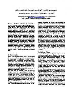
Small-Size League [2, 3] ). Nevertheless, this strategy cannot be used when the application has hard constraints of video latency (as for martian rovers [4] ), cadence and regularity of process (systems with visual servo control as in [5] ). To reach a high level of autonomy, the vision system must be embedded within the mobile robot. As technology evolves and matures, robotic applications become more various, and robots much more complex. Because of interactions with other mechanical parts of the robot, servo controls, and a varying unsettled environment, it is mandatory to use a real-time vision system, which can be defined as a vision system for which the processing meets cadence and latency constraints due to client systems, environment, and the robot itself (Fig. 1). Such systems can be designed using three different families of hardware: electronic, programmable electronic or computer architecture. The fully electronic hardware, because of its lack of flexibility and its cost and duration of development, is more and more replaced in industrial world by the programmable electronic. But the flexibility of this latter is still inferior to those of the computer based architecture, as over the past few years progress have been made in processing power and speed, integration (eg. small size of PC-104 boards for embedded applications), diversity and cost of peripherals (cameras, sensors, communications), and performance and reliability of Real-Time Operating Systems. As computer based architecture offers a flexibility of design, an easiness of conception and modification, and open-source community knowledge source and tools for a low cost, it has become one of the most interesting hardware for robotics. But the Vision has specific features and constraints that are difficult to deal with yet. These will be detailed in the next section of this article. As current Real-Time Operating System design does not fit completely these particular requirements, the LINA laboratory1 has developed a library 1
Computer Science Laboratory, the leader of Cl´ eopatre project.
2
International Journal of Automation and Computing 04(1), January 2007
time constant
time constant
of the robot
of the environment video cadence
Real−Time Vision System
cadence of input data
maximal latency for results
client subsystems asking for information Figure 1 Definition of a Real-Time Vision System.
of Real-Time software components within the French National R&D project named Cl´eopatre. These innovative features, which are very interesting and promising for Vision Processing, are shown and explained in Section 3. In Section 4, we describe the system we have implemented. As we focus on the difficulty to match a robust vision processing with a limited robotic hardware, the robotic system we describe uses only vision sensors. Finally we will present in Section 5 how such a system allow to design and realize a Dynamically Reconfigurable Vision System, able to adapt itself to fit instantaneous available computing power in embedded systems where Vision has a low priority, and thus to ensure the robustness to scheduling faults.
2
Applicative constraints.
Vision systems that are embedded in an autonomous mobile robotic systems evidently have to fulfill the requirements specific to the purpose of the machine. But several constraints are common for embedded robotic vision systems, so they are to be detailed thereafter. They follow from our experience in mobile robotics, for legged robots (the RoboCup’s 4-legs league [6, 7] ), a wheeled robotic conveyor for industry (Cl´eopatre RNTL project, [8, 9, 10, 11] ), and now the RoboCup Rescue challenge [12] , where robots have to complete rescue missions after a disaster, so in a very uncooperative environment.
2.1
Inner constraints of a vision system.
An embedded robotic vision system must meet four criteria: • It must see far in order that the robot can detect the elements of the scene soon enough to be able to anticipate. This criterion depends on the technical features of the video device: its resolution, its depth of focus, etc.
• It must be fast compared with the dynamics of the observed scene, so that high-level results of the vision system are not obsolete. If the process is too slow, the results will be useless because of the difference between the observed past scene and the present one. This situation may even provoke a pumping, and endanger the stability of the whole system. This swiftness is expressed by two parameters: the latency, which is the delay between frame grabbing and results sending, and the cadence, the number of frames processed each seconds. Usually, the latency must be low and the cadence must be sufficiently high. • It must be reliable, as the results of vision processing will make the robot react. In order to avoid aberrant behavior and to reach high performance, the vision system must be designed to ensure a high detection rate, a low false alarm rate, and an optimal quality of processing. • At last, it must be robust to continue to be reliable despite variations of the environment. Most vision processing algorithms require parameters to fit the external conditions (ambient luminosity, range of speed for targets, etc.), the internal conditions (angle and speed of joints of the robots, odometry, etc.), and the elements of the scene (list of colors to recognize, shapes to segment etc.). As reliability cannot be guaranteed outside of the validity range, either must this range be as vast as possible, or parameters must be adapted periodically to fit the observed variations in the environment. Though it must be kept in mind that the vision system is embedded within the whole robot, and consequently it must coexist with all other subsystems. Hence the following constraints: • As it is embedded, the vision system must run with mere available computing resources. As vision processing is usually computing power consuming, it may be impossible to embed the vision system without increasing the computation power of the target, which can be done by adding a processor dedicated to vision or a specific processing board. Still, as embedded systems are designed to be the smallest and the most economic they can be, adding a component will increase volume of the machine, its electrical consumption, the duration of its realization, and consequently the cost of the project. Therefore, extensions must be restricted to the strictly necessary and be carefully thought. • Also, as it is a mere sensor, the vision system must give a service to the other subsystems, and it has a lower priority than more critical parts (eg. Control/Command, which process cannot be delayed without making the robot unstable). • The third constraint follows from the two previous ones taken into account simultaneously: the vision system must not jam the whole system, whatever the reason. For example, such a jamming would keep Con-
de Cabrol et al./ Dynamically Reconfigurable Real-Time Vision System for Autonomous Mobile Robotics.
trol/Command from running correctly, making the behavior of the robot unpredictable and dangerous for its environment, in which human beings can be. All these considerations must be kept in mind when a vision system is designed. Meanwhile, any project has economic constraints, and the designer has either to choose the smallest hardware to run the planned vision system, or to select the most efficient algorithms for a specific hardware.
2.2
Mission constraints.
In our mobile robotics applications, whether the environment is under control (RoboCup 4-legged league, industrial conveyor) or not (RoboCup Rescue), the vision system is in charge of several tasks of target localization and environment modeling. The subsystems of the robot have various needs. The Piloting servo control loop and the Path Planning module need obstacles detection and localization, so that to be able respectively to stop before the collision or to compute a new safe trajectory; the Navigation module needs to know the position of the robot, and may have to map the environment to determine the next place to reach. All this information can be given by the Vision system. For the robotic conveyor developed during the Cl´eopatre project or for the RoboCup 4-legged league, the robot manœuvers indoors, in a environment which some properties are known and that can be made cooperative. Thus, provided that the ground has a known and rare color, an obstacle detection can be done from a color region segmentation: then, the color regions detected in the ground area are potential obstacles, which position can be computed from their coordinates in the image. Also, the localization of the robot can be done visually from the detection and the localization of known objects in the reference of the robot. This method requires that the known objects are unambiguous and at precisely known locations, and that they are numerous enough to be usable. A convenient solution is to use cylindrical landmarks, with colored strips, as it has been used in the RoboCup. The cylindrical shape makes landmarks appear the same from all around on the floor, and the sequence of colors used for the strips makes them unique. So, a color region detection followed by an analysis of connected regions and a triangulation leads theoretically to the localization of the robot. But application teaches that usually not enough landmarks are visible at the same time to perform a regular triangulation; consequently, a solution proposed by Hugel & al. [7] consists in computing a triangulation whenever it is possible, or else use a particle filter to find the most probable location corresponding to current view. At last, to map the environment, the vision system may use an incremental 3D reconstruction, based on a color edge detection. However the durations of all vision processes must be managed conscientiously as some vision processes will be too slow to be usable by the rest of the robot. As an example, for a mobile robotics application, as well the Navigation and the low level servo control loops need to know the position, but standard vision-based localization algorithms are too slow to be used directly by the low level servo control,
3
which usually runs at least at 1 kHz. That is why the position is usually given by proprioceptive sensors (odometer, accelerometer, etc.), and is periodically corrected by the vision-extracted position, as those measurements diverge quickly. Also some theoretical solutions may be found too slow in practice; it was the case of using a color region segmentation in the real-time vision system. Then, either another family of process must be used, even if this does not fit the problem as well (eg. Edge Segmentation), or a more efficient algorithm must be designed (as our fast color region segmentation, exposed in [13] ). That is why, in a real-time vision system, the cadences of processes must be chosen carefully to fit the periods of all client subsystems that need extracted information. To illustrate this, Fig. 2 shows that there is a symmetry between the vision tasks and the client control loops, so the vision processes used by the Pilotage loop must be fast enough to deliver information that is not obsolete, whereas those required by the Navigation loop can be a little bit slower, as this control loop has a smaller frequency.
high−level process (localization) low−level process (obstacle detection) Vision System
Mobile System pilotage servo loop
navigation servo loop
Figure 2 Symmetry of cadences in a robotic vision system.
2.3
Selected hardware.
Nowadays, a mobile robot may be realized using any of the three standard hardware architecture: electronics, programmable electronics and PC-based software implementation. For our research & development approach, the whole electronics realization is not flexible enough. And, even if the programmable electronics has made progress over the past few years, the PC-based architecture is still less expensive and more versatile, and has a great calculation capacity. Moreover, the recent developments and advances of realtime operating systems lead to current wide offer of systems and tools. Those based on Linux, as DIAPM RTAI [14] , are particularly interesting because of their high-level of performance and their permanent improvement by their community, and because they can be embedded on very limited targets by using a minimal Linux kernel. The fact that some of them are free and open-source is an additional asset for research purpose.
4
2.4
International Journal of Automation and Computing 04(1), January 2007
Compromise between safety and cost.
To fit the temporal constraints and to enable an efficient exchange of information with other subsystems of the robot, the vision processes are implemented as real-time tasks. The Vision Processing has still several particularities that make these tasks different from other one. First of all, a vision process lasts generally much longer than most processes of other subsystems. This is due to the fact that processed data is an image, which size is 19, 2 kilobytes for a greyscale low-resolution QSIF (160 × 120 pixels, with 1 byte per pixel) or 57, 6 kB for a color one. The lowlevel vision processes test and use all these bytes to extract some higher level data, and this must be done at video rate (25 Hz). This requires a large amount of the embedded computing power. The second point is that the duration of a vision process often depends on the content of the scene: an Edge Points Chaining process will have more things to do in an image containing many outlines than on an empty image. Besides this, it may be difficult to determine the worst case, and this one can be very rare. As the vision system has the same importance as a sensor and must not provoke a scheduling fault because one of its tasks has an exceptionally long duration, the design of the real-time vision system must ensure a safe functioning of the whole robotic system. With existing real-time operating systems, this usually implies the choice of the period of the task exceeding its worst expected duration. Consequently the system is oversized for normal situations, and this means further expenses and less efficiency. So our researches have focused on obtaining a fail-safe vision system with a limited hardware, considering economic constraint.
2.5
Toward a dynamically reconfigurable vision system.
A means to reach this goal is to be able to handle independently usual situations and exceptional ones, due to either the vision system itself or interaction with the other subsystems of the robot. To prevent any too long duration, the vision system would be designed to modify the unfolding of processes or their content so as to respect the schedule. But most of the time the dynamic reconfiguration of a vision system is a topic distant from these considerations. Many researches have been conducted to develop a dynamic reconfiguration of vision systems on programmable electronic hardware, as for ARDOISE project [15, 16] . As the programmable electronic components are expensive but very fast, this topic aims to load successively several steps of a algorithm into FPGA during one period, in order to do this operation on a component too small to contain the whole process [17, 18, 19] . In other cases, the dynamic reconfiguration consist in modifying the sequence of process in Incremental Processing Systems [20, 21, 22] or to choose operators to apply on several areas of the image for the Blind-Processing Systems of image restoring [23, 24] . One of the rare studies concerning the dynamic reconfiguration of the processing chain to adapt a vision system to the hardware is [25] , where the system searches the moving
objects in the image and defines their bounding boxes, then select which boxes to process from the expected duration of the process knowing the dimensions of each box. But, if this kind of approach can be interesting for a standalone image processing system, this cannot work if other systems share the same processor, as in robotics. Therefore, a reconfiguration system, which enables to adapt vision system to instant available computing power, must run at a higher hierarchical level than the Vision System. Seeing that no operating system allowed this in year 2001 as far as we know, LINA laboratory studied then the feasibility of such an OS and developed the Cl´eopatre real time applicative layer. Then we have tried to make good use of the innovative features it offered, so as to design a robust dynamically reconfigurable vision system.
3
Cl´ eopatre Real-Time Operating System facilities.
Cl´eopatre is a real-time applicative layer adding new tools and services to regular real-time operating systems, which corresponds to current needs of developers. It has been developed as the core element of the French National R&D project Cl´eopatre, and it aims to provide LGPL opensource software components for robotics industrial applications. This section will glimpse its original features, and then detail the two main mechanisms that are of the utmost interest for embedded robotic vision systems.
3.1
Overview.
Cl´eopatre is a real-time applicative layer that can be appended to regular real-time operating system to give them new abilities. This is implemented owing to an OS abstraction layer named TCL (for Task Control Layer ) that is the only element that has to be adapted to the targeted RTOS2 (as shown in Fig. 3). Then Cl´eopatre specific tasks can be run together with the regular RTOS tasks and user space processes. At present time, this has been used successfully with RTAI and RT-Linux. Cleopatre tasks CLEOPATRE
RTAI tasks
Linux processes
RTAI
Operating System Abstraction Layer of Cléopatre : TCL
Linux
Hardware Abstraction Layer of RTAI
Hardware
Figure 3 Software layers using Cl´ eopatre, with RTAI.
The innovative components of Cl´eopatre can be sorted in four fields: scheduling, aperiodic tasks servicing, synchronization and fault tolerance [26] . All these components has 2
Acronym for Real Time Operating System.
5
de Cabrol et al./ Dynamically Reconfigurable Real-Time Vision System for Autonomous Mobile Robotics.
3.2
Deadline Mechanism.
The Deadline Mechanism enables the designer to associate an emergency tasks to each regular one, in order to ensure a minimal functioning of the system in any situation. More often than not, real time systems runs periodic tasks, that contains one operator or more in the case of the vision system. The duration of each task must be less than the critical delay defined by the designer, that can be used by the scheduler to define priority of this task. If the task outlast this duration, a scheduling fault occurs and may have several consequences: results of the process may be obsolete, be unserviceable for client subsystems, and provoke either a transient bad behavior or a complete breakdown of the robot. Therefore this kind of problem must be avoided. In order to do so, Deadline Mechanism enables to assign two tasks for a single operation, for which critical delay has been defined. First task ensures normal functioning of the system, and the second one is run only if the first one outlasts its deadline (Fig. 4). Logically, the duration of the emergency task is shorter than the first one’s, and the quality of its results are worse: its purpose is to guarantee
a degraded functioning to the system. When this mechanism is activated, the scheduler places at first all emergency tasks using the Earliest Deadline as Late as possible algorithm (EDL), that sets their activation date as late as possible according to their maximal duration (which must be known) and the deadline of corresponding operation. Then the principal tasks will be placed into the remaining spare time, owing to another scheduling algorithm that is chosen by the designer. If the principal task has completed before the beginning of the emergency task, this latter one is aborted, and the scheduling is computed again to use freed time. If it has not, the exceptional duration of the principal task has no lethal result for the whole system because an emergency behavior planned during the design phase is run.
dA1
dB 11111 00000 00000 11111
00000 00000 11111 A2 A11111 B 2 00000 11111
A′1
A1
00000 11111 00000 11111
dA2 A′2
A2 is aborted
Figure 4 DM : example of use. A′ is backup task of task A. During the first period, principal function has completed successfully, so A′1 is abandoned. During the second period, an aperiodic task B is running with more priority, so A is delayed. As A cannot complete before the activation of A′2 , A is aborted and A′2 is activated.
3.3
Imprecise Computation.
In order to take advantage of the free time remaining after all normal tasks have been run, Cl´eopatre has another mechanism called Imprecise Computation (IC), which enables to run extra tasks when processor is underloaded. The purpose of this mechanism is to enable to design some optional tasks to refine the results of a principal task, among other things. The scheduler runs this optional task during free time after the completion of the main task it refines. If the optional task has not completed before its deadline, it is merely aborted (Fig. 5). An optional task itself can also possess another optional refining task.
dA1 A1
B1
dB1 11 00 00 11 00 11 00 11 00 11 00 11 00 11
A1+
been implemented as kernel modules, so they can be loaded on demand to fit only the needs of a specific application. This flexibility ensures the lowest footprint. Most existing RTOS offers only a static scheduling, which does not fit with several families of application, especially Robotics. Consequently Cl´eopatre takes advantage of recent studies in scheduling theory and offers both static and dynamic schedulers. With a static scheduler like Deadline Monotonic [27] , priority is defined once for all for all periodic tasks, the ones with the shortest deadline being granted with the highest priority. This mechanism does not allow to change the tasks periodicity during the running of the application, which may be required in robotics to adapt the processes to a modification of external environment. But the dynamic priority scheduler Earliest Deadline First [28] of Cl´eopatre allows these changes, as the task with earliest deadline will be executed first. Three aperiodic tasks servers are also provided to schedule the soft and hard aperiodic tasks together with the periodic ones: BG (Background Server ), EDL (Earliest Deadline as Late as possible) [29] and TBS (Total Bandwidth Server ) [30] . The two latter ones are optimal in the sense that they minimize the mean response time for the soft aperiodic tasks, and they maximize the acceptance ratio for the hard aperiodic tasks. They also guarantee that these aperiodic tasks meet their timing requirements. The synchronization components are three sets of semaphores that can be used with any scheduler (static and dynamic ones) and prevent deadlocks and priority inversion situations. These mechanisms are the Super-Priority Protocol (SPP), the Priority Inheritance Protocol (PIP) [31] and the Priority Ceiling Protocol (PCP) [32] , that offer various compromise between security and overhead. At last, Deadline Mechanism (DM) [33] and Imprecise Computation (IC) [34] are two features that allow to implement fault tolerant systems able to manage a transient overload. As they are of the utmost interest for the vision processing, they are presented in detail in the two next paragraphs.
A2
giving up A1 +
dA2 B2
dB2 A2+
A3
dA2+
Figure 5 IC : example of use. A and B are two principal periodic tasks, with dAi and dBi being the deadlines of Ai and Bi . A+ is the optimal task of A. During the first period, A+ cannot complete before next activation of A, so it is aborted. During second period, B is shorter so A+ can run until completion.
6
4
International Journal of Automation and Computing 04(1), January 2007
Dynamically Reconfigurable Vision System.
Classic vision systems compel to choose the best algorithm for each operator. The best algorithm means the one with the best compromise for the targeted mission, and appraisal criteria are if the algorithms meets mission needs, the required quality of results, their preciseness, the speed of the process and its robustness to several parameters of the robot or its environment. But a compromise always means that the chosen algorithm has mean performances, and that a better one could be found for each criterion. Moreover, a safe implementation impose to consider the worst situations to determine the periodicity of tasks, even if they are extremely rare: this makes the system oversized, and has repercussion on its cost. Therefore the fault tolerance mechanisms of Cl´eopatre are interesting as they enable to implement a dynamic reconfiguration of the tasks sequence according to the state of the whole processor and not only the vision subsystem, and to guarantee a fail-safe behavior. Moreover, as it is possible to run two different tasks to do a single operation, principal task will use the best algorithm for standard situations, and emergency task will implement a faster algorithm for which maximal duration is known.
4.1
Nominal and backup systems.
Task 1 on CPU 1 Task 3 on CPU 1
Task 2 on CPU 1
Results
grabbing
Right frame
Results
Left frame grabbing
To illustrate this, we have implemented with these mechanisms a Color Region Segmentation for a robotic system. The most robust algorithm is a classic region segmentation, that operates a region growth simultaneously on the three color planes. It does not need a priori knowledge, and its only parameters are the criteria of homogeneity for monochromatic intensities. Consequently, it is quite insensitive to lighting variations, one of the biggest problem in robotic vision. But this process is relatively long, and its duration fluctuates according to the number and the size of color regions in the image, even if this still fits the cadence and latency constraints of the system. Another way to segment color regions of an image is to do a Color Classification followed by a Connected Components Decomposition. The Color Classification requires several parameters to divide the color space (RGB, BGR, YUV, etc.) to do a low level merging of the information in the three spectral planes, similarly to low-level merging presented in [35] and [36] . Then, the Connected Components Decomposition can be done by Rosenfeld & Pfaltz’s algorithm [37] or by a run-length decomposition [38] , and it requires only two scans of the classified image. So this algorithm is faster than the Region Growth and its duration more regular: so an estimate of its maximal processing time can easily be defined. Nevertheless these operators are efficient only if parameters of the Color Classification truly fit the current situation, but apparent color of objects usually depends on the ambient luminosity and the type of surface of the object (eg. there may be some specular spots). That’s why the Color Classification parameters are often chosen by a human expert by hand, or with a semiautomatic process. Another means to find these parameters
is to compute them automatically from the observation of an element with known colors, as a color test card embedded on the robot [4] , or by a recognition of some elements of the scene (cf. Vision Challenge of RoboCup’05). To be able to use the Deadline Mechanism of Cl´eopatre, the candidate algorithms must be sorted. The one that fits the best mission constraints will be used for principal task, and the one with a known maximal duration will be used for emergency task. In this example, the Color Region Segmentation is robust enough to be used for the main task, and the other will be for the emergency one. Even if the results of the latter are not as robust as the other one’s, this algorithm will be able to give a result before the deadline, which is mandatory for the other subsystems to run properly, and will prevent jamming. The method to define optional tasks is wholly different. They ca, be either refining operators for main operators, or totally different and independent processes. Using the fault tolerance mechanisms of Cl´eopatre, the splitting of the processing chains into real-time tasks has to be done a different way than usual. In a classic real-time vision system, one task generally gathers a linear sequence of operators, each of them depending only on the results of the previous one (Fig. 6). When several process have to run simultaneously and use the same input data, they can be run on different processors. But if faults tolerance mechanisms of Cl´eopatre are used, there are numerous possible sequence of operators, due to the fact that dynamic reconfiguration substitutes some emergency operators to regular ones and possibly schedules also some optional tasks. If only the Deadline Mechanism is used, the tasks splitting must create a task for each linear sequence of operators without degraded mode, then another task for each operator having a degraded mode, and another one for each emergency operator (Fig. 7). If the vision system also use the Imprecise Computation, each refining operator must be implemented as an independent task.
Task 1 on CPU 2
Figure 6 Classic splitting of a processing chain into tasks, each circle being an operator
4.2
Implemented system.
In order to validate the software architecture we have designed for a dynamically reconfigurable vision system, we have implanted an elementary vision system. This aimed to determine if the applicative layer of Cl´eopatre truly enables to commute between two vision tasks using Deadline Mechanism. Difficulty of this test was concerning three points: • The implemented tasks are genuine vision tasks, extracting color regions and edges. The image format
de Cabrol et al./ Dynamically Reconfigurable Real-Time Vision System for Autonomous Mobile Robotics. Task 2
5
1+
1
Task 3 2
Task 5 3
4
Results
Frame grabbing
Task 1
2’
Task 4
Figure 7 Split of a vision processing chain into tasks, using Cl´ eopatre’s DM and IC. 1+ is a refining operator for operator 1; 2′ is degraded version of operator 2, used if 2 outlasts its deadline.
is RGB QSIF, so each frame is about 50 kB and then the processing duration of the selected operators is between 2 ms and 10 ms. For a real-time system, data of this size are very large, and such a duration is very long. • Between two operators, the images are buffered in shared memory area protected by mutex. But when the Deadline Mechanism switches to an emergency task, all semaphores taken by the main task have probably not been freed yet. This thought must be kept in mind when implementing the system. • The video frames are sent by an external program, so a synchronization must be done as well at the beginning of the process as during the processing. The implemented system is the following: the initialization of the system allocates all shared memory image buffers and creates the semaphores, the input FIFO to receive video frames, its handler and all periodic tasks. The handler receives the video frames and copies them in the input buffers of each available processing chain. Each buffer is protected by a mutex, and may be used as well by the principal tasks as by the emergency tasks. So regular mutex use is done in principal tasks, whereas each emergency tasks begins by a test of possibly taken mutexes by their main task, and their reset if needed. As this couple of instructions must be atomic to avoid inconsistency, they are protected in a non-preemptive area. For optional tasks, the mechanism is different as Cl´eopatre framework allows to define a function that will be activated when optional task is aborted. This final function sends an informative message to the managing system, and sets semaphores back to their initial state to avoid deadlocks. This basic dynamically vision system has validated the functioning of the mechanisms of Cl´eopatre for a real case, and the feasibility of a whole dynamically reconfigurable vision system. This has enabled us to verify the good running of Cl´eopatre framework realized by the LINA, and to feed back its designers with our practical experience about the existing features and some new features that could answer to some of our specific needs. Especially, this practical realization allowed us to set several rules in order to use at best these mechanisms.
7
Advanced dynamic reconfiguration.
This final section gathers some rules we have found or set during our experiments. Their purpose is to explain how should be used mechanisms of Cl´eopatre to realize some efficient dynamically reconfigurable applications, especially for Robotic Vision.
5.1
Use of Cl´ eopatre Deadline Mechanism.
5.1.1 Emergency task duration. The Deadline Mechanism needs a function with a known maximal duration in order to ensure a degraded functioning if the principal operator cannot complete properly. Logically, the duration of an emergency task has to be shorter compared with the principal task, because the emergency tasks are scheduled at first, and then the principal tasks are scheduled in remaining free time. An emergency task with a too long duration will perturb the efficiency of the system, as its duration will be set apart for each period. Also, a duration longer than the estimated worst case of the principal function would be a flaw, since then the best function would be interrupted for a worse function that lasts the same time. 5.1.2 Emergency task activation frequency. It is necessary to keep the information about the frequency of activation of emergency tasks, so that it can be analyzed online or offline. An emergency task should be run seldom only, because of a temporary overload of the processor, an unsuitability between the main operator parameters and the scene content, or an error of design of the processing chain (bad periodicity, wrong parameters, etc.). In order to use this information online, each emergency task shall send its identification and its activation date to a manager task, that stores this information in circular buffers. If this frequency is too high, the manager can run an asynchronous task to check if the principal operator parameters have to be changed. Also, for mobile robotics, manager can send a signal to Control/Command subsystem to indicate that the vision system is about to reconfigure, and so it would be suitable to stop the temporarily blind robot. If this information are stored in a logfile, it can be used by the designers to check if the periods, the deadlines, and the parameters of operators have been efficiently set. Comparing this information with the recorded video sequence may be interesting to find out what kind of scene has jammed principal task. 5.1.3 Emergency task content. Various emergency strategies can be considered, depending on the vision system to realize, the content of the mission and the complexity wanted for degraded mode: • Do nothing: the emergency task is empty, but its activation prevents vision system from jamming. At next period, the principal function will process from the beginning of most recent input data. This strategy can be used only if all client subsystems do not need the imperative sending of a result.
8
International Journal of Automation and Computing 04(1), January 2007
• Take notice of the problem: this solution is as simple as the previous one, and it is very fast. For example, it can be used when computing optical flow with a constant pace. Then, the problem is taken into account by doubling the pace for the next iteration. • Use a predicting operator : to compensate the loss of a regular result, an emergency result is predicted from the previous regular results. So it is able to send a result to client subsystems, yet nothing guarantees computed value. • Process again the whole frame with another algorithm: this method is the one that has been used for our experiments. Its main asset is that it does not requires to synchronize the principal task with the emergency task. Nevertheless it requires a fast alternate operator, which does not always exist. • Continue the processing with another algorithm: this method is far more complex to bring into operation. It requires that the designer knows well inner mechanisms of used algorithm, and possibly develops other specific algorithms. Emergency and principal tasks must also be synchronized. But this strategy has the great asset to be shorter than the previous one, and to keep good results of the regular operator on a part of the input image. 5.1.4
Continuing the process with another algorithm. This case is the most difficult to implement, but also the most interesting to study and the most promising. It requires yet a good knowledge of inner mechanisms of chosen algorithms. This strategy is justified by the fact that, if the vision system has been cleverly designed, activation of an emergency task should be a rare event. So when it occurs, the principal operator has very likely processed a significant amount of its input data. As it would be a pity to loose this high quality results, this method enable to bound degraded results to a small part of the image. To set an example, we can analyze the simplified case of the principal and emergency operators processing the whole image in a single video scan, as Smoothing of Sampling operators. If the nominal task is a sampling operator dividing by two image dimensions using a Gaussian filter with σ = √12 , the convolution mask is the following 5 × 5 matrix: 2 G √1
2
=
6 6 6 6 6 4
0.00 0.00 0.01 0.00 0.00
0.00 0.04 0.12 0.04 0.00
0.01 0.12 0.32 0.12 0.01
0.00 0.04 0.12 0.04 0.00
0.00 0.00 0.01 0.00 0.00
3 7 7 7 7 7 5
(1)
This convolution requires for each point 25 multiplications and 24 additions in a raw implementation, or 4 multiplications and 12 additions for a more optimized implementation. Emergency operators can either use a simpler operator, as the 3 × 3 mask shown in 2, or keep only the
even pixels in both directions (which needs only a single assignment).
Gd
=
2 1 1 6 4 1 10 1
1 2 1
3 1 7 1 5 1
(2)
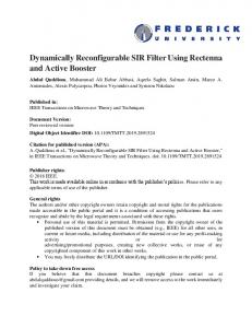
As both principal and emergency operators are of the same kind, the only information to share between these two tasks is the coordinate of the last processed pixel. When the principal task is aborted, the emergency task will go on from this point, and only the last few lines of resulting image will be degraded. However, used algorithms are often more complex than that, and following cases can occur: • The algorithm can be composed of several distinct steps (eg. several image scans with different pyramidal levels, as for the Region Segmentation). • The algorithm may use an irregular scan of the image (eg. automaton based algorithms). • The result may be a list of image features (eg. a list of regions, of edges, etc.). Each time, the means to use the Deadline Mechanism and the choice of the emergency operator must be carefully adapted to the specific characteristics of nominal algorithm. If the principal algorithm can be divided in several steps, a status variable shall be shared between the two tasks, to tell which step has been interrupted. According to this value, several adapted emergency processing can be run. If the image is not scanned linearly, it would be probably well advised to use an emergency task that processes the whole image again. At last, if the role of the principal task was to extract some image features as regions or edges, it may be useful to mend the extracted features on the line of darn3 , according to applicative context. The purpose of the vision processing may require an accurate knowledge of several properties of the image, dependent of the accuracy of operators results; if the line of darn runs across some of these features, this ones may have to be melt so that extracted high-level information is precise. For example, if a mission consists in detecting any colored regions (that possibly are obstacles), the fact that a region may be split in two on both sides of the line of darn is not a problem. On the contrary, if the system has to detect all regions greater than a specified size, it is mandatory to mend the results of the two processes to melt regions that are on the line of darn. In case image features do not have to be sorted (to detect the biggest colored region for example), another possibility is to validate the incomplete results of primary task if its giving up has occurred at the very end of the process: in other word, we accept that a tiny part of the image is not processed. In the particular case of the emergency algorithm requiring specific dimensions for its input data, it must be taken 3 The line of darn is the frontier between the part of the image processed by one operator, and the part processed by another. In our case, these operators are the principal and the emergency ones.
de Cabrol et al./ Dynamically Reconfigurable Real-Time Vision System for Autonomous Mobile Robotics.
into account to choose from which point process must continue (Fig. 8(d)). For example, if the emergency operator can only process images which dimensions are power of 2, it will have to start from a point already processed by the principal operator, in order that the second part of the image has the good size. In this case, since a part of the image is processed twice, one can choose to use the results of the one or the other for this area. It could also be possible to produce more accurate results from a combination of both. In all other cases, to simplify the darning problems with the extracted image features (Fig. 8(c)), the emergency operator can still start again from the beginning of current image line, so that the frontier is horizontal. Nevertheless, the major difficulty with continuing the process with another algorithm is that the existing operators must be adapted to enable the darning.
(a) Result of aborted principal process.
(b) Immediate darn. (c) Darn at the be- (d) Darn on an area ginning of the line. which dimesions are power of 2.
Figure 8 DM : strategies for darning.
5.2
Use of Cl´ eopatre Imprecise Computation.
It is not self-evident to use properly the Imprecise Computation mechanism. This mechanism enables to make one task to be followed by another one, running in the remaining free time. If an optional task outlasts its deadline, it is aborted and a special function defined by the user is activated immediately after. According to the role of the optional task, some precautionary measures vary. In the following, principal tasks will be named A and the next one B. The optional task of A will be A+. The type of A’s result is homogeneous to an image. 5.2.1 Case of a refining optional task. The purpose of a refining optional task is to modify results produced by a principal task so that they be more precise, or more adapted to the downstream processing. However, as these results have been produced by a principal task, they already are precise enough (out of design) to enable the robot to complete its mission. Therefore it is primordial that the optional task does not degrade the
9
results! In order to do so, two kinds of solutions exist. First one consists in creating an extra buffer dedicated to A+, so that this task reads A’s results but do not modify them. If A+ is completed before its deadline, its last action will be to update a flag or a pointer, to tell B that the best input data to use are in A+’s buffer. This implies that A and A+’s buffers have the same size, which requires another allocation of a chunk of memory (about the size of an image). A second solution can be used if an image partially processed by A+ is exploitable. This requires that A+ processes in a single scan, and that it improves locally the image. Then, if an optional task is aborted because it has lasted too long, it would have only small consequences. But this solution must not be used if this abortion causes a too important discontinuity in the result image, and provoke errors from B task. 5.2.2 Case of an independent optional task. If an optional task is an independent processing, the designers must think about the reason of this task they want to implement. As an activation of this task is unpredictable and irregular, they must ask themselves what would be the benefit of the produced results. If these results are necessary for the accomplishment of the mission, this task should perhaps be a regular and periodic task, so that the results are regularly updated. On the contrary, if those are not mandatory, the next tasks that use them as input must be examined, in order to decide if it would be better to use a classic task with a low periodicity. Some vision processing operators can use irregular input data, for example to update a 3D reconstruction from a single image [39] , but such a case is extremely rare. Furthermore, if such an operator was implemented as an optional task it would not overload the processor, but meanwhile nothing guarantees its running. Nevertheless, one of the main asset of these optional tasks is that they run only during free time remaining after the scheduling of the principal and emergency tasks. The use of this mechanism contributes to exploit the available computation time at best without overloading the system. So it is very profitable to try to make use of it. The most interesting use of this mechanism for an independent processing may be the calculation of some quality measurements on the results of principal operators. The sudden abortion of this computation does not have any bad consequence on the running of the whole system. On the contrary, if the calculation is completed and its result shows that an operator must have its parameters updated, the optional task can emit a signal to the manager task that will reconfigure tested operator.
6
Conclusion.
Cl´eopatre framework contains several innovative features for scheduling and fault tolerance, that we have turned to good account in our field of research: real-time vision for mobile robotics. Especially, we have shown that these mechanisms could enable to run a vision system on a hardware designed for regular situations (thus without the usual oversize necessary to deal with the exceptional ones), while ensuring ro-
10
International Journal of Automation and Computing 04(1), January 2007
bustness as design includes a minimal running mode. This is particularly important to develop systems that are both safer and less expensive. Our experiments let us define a set of rules to use at best the dynamic reconfiguration for Vision Processing. This foretells an evolution of the way to design a vision processing chain, where one will not reason by operator but by couples of complementary operators, so that more sophisticated strategies of dynamic reconfiguration can be used, that avoid redundant processings and achieve the best final result in the least duration.
[14] “RTAI,” http://www.rtai.org.
References
League,”
[17] N. Abel, D. Demigny, L. Kessal, and N. Boudouani, “Mise en oeuvre de la reconfiguration partielle sur l’architecture reconfigurable ARDOISE,” in Proceedings of the JFAAA, Monastir, Tunisie, Dec. 2002, pp. 45–48. [Online]. Available: http://publi-etis.ensea.fr/2002/ADKB02
[3] M. Bowling and M. Veloso, “Motion control in dynamic multi-robot environments,” in Proceedings of The 1999 IEEE International Symposium on Computational Intelligence in Robotics and Automation (CIRA’99), Monterey, Nov. 1999.
[18] N. Abel, L. Kessal, and D. Demigny, “Mise en oeuvre du lisseur de Deriche sur l’architecture reconfigurable dynamiquement ARDOISE,” in GRETSI, T. Paris, Ed., vol. I, Paris (France), Septembre 2003, pp. 376–379. [Online]. Available: http://publi-etis.ensea.fr/2003/AKD03
[1] Cybernetix, “BROKK & SAMM, remote intervention vehicle (dismantling operation),” datasheet, Aug. 2005. [2] “RoboCup Small-Size http://www.robocup.org.
[4] Cornell University, “Instruments: panoramic camera (PanCam),” http://athena.cornell.edu/the mission/ins pancam.html. [5] J. Gangloff, “Asservissements visuels rapides d’un robot manipulateur 6 degr´es de libert´e,” PhD Thesis, Universit´e Louis Pasteur, 1999. [6] V. Hugel, P. Bonnin, and P. Blazevic, “French LRP team’s description,” in Robocup, 2000, pp. 615–618. [7] V. Hugel, T. Costis, P. Bonnin, and P. Blazevic, “2005 RoboCup technical report,” LRV, Tech. Rep., 2005. [8] M. Silly and T. Garcia, “Cl´eopatre : Un systme d’exploitation temps r´eel composable et ouvert bas´e sur Linux/RTAI,” LINA,” Rapport de Recherche, Oct. 2004. [9] P. Bonnin and A. de Cabrol, “Projet RNTL Cl´eopatre, COTS vision robotique : rapport final,” L2TI, Tech. Rep., 2005. [10] T. Garcia, “Conception et d´eveloppement de composants pour logiciel temps-r´eel embarqu´e,” PhD The´ sis, Ecole Centrale de Nantes, LINA, Nov. 2005. [11] A. de Cabrol, “Syst`eme de vision robuste temps-r´eel dynamiquement reconfigurable pour la robotique mobile.” PhD Thesis, Universit Paris 13, 2005. [12] “RoboCup Rescue,” http://www.rescuesystem.org/ robocuprescue. [13] A. de Cabrol, P. Bonnin, V. Hugel, P. Blazevic, and M. Silly-Chetto, “Video rate color region segmentation for mobile robotic applications,” in SPIE, Applications of Digital Image Processing XXVIII, vol. 5909, 2005.
[15] R. Bourguiba, “Conception d’une architecture mat´erielle reconfigurable dynamiquement d´edi´ee au traitement d’images en temps r´eel,” PhD Thesis, de l’Universit´e de Cergy Pontoise, July 2000. [16] D. Demigny, M. Paindavoine, and S. Weber, “Architecture ` a reconfiguration dynamique pour le traitement temps r´eel des images,” Technique et Science de l’Information, Special Issue Architectures Reconfigurables, vol. 18(10), pp. 1087–1112, Dec. 1999.
[19] S. Bouchoux, E.-B. Bourennane, and J. Mitran, “Implantation du d´ecodeur arithm´etique de JPEG2000 se basant sur la reconfiguration dynamique des FPGAs,” in Journ´ees Francophones de l’Ad´equation Algorithmes-Architectures (JFAAA’2005), Jan. 2005, pp. 215–219. [20] R. Bajcsy, M. Mintz, and E. Liebman, “A common framework for edge detection and region growing,” University of Pennsylvannie, Tech. Rep., Feb. 1986. [21] H. L. Anderson, R. Bajcsy, and M. Mintz, “A modular feedback system for image segmentation,” University of Pennsylvannie, Tech. Rep., June 1987. [22] M. Salotti, “Gestion des informations dans les premi`eres tapes de la vision par ordinateur,” PhD Thesis, Institut National Polytechnique de Grenoble (INPG), Jan. 1994, 25 janvier 1994. [23] K. Chehdi, “Traitement num´erique du signal et images multispectrales et multimodales,” Villetaneuse, France, Jan. 2005, invited conference at the L2TI. [24] K. Chehdi, B. Vozel, C. Kermad, and M.-P. Vandecandelaere, “A blind system to identify and filter degradations affecting an image,” in IEEE ICSP’2000, International Conference on Signal Processing, Beijing, China, Aug. 2000. [25] C. Millour and A. Lanusse, “Intgration de m´ecanismes pr´eattentifs en analyse par vision de sc`enes dynamiques,” in 2nd scientific workshop TIPI-Aussois, 1988. [26] M. Silly, A. Marchand, and T. Garcia, Guide d’installation et d’utilisation de Cl´eopatre, Oct. 2004.
de Cabrol et al./ Dynamically Reconfigurable Real-Time Vision System for Autonomous Mobile Robotics.
[27] N. C. Audsley, “Deadline monotonic scheduling,” Department of Computer Science, University of York, Tech. Rep. YCS 146, Oct. 1990. [28] C. L. Liu and J. W. Layland, “Scheduling algorithms for multiprogramming in a hard-real-time environment,” Journal of the ACM, vol. 20, no. 1, pp. 46–61, 1973. [29] M. Silly-Chetto, “The EDL server for scheduling periodic and soft aperiodic tasks resource constraints,” Real-Time Systems, vol. 17, pp. 1–25, 1999. [30] G. C. Buttazzo and F. Sensini, “Optimal deadline assignment for scheduling soft aperiodic tasks in hard real-time environments.” IEEE Trans. Computers, vol. 48, no. 10, pp. 1035–1052, 1999. [31] L. Sha, R. Rajkumar, and J. Lehoczky, “Priority inheritance protocols: An approach to real-time synchronization,” IEEE Transactions on Computers, vol. 39, no. 9, pp. 1175–1185, 1990. [32] M. Chen and K. Lin, “Dynamic priority ceilings: a concurrency control protocol for real-time systems,” Real-Time Systems, vol. 2, no. 4, pp. 325–346, 1990. [33] H. Chetto and S.-C. Maryline, “An adaptive scheduling algorithm for a fault-tolerant real time system,” Software Engineering Journal, vol. 6, no. 3, pp. 93– 100, May 1991. [34] J. Liu, J. Lin, and S. Natarajan, “Scheduling algorithms for multiprogramming in a hard real-time environment,” in Proceeding of the 8th real-time system symposium, San Francisco, CA, USA, Dec. 1987, pp. 252–260. [35] M. Mangolini, “Apport de la fusion d’images satellitaires multicapteur au niveau pixel en t´el´ed´etection et photointerpr´etation,” PhD Thesis, Universit´e de Nice Sophia Antipolis, 1995. [36] L. Kuntz-Sliwa, “Optimisation d’une configuration multi-capteur donn´ee : fusion pixel,” PhD Thesis, Institut National Polytechnique de Toulouse (INPT), Feb. 1996. [37] A. Rosenfeld and J. L. Pfalz, “Sequential operations in digital picture processing,” in Journal of the Association for Computing Machinery, vol. 13(4), 1966, pp. 471–494.
11
[38] J. Bruce, T. Balch, and M. Veloso, “Fast and inexpensive color image segmentation for interactive robots,” in International Conference on Intelligent Robots and Systems (IROS’00), vol. 3, 2000, pp. 2061–2066. [39] M. Herman and T. Kanade, “The 3D MOSAIC scene understanding system: incremental reconstruction of 3D scenes for complex images,” in Readings in computer vision: issues, problems, principles, and paradigms. San Francisco, CA, USA: Morgan Kaufmann Publishers Inc., 1987, pp. 471–482. Aymeric de Cabrol graduated from ESME Sudria Engineering School in Paris, France, in 2001. He received his M.Sc. in Automatic Control from ENSAE Sup’a´ ero in Toulouse, France, in 2002 ad the Ph.D. degree from the Paris 13 University, France, in 2005. He is currently associate researcher at the Laboratory of Transport and Processing of Information, L2TI. His research interests include vision processing for mobile robotics. Thibault Garcia received his M.Sc. in Distributed Computing, then the Ph.D. from University of Nantes, France, respectively in 2001 and 2005. His field of research includes real-time operating system and scheduling issue. Dr. Garcia is currently at the head of Revaweb company.
Patrick Bonnin received his agr´ egation in Physics in 1985, then his M.Sc. in Physical Measurement in Remote Sensing and the Ph.D. from University Paris 7, France, respectively in 1986 and 1991. Then he became associate professor in 1992, and professor in 2000. His field of interest includes Real-Time Robotic Vision, especially for legged robots. He is currently professor at ISTY School of Engineering of the University of Versailles, France. Maryline Chetto received her M.Sc. in Automatic Control, the Ph.D. degree in Computer Science and the HDR from University of Nantes, respectively in 1982, 1984 and 1993. She is currently professor at the University of Nantes, France. Her research is conducted in the Group of Real-time systems of the research institute of communications and cybernetics (IRRCyN). Her area of interest includes scheduling and fault-tolerance in real-time systems. She has published more than 60 journal articles and conference papers in the area of real-time operating systems. Professor Chetto has been the leader of a French national R&D ´ project, namely CLEOPATRE, supported by the French government, which aims to provide free open source real-time solutions.