1
VMI 2.0: A Dynamically Reconfigurable Messaging Layer for Availability, Usability, and Management Scott Pakin and Avneesh Pant
Abstract—As system area networks (SANs) grow in size, and organizations pool their SANs over the wide area into even larger compute platforms (commonly known as grids), it becomes increasingly difficult both to manage and to exploit the available resources. The key issues is the space of grid computing are availability, reliability, and management. Availability is an issue, as network hardware is more likely to fail in a large network than in a small one. Usability is an issue, as different SANs use different networks, and inter-SAN communication frequently uses different networks from intra-SAN communication. And management is an issue, as it is more difficult to find and isolate problematic components of a large, heterogeneous system than a small, homogeneous one. This paper introduces VMI 2.0, a middleware communication layer that addresses the issues of availability, usability, and management in the context of large-scale SANs interconnected over wide-area grids. Novel features include the ability to stripe data across heterogeneous networks, the ability to fail over from one network onto a heterogeneous network, and the ability to add data filters and other features dynamically, remotely, and even on per-connection bases.
A. Motivation
Given point-to-point communication at nearhardware speeds, the next big challenge for cluster and grid computing is to provide features and services that enhance availability, usability, and management. This was our goal when implementing VMI 2.0, the second version of the Virtual Machine Interface communication middleware running at the National Center for Supercomputing Applications (NCSA).1 Grids—collections of SANs, storage servers, and other resources that lie scattered across the Internet—are a difficult environment to harness. However, because of their inherent scalability, they can serve as a source of massive computation power. Unlike a typical SAN, a grid is composed of heterogeneous networks, CPUs, and operating systems. Metacomputing systems such as Globus [7] and Legion [8] provide services to applications which are distributed across the grid. Examples of these services include authentication and authorization, diI. I rectory and naming services, and high-level file I/O. HEN gigabit networks, such as Myrinet [1], Note that all of these services rely on lower-level Giganet [2], and Gigabit Ethernet [3], started communication layers—usually sockets over IP—to to become commonplace on workstation clusters, the manage the actual communication. communication performance bottleneck shifted from This paper introduces VMI 2.0, our new middlenetwork hardware to the messaging software. A ware communication layer. Like a sockets layer, it number of highly optimized messaging layers—Fast abstracts away the underlying communication interMessages [4], Active Messages [5], and U-Net [6], faces and presents higher-level communication layto name a few—arose to bridge the gap between the ers with a consistent view of the network (Figure 1). performance achievable by the hardware and that obUnlike a sockets layer, though, VMI 2.0 can aggreserved by applications. As a result of these efforts, gate a number of disparate communication interfaces applications can observe point-to-point communicainto a coherent whole. For this to work, VMI 2.0 tion performance near that achievable by the raw netmust be cognizant of a variety of interface-specific work hardware. communication details:
W
Scott Pakin and Avneesh Pant are with the National Center for Supercomputing Applications, Urbana, Illinois, USA (e-mail:
[email protected],
[email protected]).
1 Currently, VMI 1.0 is used by all applications on all of NCSA’s production clusters.
2
Application MPI
Sockets Globus Legion
VMI 2.0 VIA
GM
TCP
InfiniBand
Myrinet
GigE
Fig. 1 R VMI 2.0
Flow control
If a receiver has no space to receive a message, does the sender block, or is the message dropped? Buffer management Do memory regions have to be registered before they can hold communication data? Packetization How large of a message can the interface send at once? What message sizes are most efficient? Error detection Does the interface detect data errors? Link errors? Or is data silently dropped? Message ordering Does the interface deliver data in order? It is unreasonable to expect application writers— or even metacomputing service providers—to know all of the characteristics of all of the networks that a progam will run on. Sockets interfaces do hide most of these details; however, they are too heavyweight a solution and, as a result, tend to perform poorly on SANs relative to lighter-weight interfaces. As Figure 1 illustrates, VMI 2.0 serves as the middleware layer that bridges heterogeneous interfaces with metacomputing servers, such as Globus and Legion, and higher-level programming interfaces, such as MPI [9] or even sockets. B. VMI 1.0 VMI 1.0 [10] was our first attempt at transparently aggregating multiple lower-level communication interfaces. The goal was to enable binary portability of MPI applications across NCSA’s various clusters. These clusters—sometimes even sets of nodes within a single cluster—contain dissimilar network configurations. Some may have experimental new network
interfaces on a few nodes; others may lack a particular interface while awaiting a replacement for a failed part. VMI 1.0 defines a basic network abstaction that supports point to point communication. To handle interface-specific communication details, VMI 1.0 uses dynamically loadable modules, each of which implements a simple API (send, receive, connect, disconnect, etc.) in terms of whatever a particular network interface provides. During initialization, a process loads the modules listed in a machinespecific configuration file, which describes the network interfaces that that machine contains. C. VMI 2.0 After VMI 1.0 ran for some time on NCSA’s production clusters, we found that users appreciated the ability to run their applications unmodified on differently configured clusters. In particular, users liked being able to use shared memory for high-speed communication within an SMP and without needing to know in advance which processes would lie in the same SMP. In addition, cluster administrators liked being able to mark a network as unavailable (e.g., for upgrades) merely by commenting out the apppropriate line in the machine-specific configuration file. Extended use of VMI 1.0 revealed a number of limitations of its design. First, only at process startup time could a process select a network to use to communicate with each of its neighbors. If a network card or switch failed, the application would need to be restarted, even if an alternate network could be used to restore global connectivity. Ideally, a messaging layer should transparently switch the application onto an alternate network. Second, it is common for NCSA’s clusters to contain multiple networks, such as Gigabit Ethernet and Myrinet, yet a VMI 1.0 process statically determines which of those to use to contact each of its peers. Ideally, a messaging layer should stripe data across all available networks to achieve better bandwidth. Third, there is no way to monitor the health of all of the cluster’s networks from a remote workstation. And while it was nice that an administrator could mark networks as available or unavailable, his changes would apply only to new jobs, not to running ones. Ideally, a messaging layer should provide remote monitoring and management. Finally, VMI 1.0 was designed for SANs and parallel programs—static sets of mutually cooperating processes that communicate over low-latency,
3
high-bandwidth, low-error networks. However, the advent of the TeraGrid project (and NCSA’s participation therein) necessitates a messaging layer that can work efficiently over both wide-area links and SANs and that can handle dynamic client/server and peer-to-peer communication patterns in addition to static, mutually cooperating processes. VMI 2.0 is the result of those desiderata. While VMI 2.0 retains VMI 1.0’s multiple-network support, it is a completely redesigned messaging layer that greatly expands upon its predecessor. We identified the following features as those necessary to enhance the availability, usability, and management of grid and cluster communication. 1) Data striping across heterogeneous networks: By striping data across multiple networks, a messaging layer can achieve greater communication bandwidth than were it limited to a single network. Because VMI 2.0 runs above the lower-level, devicespecific messaging layers, it is able to stripe data not just across multiple networks of the same type, but also across heterogeneous networks. As far as we know VMI 2.0 is the first messaging layer to support heterogeneous data striping. 2) Failover across heterogeneous networks: Employing a similar mechanism to that used for striping, VMI 2.0 can also do heterogeneous failover. If, for example, a Gigabit Ethernet cable comes unplugged, or a Myrinet switch is powered off, an application can transparently continue to utilize a remaining network. As far as we know VMI 2.0 is the first messaging layer to support heterogeneous failover. 3) Scalability upwards of many thousands of nodes: Not only are organizations such as NCSA building individual clusters consisting of thousands of compute nodes, but an effort is underway to link thousands of clusters together into an Internet-wide grid of available compute power. To be effective in a grid environment, VMI 2.0 localizes all decisionmaking to minimize the impact of wide-area delays on SAN performance. 4) Dynamic feature configuration: VMI 2.0 utilizes a “plug-in” module interface, with which VMI 2.0’s features can be extended. Because these modules can be installed into and removed from running programs, an application need load only those modules that are actually required, thereby not sacrificing performance on unused features. Modules can be global to an entire application or local to an individual network connection. For example, an ap-
plication may load a profiling module to profile all network traffic but load an encryption module only on those links that traverse clusters. 5) Portability: All of the concepts underlying VMI 2.0’s design are platform independent; only a few isolated functions need to be rewritted to port VMI 2.0 to a new operating system or processor architecture. VMI 2.0 currently runs on Intel IA32 and IA64 systems as well as on Sony’s MIPSbased PlayStation 2 (!). Different networks are supported with modules. Merely by writing a module to interface to a (typically vendor-supplied) lowerlevel messaging layer, a developer can utilize all of VMI 2.0’s features on a new type of network. 6) Remote monitoring: A system administrator can manully assess the health of a single application running on a small cluster. By integrating process monitoring into the VMI 2.0 middleware, we helps users ensure that their applications are running smoothly on an Earth-spanning cluster of clusters and system administrators see which nodes or network hardware need repairs. 7) Remote management: Not only does VMI 2.0 make process state visible across the Internet, but it provides control over individual nodes and processes (or groups thereof). For instance, a user trying to debug a program can dynamically load a packetlogging module into a running application—and unload the module when the bug is found. Using a similar mechanism, a system administrator can mark a particular network unavailable before upgrading its device drivers or firmware. (VMI 2.0 could then fail over onto one of the other networks, transparently to running applications.) 8) Support for both parallel and distributed computing models: VMI 2.0, like VIA [11], deals exclusively with point-to-point connections; it has no concept analogous to an MPI communicator [9], a group of processes exhibiting mutual trust. The connection approach, although a lower-level abstraction, can be used to implement both the parallelcomputing model (e.g., MPI) and the distributedcomputing model (e.g., most transaction systems). Of course, it is important to provide all of the aforementioned features without sacrificing raw communication performance. The rest of this paper is organized as follows. Section II describes the VMI 2.0 architecture and how we were able to achieve the goals listed above. We
4
evaluate the performance of VMI 2.0 in Section III. In Section IV we describe the research projects that are most closely related to VMI 2.0. Finally, we draw some conclusions about VMI 2.0 in Section V. II. I VMI 2.0 is implemented as a user-level messaging layer plus a set of dæmon processes. The basic architecture is modeled after the Windows NT kernel architecture [12]. The reason we used NT as a design basis is that we believe the architecture is extremely extensible, yet exacts minimal performance penalty due to its inherent asynchronicity—features we find as applicable to messaging layers as to operating systems. A. IRB processing model VMI 2.0 devices, the loadable modules that talk to the network or filter communication data, are linked together on chains. VMI 2.0 initially defines two chains—the default send chain and the default receive chain—although more can be created dynamically. When a message is sent, each device on the send chain has an opportunity to modify it (e.g., to transform the data or attach a header) before passing the message to the next device and finally into the network. Similarly, when a message is received, each device on the receive chain has an opportunity to modify it (e.g., to transform the data or remove a header) before passing the message to the next device and finally to the application.2 Messages and control instructions are passed between devices exclusively using I/O request blocks (IRBs). Figure 2 depicts the key fields within an IRB. IRBs contain a stack, a status field used for return values, the connection the IRB is associated with, and miscellaneous other pieces of state. The most important is the IRB stack. Each element of the stack encapsulates the state for one of the devices on the chain that the IRB was dispatched onto. The command field specifies the current IRB type (Table I). Message data is passed to the device with the slab field, and other data is passed in and out with the input args and output args fields. When dispatching a new IRB or forwarding an existing IRB, a device 2 In the context of this paper, “application” can also mean a higherlevel messaging layer, such as MPI [9].
can specify a function to call when the IRB is completed and a context (an arbitrary pointer) to pass to that function. When an IRB reaches the last device on a send chain (known as a “sink device”), the device has two options for dealing with the IRB. If the IRB can be processed immediately, the device completes the IRB, causing all of the completion functions to be called. If, however, a long IRB processing delay is expected (as in the case of a connect IRB), the device pends the IRB and completes it (asynchronously) as soon as it can. Pending an IRB enables the application to make progress even when VMI 2.0 is stalled. B. Data model VMI 2.0 encapsulates data using a number of different data structures. (Figure 3). At the lowest level is a buffer, which represents a contiguous block of memory that can be transmitted over a network. Most user-level messaging layers, such as VIPL [11] and GM [13], require data to be “registered” (which usually implies pinning it into physical memory) before it can be used in a communication operation. The VMI 2.0 API contains calls to register and deregister buffers, and these calls are forwarded to the source and sink devices on demand. Because buffer registration is usually expensive and typically restricted to page-aligned regions whose size is a multiple of the OS page size, it would be inefficient to register every piece of communication data individually. VMI 2.0 therefore defines a buffer op structure, which represents a contiguous block of memory within a buffer. A slab contains multiple buffer ops and is used to represent discontiguous data. To reduce memory copies and improve performance, VMI 2.0 implements gather and scatter operations. These are implemented in terms of adding (respectively, removing) buffer ops to (respectively, from) slabs. An interesting capability that VMI 2.0 provides to higher-level messaging layers is the ability to “grab” a slab. That is, if a slab arrives from the network, but a messaging layer is unable to process the data immediately, the messaging layer can acquire ownership of the slab. The VMI 2.0 core and loadable devices are then prohibited from recycling the slab memory. After processing the data, the messaging layer releases ownership back to VMI 2.0, which can then reuse the memory. The importance of slab-grabbing is that it obviates the need to copy data when it cannot be processed immediately.
5
IRB
State for device 0 - command
stack status connection misc. state
State for device 1
input args output args slab completion function completion context
...
Fig. 2 S IRB
TABLE I IRB
Type
Meaning to a device
Attach Detach Connect Disconnect Connect request Disconnect request Send Receive Alert
Attach yourself to the specified chain. Detach yourself from the specified chain. Establish a connection to the specified peer. Tear down the given connection. A given peer wants to connect to us. A given peer wants to disconnect from us. Send the given slab on the given connection. A slab has arrived on the given connection. Notify an administrator to a given error condition.
Slab Stream
Slab
Slab
Slab Slab
Slab Stream
Slab
Slab Slab
Slab Buffer Op Buffer Op Buffer Op
Buffer
Buffer Fig. 3
VMI 2.0
Stream
Process B
Process A
Connection
6
Slabs are transmitted as datagrams on a stream, which is a directional connection between two processes. There can be any number of streams linking two processes. That is, the data within a slab are always delivered in the order sent, but slabs are delivered unordered relative to each other. Each streams is associated with a bidirectional connection. At most one connection binds each pair of processes, and it is assumed that connection setup is comparatively costly, while stream setup is comparatively cheap. C. VMI 2.0 core Table II enumerates the components that constitute the VMI 2.0 core. Only the Connection Manager and Stream Manager are aware of remote processes. All of the other components work exclusively with local VMI 2.0 objects. At startup, a process loads whatever devices it needs (using the Device Manager), uses the Chain Manager to order these devices on various device chains—send chain, receive chain, alert chain, and any other chains the process needs— and establishes connections with remote processes (using the Connection Manager). To send a message, the process associates the data with a set of buffers and buffer ops3 (using the Buffer Manager), gathers the buffer ops into a slab (using the Slab Manager), and calls upon the Stream Manager to send the data. The Stream Manager dispatches a send IRB (using the I/O manager) down the send chain. The final device on the send chain injects the message into the network. The reverse operations occur on the receive side, with the message being received by a device, which then dispatches an IRB up the receive chain. The Stream Manager picks the transformed message off of the receive chain and delivers the message to the process. The VMI 2.0 core is divided into separate managers for modularity. Although the current static linkage ensures availablility, we plan eventually to offload as many managers as possible into dynamically loadable devices. This will enable parts of VMI 2.0 to be upgraded or customized independently of other parts. For example, a replacement Connection Manager might use a directory server to query remote process status. Or a replacement Device Manager might download missing device files from the Internet on demand, install them, and continue running. 3 A buffer is analogous to a VIA [11] memory region, and a buffer op is analogous to a VIA descriptor.
D. Dæmons VMI 2.0 provides remote monitoring and management facilities, which enables users and system administrators to observe and control applications and computers. These facilities are embodied in a collection of dæmon processes. Because VMI 2.0 is designed to handle enormous systems organized not merely as SANs, but as collections of large SANs distributed across the Internet, scalability is a key concern. The VMI 2.0 dæmons are therefore organized hierarchically, as described in Table III. VMI 2.0 includes a monitoring library that provides all of the back-end functionality that a monitoring application needs to acquire detailed information about any node or VMI 2.0 process on the grid. To date, we have implemented an application called Yama that gathers data with the monitoring library and uses that data to present a 3-D view of all of the SANs, nodes, and VMI 2.0 processes on the grid. Because any front end can use the monitoring library, other user interfaces are possible, as well. Developers can therefore implement customized interfaces for their particular interests and uses of the grid. III. E Section II described the implementation of VMI 2.0 and how its novel IRB-based architecture and support for dynamically loadable modules yield extreme usage flexibility. In Section III, we analyze the efficiency of VMI 2.0’s design. Our goal is to demonstrate that VMI 2.0’s flexibility does not come at too high of a price, i.e., that a cluster’s availability, usability, and management can be increased without exacting an undue amount of performance. It is difficult to devise an experimental setup to fairly analyze a system that is as dynamic and reconfigurable as VMI 2.0. We chose to use a consistent—albeit non-minimal—configuration for all of the experiments in this section. In this configuration, VMI 2.0 loads two devices on each chain: a GM+Myrinet source/sink device and a “transfer” device, a somewhat complex intermediate device that handles device failover.4 Although the transfer device serves little purpose in a one-network configuration, we include it in our configuration to demonstrate that even a large device does not contribute noticeably to the critical path of communication. At 4 The transfer device will eventually also handle data striping, but that feature is not yet functional at the time of this writing.
7
TABLE II VMI 2.0
Subsystem
Remote Operations
Alert Buffer Chain Connection Device I/O Slab Stream
✔
✔
Raise alert Allocate, deallocate, register, and deregister buffers; allocate and deallocate buffer ops (operations on data within a buffer) Allocate/deallocate chains, attach/detach devices to chains Establish and tear down connections with peer processes Load/unload devices, poll devices Dispatch IRB, complete IRB, pend IRB Allocate/deallocate slabs, push/pop buffer ops onto a slab, copy data from a slab Begin stream, send a slab, end stream TABLE III VMI 2.0
Dæmon
Number
Purpose
VMIeyes
One per node
Reaper
One per SAN
Nark
One per grid
Keeps track of all of the VMI 2.0 processes on the node and the state of each process’s devices. Forwards management messages from the Reaper dæmon to a process’s management device (if any). Forwards event notifications from processes to the Reaper. Keeps track of all of the VMIeyes dæmons in the SAN. Used by the Nark dæmon to query or control the state of any node or process in the SAN. Keeps track of all of the Reaper dæmons in the grid. Used by monitoring and management applications to query or control the state of any node or process in the grid.
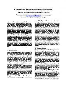
a minimum, the transfer devices redispatches every IRB it receives, because it needs to receive the final IRB return code to detect if the IRB has failed and cannot be retransmitted on the same network (e.g., due to a hardware failure). If we can show that this additional IRB processing does not noticeably degrade performance, we can claim that the IRB model is a reasonable way to achieve dynamicity in a messaging layer. We ran our experiments on a cluster comprised of 1 GHz x86 processors and interconnected with both Myrinet and Gigabit Ethernet. A. Point-to-point performance We start by examining VMI 2.0’s raw bandwidth and latency performance. Figure 4 shows the bandwidth of our baseline VMI 2.0 configuration (labeled
“GM and Xfer devices” in the figure) as message size varies. To determine the overhead caused by the transfer device, we compare this to the bandwidth of a configuration in which the transfer device is absent (GM device only). The third curve in Figure 4 represents the bandwidth measured by the (non-VMI 2.0) bandwidth program that ships with GM (Raw GM). There are two observations one should make from looking at Figure 4. First, the difference between the GM and Xfer devices and GM device only curves is negligible. This is a good sign, because it shows that the extra overhead caused by IRB allocation, dispatch, transfer, and completion plus all of the devicespecific overhead does not impact raw bandwidth. We can therefore hypothesize that adding more devices would likely add no more cost than the difference between the GM and Xfer devices and GM device only curves.
8
100,000
180
Latency (microseconds)
Bandwidth (MB/s)
160 140 120 100 80 60 40
10,000
1,000
100
10
20 0 1 2 4 8 16 32 64 128 256 512 1,024 2,048 4,096 8,192 16,384 32,768 65,536 131,072 262,144 524,288 1,048,576 2,097,152
0 1 2 4 8 16 32 64 128 256 512 1,024 2,048 4,096 8,192 16,384 32,768 65,536 131,072 262,144 524,288 1,048,576 2,097,152
1
Message size (bytes)
Message size (bytes)
GM and Xfer devices
GM device only
Raw GM
GM and Xfer devices
GM device only
Raw GM
Fig. 4
Fig. 5
VMI 2.0
VMI 2.0
The second observation is that VMI 2.0 is nearly as fast as the underlying GM layer for small messages. Unfortunately, as message size increases, VMI 2.0 peaks out at only 155 MB/s, relative to GM’s 166 MB/s. This discrepancy corresponds to an overhead of 0.8 µs on VMI 2.0’s long-message critical path, corresponding primarily to buffer management and data reordering. The other Hockney parameters are t0 = 8.67 µs for GM, 9.47 µs for VMI 2.0, and n1/2 =1,329 for GM, 1,530 for VMI 2.0.
bottlenecks lie. Figure 6 contains a timeline of a message transmission and reception, with each noteworthy event labeled with its duration. Time flows from top-to-bottom on the page.5 . The largest single cost is the overhead observed by the GM device when preparing data to be injected into the network. IRB handlng tends to be fairly inexpensive, though—usually taking under 0.15 µs. This is promising, because it justifies VMI 2.0’s IRB model as not being inherently slow. Rather, the devices are what need to be optimized. Figure 5 shows the VMI 2.0 latency, which has As a point of explanation, after sending a message, a minimum of 16.52 µs when the transfer device is used, 14.93 µs when it is not. For comparison, GM’s a process can compute for an arbitrary length of time. minimum latency is 10.37 µs. While VMI 2.0 adds a The subsequent Complete IRBs occur when VMI 2.0 large percentage to the raw GM latency, the per-byte is polled for possible progress. cost does diminishes with increased message size. This was largely to be expected. Because VMI 2.0 C. Application performance passes data by reference (as illustrated in Section IIB), it rarely needs to copy data. As a result, the comAs the final experiment used to investigate the perparatively slow-growing per-packet and per-message formance impact of adding VMI 2.0 to the critical costs account for most of the variable part of the to- path of communication, we used MILC [14], a large, tal. SU(3) lattice gauge theory application framework. We ran the ks dynamical application, a simulation using dynamical Kogut-Susskind fermions. B. Overhead analysis To further reduce VMI 2.0’s overhead and latency, we must first determine where the communication
5 For space reasons, the receiving process is shown to the left of the sending process instead of below it.
9
Receiving process
Sending process
Application
VMI 2.0 core
Transfer device
GM device
Application
VMI 2.0 core
Transfer device
GM device
0.22 µs 0.72 µs
Begin stream End stream
0.16 µs
Dispatch IRB
0.11 µs
MILC MPI VMI 1.0
0.60 µs 0.15 µs
0.10 µs
0.64 µs Receive
Reorder
Start I/O Dispatch IRB
0.12 µs
9.50 µs Network latency
Dispatch IRB
0.62 µs
Start I/O Dispatch IRB
VMI 1.0 GM device
1.24 µs
Start I/O
Send data / Pend IRB
0.13 µs
VMI 1.0 TCP device
VMI 1.0 VMIVMI device VMI 2.0 VMI 2.0 GM device
Fig. 7
0.29 µs
0.51 µs
Complete IRB
C MILC
0.16 µs Compute
0.28 µs
Pend IRB
Complete IRB Clean up
0.64 µs
Complete IRB
0.13 µs
Complete IRB
Fig. 6 VMI 2.0
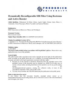
The experimental setup we used for MILC is slightly different from that used in the previous experiments. MILC is an MPI application, but we have not yet had time to port MPI to VMI 2.0. We do, however, have MPI running atop VMI 1.0. Hence, we decided to take advantage of VMI’s support for dynamic modules and quickly wrote a VMI 1.0 device called “VMIVMI”, which links with the VMI 2.0 library and implements the VMI 1.0 API in terms of the VMI 2.0 API. For our experiment, we benchmarked MILC with problem size L = 14 (≈ 7 minutes/run). We used three device configurations (Figure 7): • VMI 1.0 atop a VMI 1.0 GM device • VMI 2.0 atop a VMI 1.0 TCP device • VMI 1.0 atop a VMI 2.0 device, which, in turn, lies atop a VMI 2.0 GM device
Figure 8 shows the performance results in terms of MFLOPS/node. For small numbers of nodes, the performance of the three configurations is similar. However, for larger numbers of nodes, the VMI1+GM and VMI1+VMI2+GM curves remain near each other, while the VMI1+TCP performance drops off. The conclusion we can draw from this is that VMI 2.0’s overhead is low enough that VMI 2.0 does not significantly degrade application performance. That conclusion is based on two facts: • MILC is sensitive to network performance, as evidenced by the high-overhead VMI1+TCP performing noticeably worse than the lowoverhead VMI1+GM. • Adding VMI 2.0 to the critical communication path does not introduce enough overhead to greatly reduce MILC performance, as evidenced by the small distance between VMI1+GM
10
MFLOPS/node
120 100 80 60 40 20 0 1
2
4
8
16
32
Nodes VMI1+GM
VMI1+VMI2+GM
VMI1+TCP
Fig. 8 A (MILC)
and VMI1+VMI2+GM. In short, on both microbenchmarks and real applications, VMI 2.0 can add availability, usability, and management features without adversely affecting the performance of the underlying messaging layer. IV. R W VMI 2.0 provides a wealth of features and capabilities. While there is no exactly comparable system, the following works overlap ours in important ways. Coll, et al. [15] investigated a number of tradeoffs and design decisions surrounding multirail networks (i.e., multiple networks per node). They focused particularly on the dynamic selection of networks and the cost of using local versus global state when selecting. VMI 2.0, which implements data striping, can build upon Coll, et al.’s simulation results, which we hope will further increase VMI 2.0’s performance. While Coll, et al.’s study involved a comparatively large number of homogeneous networks (up to seven per node), Lumetta, et al.’s Clumps work [16] examined the tradeoffs in a high-speed messaging layer when using exactly two heterogeneous networks per node: an SMP bus for intra-node communication and a Myrinet network for inter-node communication. Although VMI 2.0 supports an arbitrary number of heteogeneous networks per node, many of the Clumps findings, such as the benefits of adaptively adjusting polling frequency on a per-network basis, are still applicable to VMI 2.0.
As mentioned in Section II, VMI 2.0’s basic architecture is modeled after that used in the Windows NT kernel [12]. Both VMI 2.0 and NT contain a set of core services (“managers”) that implement only basic functionality and a set of dynamically loadable modules that extend the basic functionality with more task-specific features. In both systems, the loadable modules can either talk directly to physical devices or modify data as it flows to or from another module. And in both systems, inter-module communication is performed quickly and statelessly by passing a generic structure (“IRB” in VMI 2.0, “IRP” in NT) from module to module. The reason we modeled VMI 2.0’s architecture after NT’s is that we believe the design is extremely extensible, yet exacts minimal performance penalty due to its inherent asynchronicity. We also drew inspiration from the Virtual Interface Architecture (VIA) [11]. As Table IV shows, the VMI 2.0 data model bears a strong resemblance to VIA’s. Both models allow gathering and scattering. Both expose memory registration at the API level. Both have notions of ordered units of data sent within larger, unordered units. And both are connectionoriented but support fast, logical connections within an established “physical” connection. The ability to grab slabs comes from Converse [17], which has an analogous feature. V. C Thanks to user-level messaging layers, nearhardware communication performance is often available to applications running within a SAN. We claim that availability, usability, and management are the next logical step needed to make wide-area clusters of SANs a feasible platform for high-performance computing. VMI 2.0 is the result of our efforts to produce a middleware layer that can tame these complex grid environments. VMI 2.0 both augments its base functionality and interfaces with lower-level messaging layers through “devices”—loadable modules that can transform and communicate data. Using these devices, VMI 2.0 provides the unique capability of being able to fail over from a downed network to a working one, even when the networks are of different types. This is done transparently; applications are unaware of their communication being switched from one network to another. With a similar mechanism, VMI 2.0 can aggregate bandwidth by striping
11
TABLE IV A VMI 2.0 VIA
VMI 2.0
VIA
Meaning
connection stream slab buffer op buffer
connection send/receive queue descriptor data segment memory region
“Physical” connection between pairs of processes Logical connection within a physical connection Scattered/gathered (i.e., discontiguous) message Contiguous fragment of data within a message Contiguous region of registered memory
to resume using the primary network. The VMI 2.0 dæmons are organized hierarchically and designed to VMI 2.0 devices are a powerful abstraction. They minimize communication over higher-latency links. VMI 2.0’s flexibility and extensibility are due to its enable users and system administrators to load and novel design, which separates core subsystems that unload features at run time, thereby incurring no provide only basic functionality, from loadable depenalty for unused features. Devices can be loaded vices, which manipulate and communicate data uson a per-connection basis. This facilitates grid coming a generic, IRB-based interface, from external dæputing by enabling different forms of communication mons, which shuttle control and status messages beto occur within a SAN and between SANs. For extween VMI 2.0 processes and monitoring and manample, an encrpytion device might be used for interagement applications. As this paper makes clear, SAN communication but not intra-SAN communiVMI 2.0’s architecture makes it an innovative way to cation. Network devices negotiate connectivity with increase the availability, usability, and manageability their remote peers; while a TCP device can connect of heterogeneous clusters of clusters and a promising any two VMI 2.0 processes on the grid, a Giganet demeans to harness the immense computing power of vice can communicate only with peers that are in the this promising new platform. same SAN, and a shared-memory device can communicate only with peers that are in the same comVI. F W puter. This protocol negotiation is abstracted away VMI 2.0’s ability to load generic devices onto from the application, which requests connections, a chain opens up limitless avenues for future rebut need not specify which network(s) to use to essearch. For example, one could use VMI 2.0 as tablish those connections. As a result, VMI 2.0 proa vehicle for investigating the performance potenvides binary portability across grid configurations. tial of compressing data before injecting it into the That is, an application that runs over an InfiniBand network. If different applications are found to pernetwork in one SAN can run without modification form better with different compression algorithms, it over a FibreChannel network in another SAN or even is a simple matter for VMI 2.0 to dynamically load over a grid that links those two hybrid SANs together the the most appropriate compression device for a using ATM. given application. A follow-on project could be to VMI 2.0 integrates a remote monitoring and man- study grid-based computing where some nodes exagement interface. With the help of a set of dæ- hibit asymmetric communication performance. A mon processes, network repair personnel can localize number of home networks—cable modems, ADSL, failed network connections from a single interface; a even 56K modems—give greater bandwidth in one user can add a profiling device to a running appli- direction than the other. By enabling different decation, profile the application’s communication be- vices to be loaded on each connection, VMI 2.0 havior, and remove the profiling device once enough makes it possible to compress only in the low-speed data has been collected; and a system administrator direction while leaving data uncompressed in the can instruct running applications to transfer over to high-speed direction. In addition to pursuing new research ideas through a backup network, upgrade the primary network’s firmware, and then allow the running applications VMI 2.0 loadable devices, future work also includes data across multiple networks, again, even heterogeneous ones.
12
adding new IRB types for enhanced functionality and performance. For instance, new IRBs may be used to support collective-communication operations, such as barriers, reductions, and multicasts, or one-sided operations, namely P and G. These could be implemented natively by networks and network interfaces that support them (e.g., InfiniBand [18] supports multicasts and P/G) and emulated on networks that do not. Because the IRB protocol specifies that a device must forward an unknown IRB to the next device in the chain, new IRB types will not break existing devices. Another major feature that could be implemented by extending the existing set of IRBs would be support for quality of service guarantees or real-time communication. A QoS device could manage the service negotiation and scheduling, using multiple devices either for higher schedulable bandwidth or for the ability to honor service guarantees even in the presence of network failures. Finally, a noteworthy necessity for VMI 2.0 is a set of policy decisions for data striping. Additional research is needed to determine how best to divide data across heterogeneous networks, each of which is optimized for a different range of message sizes and each of which exhibits different bandwidth, overhead, and—on a per-connection basis—latency characteristics. R [1] Nanette J. Boden, Danny Cohen, Robert E. Felderman, Alan E. Kulawik, Charles L. Seitz, Jakov N. Seizovic, and Wen-King Su, “Myrinet—a gigabit-per-second local-area network,” IEEE Micro, vol. 15, no. 1, pp. 29–36, Feb. 1995, Available: http: //www.myri.com/research/publications/Hot.ps. [2] Aberdeen Group, Inc., Boston, Massachusetts, Giganet: Building a Scalable Internet Infrastructure with Windows NT and Linux, 1999, Available: http://www.giganet.com/ technology/whitepapers_lookup.asp?id=5. [3] LAN/MAN Standards Committee, “IEEE standard 802.3, part 3: Carrier sense multiple access with collision detection (CSMA/CD) access method and physical layer specifications,” Standard 802.3, IEEE Computer Society, New York, Oct. 16, 2000, Adopted as ISO/IEC 8802-3:2000(E). Available: http://standards.ieee.org/reading/ieee/std/ lanman/802.3-2000.pdf. [4] Scott Pakin, Vijay Karamcheti, and Andrew A. Chien, “Fast Messages: Efficient, portable communication for workstation clusters and MPPs,” IEEE Concurrency, vol. 5, no. 2, pp. 60– 73, Apr.–June 1997, Available: http://www-csag.ucsd.edu/ papers/fm-pdt.ps. [5] Thorsten von Eicken, David E. Culler, Seth Copen Goldstein, and Klaus Erik Schauser, “Active Messages: A mechanism for integrated communication and computation,” in Proceedings of the International Symposium on Computer Architecture, 1992, Available: http://www.cs.cornell.edu/Info/Projects/ CAM/isca92.ps.
[6] Thorsten von Eicken, Anindya Basu, Vineet Buch, and Werner Vogels, “U-Net: A user-level network interface for parallel and distributed computing,” in Proceedings of the 15th ACM Symposium on Operating Systems Principles, Dec. 1995, pp. 40– 53, Available: http://www.cs.cornell.edu/tve/u-net/ papers/sosp.pdf. [7] Ian Foster and Carl Kesselman, “Globus: A metacomputing infrastructure toolkit,” International Journal of Supercomputing Applications, vol. 11, no. 2, pp. 115–128, 1997, Available: ftp: //ftp.globus.org/pub/globus/papers/globus.pdf. [8] Anand Natrajan, Marty Humphrey, and Andrew S. Grimshaw, “Capacity and capability computing in Legion,” in Proceedings of the 2001 International Conference on Computational Science (ICCS 2001), Vassil N. Alexandrov, Jack J. Dongarra, Benjoe A. Juliano, Ren´e S. Renner, and C. J. Kenneth Tan, Eds., San Francisco, California, May 28–30 2001, number 2073 in Lecture Notes in Computer Science, pp. 273–283, SpringerVerlag, Available: http://legion.virginia.edu/papers/ iccs01.pdf. [9] Message Passing Interface Forum, MPI: A Message Passing Interface Standard, June 12, 1995, Version 1.1. Available: http: //www.mpi-forum.org/docs/mpi-11.ps.Z. [10] Avneesh Pant, Sudha Krishnamurthy, Rob Pennington, Mike Showerman, and Qian Liu, “VMI: An efficient messaging library for heterogeneous cluster communication,” Available: http://www.ncsa.uiuc.edu/Divisions/CC/ntcluster/ VMI/hpdc.pdf, 2000. [11] Compaq Computer Corp., Intel Corp., and Microsoft Corp., Virtual Interface Architecture Specification, Dec. 16, 1997, Available: http://www.viarch.org/html/collateral/ san_10.pdf. [12] Helen Custer, Inside Windows NT, Microsoft Press, Redmond, Washington, 1993. [13] Myricom, Inc., Arcadia, California, The GM Message Passing System, July 18, 2000, Available: http://www.myri.com/ scs/GM/doc/gm.pdf. [14] Claude Bernard, Tom DeGrand, Carleton DeTar, Steve Gottlieb, Urs Heller, James Hetrick, Craig McNeile, Kostas Orginos, Kari Rummukainen, Bob Sugar, and Doug Toussaint, The MILC Code, The MILC Collaboration, 6.15oct01 edition, Oct. 2001, Available: http://www.physics.utah.edu/˜detar/milc/ milcv6.ps. [15] Salvador Coll, Eitan Frachtenberg, Fabrizio Petrini, Adolfy Hoisie, and Leonid Gurvits, “Using multirail networks in highperformance clusters,” in Proceedings of the 3rd IEEE International Conference on Cluster Computing (Cluster 2001), Newport Beach, California, Oct. 8–11, 2001, Available: http: //www.c3.lanl.gov/˜fabrizio/papers/cluster01.pdf. [16] Steven S. Lumetta, Alan M. Mainwaring, and David E. Culler, “Multi-protocol Active Messages on a cluster of SMP’s,” in Proceedings of SC97: High Performance Networking and Computing, San Jose, California, Nov. 15– 21, 1997, Available: http://www.supercomp.org/sc97/ proceedings/TECH/LUMETTA/INDEX.HTM. [17] Laxmikant V. Kal´e, Milind Bhandarkar, Narain Jagathesan, Sanjeev Krishnan, and Joshua Yelon, “Converse: An interoperable framework for parallel programming,” in Proceedings of the 10th International Parallel Processing Symposium (IPPS ’96), Honolulu, Hawaii, Apr. 15–19, 1996, pp. 212–217, Available: http://charm.cs.uiuc.edu/papers/InterOpIPPS96.ps. [18] Gregory F. Pfister, “An introduction to the InfiniBandTM architecture,” in High Performance Mass Storage and Parallel I/O: Technologies and Applications, Hai Jin, Toni Cortes, and Rajkumar Buyya, Eds., chapter 42, pp. 617–632. John Wiley & Sons, New York, Nov. 2001, ISBN 0-471-20809-4. Available: http://www.csse.monash.edu.au/˜rajkumar/ superstorage/chap42.pdf.