pression algorithms such as JPEG-2000, because text introduces sharp edges on top of the smooth surfaces typically found in natural images. Similarly,.
A Foreground/Background Separation Algorithm for Image Compression Patrice Y. Simard, Henrique S. Malvar, James Rinker, and Erin Renshaw Microsoft Research One Microsoft Way, Redmond, WA 98052 {patrice, malvar}@microsoft.com Abstract Many bitmap documents are composed by the superposition of layers with pictures and text. These documents do not compress well using image compression algorithms such as JPEG-2000, because text introduces sharp edges on top of the smooth surfaces typically found in natural images. Similarly, compression algorithms for text facsimiles, such as JBIG2, are not suited for color or gray level images. We propose the SLIm system for separating text and line drawing from background images, in order to compress both more effectively. This approach differ from previous ones such as DjVu, Tiff-FX, and MRC, by being extremely simple and fast, while yielding close to stateof-the-art compression performance. We present results that show that the SLIm compression performance is attractive for many applications.
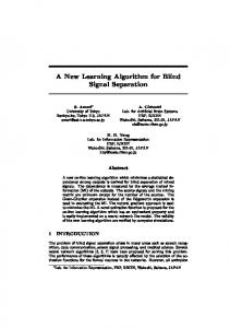
1. Introduction There are several compression formats available for the compression of color images, such as JPEG, JPEG2000 [1], and PTC [2]. Similarly, there are several compression formats for binary text and diagrams: CCIT G4 (fax), JBIG2, and BLC [3]. Those formats are not appropriate for bitmaps that contain a mixture of color images and colored text, such as book covers, catalog pages, flyers, etc. If we try to store such documents with JPEG, for example, the user must make a difficult choice between text readability and poor compression. This is because text and drawings contain very sharp edges, which compress poorly using standard color image compression algorithms. The lack of a unifying format for bitmaps of composite documents led us to develop the SLIm (Segmented Layered Image) encoder. As shown in Fig. 1, SLIm operates by segmenting the image into three components: the background, the foreground, and a binary mask that indicates whether each pixel belongs to the foreground or the background. Text, annotations, and drawings are captured in the binary mask and compressed using our BLC codec [3] (but other bi-level codecs such as CCIT G4 or JBIG2 could be used). The much smoother foreground and background bitmaps are then compressed using our PTC codec [2] (again, other image codecs such as JPEG or JPEG2000 [1] could be used). That way, each codec only sees the kind of data for which it was designed, leading to better compression overall (2× to 10×) than if we used PTC or JPEG on the original bitmap.
Figure 1. Simplified block diagram of the SLIm encoder.
2. The Segmented Layered Image (SLIm) architecture As shown in Fig. 1, SLIm has four basic components: mask computation, foreground/ background layering, texture-layer codecs, and mask codec. In this paper, we concentrate on the mask computation, which is described in detail in Section 3; in this section we give general guidelines as to how to implement the other parts of the codec. Once the mask has been computed, the segmenter separates foreground from background. The decoder combines them according to the mask: a pixel that belongs to the foreground does not need to be encoded in the background, and vice versa. One approach is to use an image codec that uses the mask, such as the masked wavelet coder in [4], to encode each of the foreground and the background images. The masked wavelet coder works well at high bit rates, but has visible artifacts at high compression ratios. Another approach is to assume that an off-the-shelf image codec will be used to encode the entire foreground and background bitmaps, so we fill the “don’t care” masked pixels with values that yield good compression, knowing that they will not be used in the decoder. The problem is then to interpolate the valid pixels in the masked locations in a way that does not introduce sharp edges; the smoother the image in the masked region, the better the compression performance. We propose three different algorithms to solve this problem; they yield about the same compression performance (within 2%), but can vary in speed by as much as a factor of 4×, depending on the amount of code optimization. A. Voronoi: The simplest algorithm is to set the value of each masked pixel to the value of the closest visible pixel. This creates a Voronoi diagram, which has sharp edges, which can be smoothed by a lowpass filter. B. POCS: This approach uses a Projection Onto Convex Sets (POCS) problem. Consider the set U of images that have known values on given (not masked) pixels and arbitrary values on the remaining (masked) pixels. Consider the set V of images that have zero high-frequency coefficients in a Fourier or wavelet transform domain; it can be shown that U and V are both convex sets. Thus, by performing alternate orthogonal projections on each of these sets, one can quickly converge towards an image in the intersection [5]. That image thus has the desired values on the visible pixels, and a smooth interpolation on the masked pixels. This is the approach taken in DjVu [6].
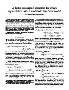
C. Filtering: The third approach consists in running an averaging filter that scans the image from left to right and top to bottom and replace each masked pixels by a linear combination (e.g. the average) of the left and above pixel. Another similar filter is ran in the opposite directions from the bottom right of the image, and a linear combination of the results from both filters is computed, weighted by the distance of the nearest non-masked pixel encountered by the filters. It can be shown that the masked pixels near the visible pixels are a linear interpolation of these pixels, and that the interpolated image gets smoother as a function of the distance to the nearest nonmasked pixel. This is the approach that we used for computing the foreground and background shown in Fig. 2. The diagonal artifacts visible in the masked regions of the foreground and background images are characteristic of this approach. They are the result of the linear combination of the left and above (right and below) pixels of the filters. These artifacts are not visible in the reconstructed image.
Figure 2. Example catalog page. Top left: compressed with JPEG (650 kytes) and SLIm (107 k). Bottom: SLIm components; left to right: Mask (43 k), Foreground (34 k), and ackground (29 k)
Once we have the foreground and background images with one of the methods above, they can be encoded with a standard image encoder (JPEG, JPEG-2000, or PTC). Many additional optimizations can be done, such as compressing these images at different resolution, identifying regions of constant color, etc., but these are not the focus of this paper. The mask is encoded using a binary encoder. To maximize compression, the binary encoder can take advantage of finding similar shapes, such as letters, and build a dictionary of shapes, such as in JBIG2 [7]. Our binary codec is a variation of BLC [3] that also uses a shape dictionary.
3. Mask Separation We want to assign each pixel to be either foreground or background, in order to maximize the combined compression of mask, foreground and background. Assuming the original bitmap has N pixels, there are 2 N possible masks, and of course we cannot search all possible ones. In SLIm we take a greedy approach, making many simplifying assumptions. First, we compute the mask using only a gray level version of the image. This could potentially be harmful, but in practice, text typically has a high contrast in the Y component of YUV (otherwise it would not be easy to read by the human eye). We also assume that the foreground and the background are constant over small regions, and thus we look for a mask that minimizes the variance within those regions, since that closely approximates the choice with maximum compression performance. At this point, we are ignoring the cost of compressing the mask. Further refinements take the size of the mask into account. Let us assume that we are interested in compressing a region consisting in a set S of N pixels, and that F and B are a partition of S (i.e. F ∪ B = S and F ∩ B = ∅ ). If f ( x) is the image value at pixel location x, x ∈ S , the variance of the foreground and background are respectively: vF = ∑ ( f ( x ) − µ F ) 2 , vB = ∑ ( f ( x ) − µ B ) 2 x∈F
x∈B
1 1 f ( x) and µ B = ∑ ∑ f ( x) are respectively the mean of the foreN F x∈F N B x∈B ground and the background, and N F and N B are respectively the number of pixels in the foreground and the background. Note that these variances can also be expressed as:
where µ F =
vF = ∑ f ( x ) 2 − N F µ F 2 , x∈F
vB = ∑ f ( x) 2 − N B µ B 2 x∈B
Our approach is to divide and conquer. Let us partition the image further into 2×2 pixel sub-images. On each 2×2 sub-image, there are only 2 4 = 16 possible masks. This means that on each of these regions, it is possible to find the optimal F and B that minimize E = vF + vB by trying all 16 combinations. It turns out that it is not necessary to try all 16 combinations; the problem is equivalent to a K-means problem with K = 2, and since f (the image) is a scalar function, the values f ( x) can be sorted, yielding a solution that can be computed very efficiently: sort the 4 pixel values (of each 2×2 region), and find which one of the 3 partitions (with respect to the sorting) yields the lowest energy (we can
re-use partial sum in each partition to minimize the number of operations). We now have an “optimal” foreground/background separation for each 2×2 region. This solution, however, has the drawback that every 2×2 sub-region has a distinct foreground and background, which picks up even the slightest pixel noise, resulting in a global mask that looks very much like salt and pepper. Since our goal is to capture text and graphic lines in the mask, this solution alone is inadequate. Thus, the next step consists in combining adjacent regions. Let us label these 2 regions 1 and 2 and their corresponding foreground and background, F1 , B1 and F2 , B2 . When combining these 4 sets, we have in effect 7 distinct possibilities, as shown at the bottom right of Fig. 3; the winning combination is the one which has the lowest resulting energy E = vF + vB . Note that all 7 combination can be tried, or the average in foregrounds and backgrounds can be sorted and we can consider only the partitions which respect the sorting. Furthermore, if each regions keeps the quantities ∑ f ( x) , ∑ f ( x) 2 and N F for the foreground F
and ∑ f ( x) , B
∑
F
f ( x) 2 and N B , all the possible combinations for E can be computed in
B
constant time. After each merges, these quantities must be recomputed, but fortunately, 2 this is also done in constant time. Also note that the sum ∑ f ( x) over all the regions in constant for each partitions, and need not be calculated for the purpose of choosing the optimal partition. Combining adjacent regions can proceed by combining all the horizontally adjacent 2 by 2 regions into 2 by 4 regions, followed by combining all the vertically adjacent 2 by 4 regions into 4 by 4 regions. We then repeat the process with all the 4 by 4 regions until we get 8 by 8 regions and so on until there is only one region left, which is partitioned into foreground and background. Unfortunately, this would lead to merges that put several gray levels into the foreground or into the background, with a potential loss of important details such as text, whenever there are more than two colors in a region. However, whenever two colors are
Figure 3. Left: The mask is computed by first finding the mask on each 2×2 regions (K-means with K = 2). Right: adjacent regions are combined by finding the optimal of seven partitions among the four sets F1, F2, B1, and B2.
merged in either foreground or background, we see a sharp increase of energy (or variance) for that region, since a constant is no longer a good model for this region. So, we choose to not merge adjacent region if the energy E exceeds a certain threshold T, which is determined experimentally. We first merge all of the regions in a bottom-up fashion until only one region is left. We then do a top-down recursive sweep, starting at the largest region, and we recursively split the region if the energy E exceeds T. If E is lower than T for a given region (we are at a leaf of the recursion), we take µ F and µ B for the corresponding region, and for each pixel in the region, we assign them to the foreground if they are larger than ( µ F + µ B ) / 2 and to the background otherwise. The computation has similarity to computing a quad tree, and is illustrated in Fig. 4. We now describe a few important refinements in the mask computation algorithm.
3.1. Non-constant regions Instead of using a constant assumption for foreground and background, one could also assume a polynomial regression. For instance, if the polynomials are planes of an equation α x + β y + µ , the energy would be defined by: vF = vB =
∑ ( f ( x, y ) − α
F
x + β F y + µF )2
∑ ( f ( x, y ) − α
B
x + β B y + µB )2
x , y∈F
x , y∈B
where x, y index the pixel locations, and α F , β F and µ F are scalars that minimize vF and α B , β B and µ B are scalars that minimize vB . Note that α F , β F and µ F can be solved in 2
constant time using the quantities ∑ f ( x, y ) , ∑ f ( x, y )x , ∑ f ( x, y ) y , and ∑ f ( x, y ) . It’s a linear system of 3 unknown and 3 equations. The same applies to α B , β B and µ B . As before the algorithm is bottom-up and minimizes E at each merge. The foregrounds and backgrounds cannot be sorted by average, and therefore all 7 combinations must be tested to find which one minimizes E . To keep doing each tests and merge in constant 2 time, the quantities ∑ f ( x, y ) , ∑ f ( x, y )x , ∑ f ( x, y ) y , ∑ f ( x, y ) and N must be kept for each region for the foreground and the background.
Figure 4. Left: Example synthetic image; the straight lines delimit the leaf regions of the recursion. If K = 0, each leaf contains only two colors. Right: the resulting mask
3.2. Simple regions and speed considerations To improve speed performance, we measure the pixel variance on small regions (we chose 4×4) and if this variance is sufficiently low (using a threshold determined experimentally), we assign all the pixels in this region to be all foreground or all background (with the other set being empty). On relatively clean images, the test succeeds often enough to yield a significant speedup. The number of operations to compute the mask is then close to 2 multiply-adds per pixel (to compute the average and variance of the region). On busy images, every group of 2×2 pixel needs to be sorted (5 tests, or close to 1 op/pixel), average and variance must be computed to test 3 foreground/background separations (close to 6 ops/pixels), the same foreground/background separation is done at lower resolution recursively (about 6/2 + 6/4 + 6/8 + … = 6 ops/pixel), and finally a test for each pixel to determine if the mask is foreground and background. In total, in the worse case, we perform roughly 15 operations per pixels to compute the mask. With the simple region optimization and a threshold that does not affect the quality of the mask, we observed a 3× speedup on typical images, or about 5 operations per pixels.
3.3. Dithering detection Simple regions (region which are pure foreground or pure background) can also be set after the foreground and background have been computed. If the difference between the average foreground and the average background is less than a certain threshold L, which is determined experimentally (a value of L=40 is used for gray level going from 0 to 255), the whole region is set to either foreground or background (depending on whether the average is closer to 0 or to 255). This latter optimization is necessary because it prevents regions with dithering to enter the mask in dithered form. When this happens, the mask does not compress very well and the compression is negatively affected.
3.4. Constant color regions Letters in text are typically of constant color. As a result, compression can be improved by finding the connected components that are good text candidates and have close to constant color. Those connected components are tagged as masked during the compression of foreground and background, and their color is sent separately. At reconstruction, they are pasted back on the reconstructed image. This improves compression significantly on images that are mostly text.
3.5. Dilation The transitions between what we tag as foreground and background often spread over a few pixels in the original image, even around text. This means that the pixel right next to the transition which are used to encode the foreground on one side, or the background on the other, often have high frequencies which are expensive to encode and which can produce ringing. To alleviate this problem, the mask (and its inverse) is eroded by 2 pixels when encoding both the foreground and the background. The pixels around the mask boundary are ignored. The computational cost of a square dilation is slightly more than doing a run-length encoding (we do it in one pass with backtracking).
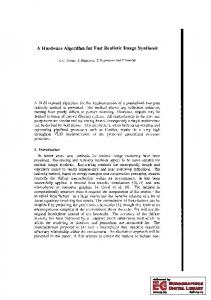
3.6. Block retouching Looking at Fig. 4, we see that the recursive algorithm introduces straight lines inside the horizontal ellipse. This is unavoidable, because the algorithm is not allowing more than two colors inside a foreground or background region, and there are more than two colors in the image. Thus, we need to have several regions. These additional lines have negligible compression costs on the mask because straight horizontal and vertical lines are easily predictable by an entropy encoder with a small context. However, the foreground and background are usually encoded aggressively with large quantization steps, and the artificial mask transitions can introduce visible blocking artifacts (Fig. 5, bottom left). To decrease the effect, we detect the artificial transition with a simple test: If a horizontal or vertical line in the mask is 4 pixels or longer, and the average difference between foreground and background along this line is less than 10 grey levels, then the line is tagged as artificial. We then unmask pixels around that line for both the background and the foreground. Then the same pixels are encoded twice in both the foreground and the background. Still, if the line is artificial, the region around the line is smooth; otherwise another non-artificial pattern would have been picked by the mask. This retouching step increases file size by only 4%, but cleans up the image; see Fig. 5 (bottom middle). Fig. 5 also contains a comparison with DjVu on a comic strip image. On the top row, we see DjVu and its mask, while SLIm is shown on the bottom row. It is immediately obvious that the SLIm mask picks up a lot more information that the DjVu mask, both for text and on people. The SLIm mask is symmetric in the sense that it treats foreground and background identically. This is an advantage for some images, and in particular for comic strips: the faces in the DjVu image are more fuzzy than in the SLIm image. Note that without retouching, the SLIm image would be inferior to DjVu. The cost of block
Figure 5. Mask separation and block retouching. Top left: DjVu reconstruction; right: DjVu mask. Bottom left: SLIm reconstruction, no retouching; middle: SLIm reconstruction with retouching; right: SLIm mask.
retouching is comparable to run-length encoding: detection of area that needs to be retouched requires looking at all the pixel, but the areas needing retouching are very rare.
3.7. Sensitivity to scale Most parameters used for mask separation are not sensitive to image scaling. For instance, the energy threshold used to merge foreground and background yields slightly larger or smaller merged region sizes, if the image is scaled up or down. This only adds or removes a few vertical and horizontal lines to the mask, and so size of the mask doesn’t change substantially. An additional cost would come from block retouching in foreground and background, but would typically amount to just a few percent change (depending on the amount of compression for the foreground and background). Scaling also affects dithering detection and dilation, but we have not yet devoted efforts to make them scale independent; we have adjusted the corresponding parameters for 300dpi scans.
4. Final Comparisons The basic idea of encoding a composite bitmap by separating it into foreground, background and mask layers is not new. For example, it has been studied at the ITU-T under the denomination of mixed raster content (MRC) [4]. Here we compared the performance of SLIm with three other MRC formats: DjVu [6] for LizardTech, TIFF-FX from ScanSoft, and DigiPaper from Xerox. In Fig. 6 we have a typical example that illustrates the need for composite document image compression technology. Note that with JPEG there is significant ringing around text, even though the file size is 2× that of SLIm. To avoid such ringing, the JPEG file size would have to be increased to 4× that of SLIm. On images containing mostly text, SLIm and DjVu files can be an order of magnitude smaller than JPEG. We see that DjVu leads to about 35% better compression, but with a bit more blurriness in texture areas.
Conclusion We have designed a mask separation algorithm for compression of images. Unlike approaches such as DjVu and TIFF-FX, it yields a symmetric separation of foreground and background. This yields better compression for certain images, in particular comic books. We built an end-to-end system, named SLIm, to test its overall performance and found that it compares well with the others, although DjVu files are typically 35% smaller. The main advantages of the mask separation in SLIm are its algorithm simplicity, dependency on just a few parameters, symmetry, and speed (less than 10 operations per pixel). The algorithm also has promising refinements such as using linear approximation of the foreground and background instead of constants when computing the mask.
References [1] D. S. Taubman and M. W. Marcellin. JPEG2000 Image Compression, Fundamentals, Standards, and Practice. Boston, MA: Kluwer, 2002. [2] H. S. Malvar, “Fast progressive image coding without wavelets,” Proc. Data Compression Conf., Snowbird, UT, pp. 243–252, Mar. 2000. [3] H. S. Malvar, “Fast adaptive encoder for bi-level images,” Proc. Data Compression Conf., Snowbird, UT, pp. 253–262, Mar. 2001.
[4] P. Y. Simard and H. S. Malvar, “A wavelet coder for masked images,” Proc. Data Compression Conf., Snowbird, UT, pp. 93–102, Mar. 2001. [5] D. C. Youla and H. Webb, “Image restoration by the method of convex projection: Part 1 – theory,” IEEE Trans. Medical Imaging, vol. MI–1, pp. 81–84. [6] L. Bottou, P. Haffner, P. Howard, P. Simard, Y. Bengio, and Y. LeCun, “High quality document image compression with DjVu,” J. Electronic Imaging, 1998. [7] P. G. Howard, F. Kossentinit, B. Martins, S. Forchhammer, and W. J. Rucklidge, “The emerging JBIG2 standard,” IEEE Trans. Circuits and Syst. for Video Technology, vol. 8, pp. 838–848, 1998.
Figure 6. Top: example of a typical composite document. Bottom: zoomed regions of decoded images using four codecs: JPEG (200 kbytes), TIFF-FX (135 k), SLIm (100 k), DjVu (65 k).