This article has been accepted for publication in a future issue of this journal, but has not been fully edited. Content may change prior to final publication. Citation information: DOI 10.1109/JPHOT.2017.2684823, IEEE Photonics Journal
A Reconfigurable Optical Logic Gate with up to 25 Logic Functions Based on Polarization Modulation with Direct Detection Xianfeng Tang, Zhongqin Fang, Yaxue Zhai, Xiangsen Jiao, Na Gao, Xiaoguang Zhang, Senior Member, IEEE, Lixia Xi, Jianping Li and Wenbo Zhang Abstract—We propose and investigate a new scheme to
realize optical logic gates using polarization addition with direct detection. Two polarizations of an optical signal are modulated respectively by independent binary inputs to represent four different states, while direct detection is used to map the four states to the corresponding binary output. Up to 25 logic gates including all the basic logic gates can be implemented by adjusting bias voltages of the two modulators, peak-peak voltages of the driving signals and the rotation angle between the two polarizations. A modified Poincare sphere and a simplified two-dimension description are developed to illustrate the principle of proposed scheme. Experiments are successfully carried out to realize all of the 6 basic logic gates at 1 Gb/s. Influences on the performance of logic gates are also studied by considering some key factors such as extinction ratio of Mach-Zehnder modulator, input power and rotation angle deviation. Index Terms—Optical logic gates, polarization, direct detection
I. INTRODUCTION As the fundamental elements of optical signal processing, optical logic gates are essential for optical computing as well as optical networking in addressing, switching, header recognition, data encoding, regeneration, parity checking and network coding [1-7]. Thus, the implementations of different optical logic gate functions have attracted a lot of interests in recent years. Recently, several schemes for realizing optical logic gates have been proposed. These schemes can be roughly divided into two categories: schemes based on nonlinear optics and those based on modulators. In the former schemes, semiconductor optical amplifier (SOA) [8, 9], highly nonlinear fiber ( HNLF) [10, 11], silicon nanowire [12] and periodically poled lithium niobate (PPLN) [13] are widely used. However, HNLF is hard for photonic integration [14], SOA is short in speed limit and latency [15], and PPLN needs precise This paper is submitted for review on Feb. 14th, 2017. The work was supported by the National Natural Science Foundation of China (Grant No.61571057, Projects No.61501213), Fund of State Key Laboratory of Information Photonics and Optical Communications (Beijing University of Posts and Telecommunications), P. R. China (No. IPOC2016ZT12), the Ph.D Programs Foundation of Ministry of Education of China (20134401120007), and the Open Fund of the Guangdong Provincial Key Laboratory of Optical Fiber Sensing and Communications (Jinan University).
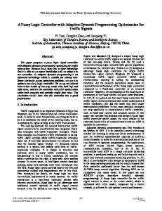
temperature control [16]. In the latter approaches, various modulators and interferometers are adopted to realize the desired logic funtions by manipulating the intensity and/or the phase of the input signals [17, 18]. In this paper, we propose a new scheme based on vector addition of two signals with different states of polarization, which can be easily reconfigured to implement up to 25 types of optical logic gates including all the basic functions of logic gates. Different from the existing methods using modulators, polarizations of the optical signals, serving as an additional degree of freedom, are utilized in our method while direct detection (DD) is adopted at the output port. In the scheme, by setting the power of the input signals, the bias levels of the two modulators, and the rotation angle between the two polarizations, different optical logic gates can be realized using the same set of hardware. A modified Poincare sphere and a simplified two-dimension description are developed to illustrate the principle of proposed scheme. 6 basic logic gates (OR, NOR, AND, NAND, XOR, and NOR) are realized in the experiments at 1 Gb/s. Performances of the logic gates are evluated with different input power, extinction ratio (ER) of Mach-Zehnder modulator (MZM) and rotation angle deviation. The processing speed of the proposed optical logic gates is mainly governed by the bandwidth of modulators and photodetectors, which is now commercially available at up to 100 GHz [19, 20]. II. PRINCIPLE A. Mathematical description The system diagram of the proposed scheme to realize optical logic gates is illustrated in Fig. 1. The optical logic gates consist of a continuous wave (CW) laser, two parallel MZMs driven by two input binary data, two polarization rotators and a photodetector (PD). By setting voltages of the input data (Vp1 and Vp2), bias voltages of the two parallel MZMs (Vb1 and Vb2) and angle between the polarizations of the two arms (Vp3 and Vp4), different logic gates are implemented.
Xianfeng Tang, Zhongqin Fang, Yaxue Zhai, Xiangsen Jiao, Na Gao, Xiaoguang Zhang, Lixia Xi, and Wenbo Zhang are with State Key laboratory of Information Photonics and Optical Communications, Beijing University of Posts and Telecommunications, 10 Xitucheng Rd., Beijing, 100876, P. R. China (e-mail:
[email protected]). Jianping Li is with Institute of Photonics Technology, Jinan University, Guangzhou 510632, P. R. China.
1943-0655 (c) 2016 IEEE. Translations and content mining are permitted for academic research only. Personal use is also permitted, but republication/redistribution requires IEEE permission. See http://www.ieee.org/publications_standards/publications/rights/index.html for more information.
This article has been accepted for publication in a future issue of this journal, but has not been fully edited. Content may change prior to final publication. Citation information: DOI 10.1109/JPHOT.2017.2684823, IEEE Photonics Journal
1011000
Vp2
Vb2
MZM_I
MZM_2
CW Laser
Vb4
Polarization Rotator
MZM_1
PDPD
CW Laser
0101101
Vp1
Vb1
Vb3
Fig. 1: System schematic diagram of the proposed optical logic gate.
Suppose that the input light emitted from the CW laser is completely polarized which can be described by a Jones Vector: E (1) | Ein x , EY where Ex and Ey are respectively the x-polarization and ypolarization components of the complex amplitude of the signal electric field
ax cos sin || (Vin1 (t ) Vbias1 ) j cos 10 sin cos 2V by e ax 2 cos (Vin 2 (t ) Vbias 2 ) j || 2 V by e
I ||| Er o t1 | Er o t 2 ||2
| Ein . Here, a ket vector | Ein is used to
represent the polarized electric field. Meanwhile, a bra vector
Ein | can also be used to describe the same polarization vector as the dual of the ket vector. The bra vector is the adjoint ( † ), or complex-conjugate transpose, of the corresponding ket vector: (2) Ein | (| Ein )† Ex EY . In this way, the intensity of the light can be derived by calculating the inner productor of the vector and is determined by multiplying the bra representation representation
intensity and phase. After modulation by the input signal, polarization of the light on each branch will be rotated by different angles. As the function of logic gate is related with the inclined angle between the polarizations of the two branches, the rotation angle of the polarization of the light on the lower branch is set to be zero for simplicity. After state of polarization being rotated by an angle of ξ, light on the upper branch can be expressed as: cos sin (6) | Er o t | Emod sin cos From the expression, we can see that norm of the rotated electrical field is the same with the one before polarization rotation, which means that intensity of light will keep unchanged during the process of polarization rotation. After vector addition and direct detection, the output will be derived:
| Ein with its ket
Ein | : || Ein ||2 Ein | Ein ,
(3)
where || || is the norm of the vector. Since the entries of the vector are complex, we can further write the vector with the form of magnitude and phase: ax e j x ax j , | E in e b e j y by e j y
(4)
where ax and ay are magnitudes of x-polarization and ypolarization components respectively, is the common phase and is the phase difference between the two polarization components. As signal modulation and polarization states are both used in the proposed logic gates, we will keep the absolute phase and the intensity items in the expression of Jones vector. The incoming polarized light is split into two equal parts which are modulated in two MZMs by the input binary signals respectively. When MZM is operated in the push-pull mode, light after modulation is obtained: V j bias ax 1 | Emod ( /20) cos (Vin (t ) Vbias ) e 2V j e j , (5) 10 2V by e
is the insert loss of MZM, Vin is the driving voltage of signal, Vbias is the bias voltage and V is the half-wave voltage. where
From the expression, we can see that both the intensity and the common phase of the electric field are changed by bias voltage and input driving signal. In this sense, input signal is loaded onto the optical carrier and represented by the corresponding
1
( /20)
(7) For a typical 2x1 logic gate (two inputs and one output), the function is to map the four combinations of the two input signals ((0, 0), (0, 1), (1, 0), (1, 1)) to the desired two output states (0, or 1). Here, two input signals are represented by intensity and phase of two beams of light with different polarizations. By controlling the five parameters (Vin1, Vbias1, Vin2, Vbias2 and ξ) in (7), we map the four input combinations to the corresponding output states. B. Geometrical illustration of the principle To illustrate the principles described above in stokes space, we modified the Poincare sphere (M sphere) to adapt to the mechanism of realizing logic gates. Since the Poincare sphere is normalized and the Stokes parameters S1, S2, S3 are timeaveraged, changes in intensity and absolute phase cannot be described on the Poincare sphere. Here, we use the radius of sphere to represent the intensity of light. Furthermore, we modified the expression of Stokes parameters (M parameters) S1, S2, S3 to combine the phase of modulation and the state of polarization: S1 S0 cos 2 cos 2 0 S2 S0 cos 2 sin 2 S S sin 2 4 4 3 0 S1 S0 cos 2 cos 0 when modulation phase 0, S2 S0 cos 2 sin S S sin 2 4 4 3 0 S1 S0 cos(2 ) cos( ) 0 when modulation phase , S 2 S0 cos(2 ) sin( ) S3 S0 sin(2 ) 4 4
(8) where S0 represents total intensity of the light, (0 ) specifies the orientation of the polarization ellipse and
(
characterizes the ellipticity and the sense of )
4 4 the polarization ellipse. By modifying the polar angle from 2
1943-0655 (c) 2016 IEEE. Translations and content mining are permitted for academic research only. Personal use is also permitted, but republication/redistribution requires IEEE permission. See http://www.ieee.org/publications_standards/publications/rights/index.html for more information.
This article has been accepted for publication in a future issue of this journal, but has not been fully edited. Content may change prior to final publication. Citation information: DOI 10.1109/JPHOT.2017.2684823, IEEE Photonics Journal
to while keeping definition domain unchanged, half sphere (eastern or western sphere) can realize complete representation of polarization. Eastern sphere with polar angle [0, ] is used to represent light with modulation phase of 0, while western sphere with polar angle [ , 2 ] to represent light with modulation phase of π. S3
S3
(1, 1) (0, 1)
ξ
(1, 0)
(0, 0) (1, 0)
S2
ξ
S1
(0, 1)
S2 (0, 0) (1, 1)
S1
(a)
(b)
Fig. 2: Illustrations of “AND” logic on M sphere with input light (a) elliptically polarized and (b) linearly polarized, respectively.
Fig. 2. (a) gives the illustration of “AND” logic on M sphere with input light elliptically polarized. MZM on the lower arm is biased at Null point and driven by the signal with peak-to-peak voltage of 2Vπ, while MZM on the upper arm biased at +Quad point and driven by Vpp of Vπ. Polarization of the light on the upper arm is rotated by an angle of 600. Through vector addition three combinations ((1, 0), (0, 1), (0, 0)) are mapped to points on the same sphere with the same intensity, while (1, 1) is mapped onto the sphere with higher intensity. After direct detection, two levels of voltages are obtained which are exact the expected results. For linearly polarized input light, addition of polarization obeys the rule of vector addition in stokes space as shown in Fig. 2. (b). Orientation angle_upper
vector addition of polarizations for four combinations, four points are derived distributing on two circles shown in Fig. 3 (b). C. Reconfiguration of logic functions (a) 6 basic logic functions Based on the same principle as “AND” logic gate, the other five basic logic gates can also be realized by adjusting the bias voltages of the two MZMs, the peak-to-peak voltages of the signals and the polarization rotation angle between two arms. Tab. 1 shows the typical configurations of six basic logic gates. In addition, Fig. 4 gives the illustrations of these six logic gates. Four combinations of input signals (the triangular points) are represented by four states (the circular points) distributing on two circles which are mapped to corresponding 0 or 1 output voltage after direct detection. From the figure, theoretical values of ER can be derived for different logic gates and these values vary greatly due to the different configurations. Tab. 1: Configurations of six basic logic gates Bias of lower MZM Null point Null point +Quad point Null point +Quad point Null point
Gate type
AND
OR XOR XNOR
0.8Vπ
NAND
(1, 1)
0
1
2Vπ
Vπ
450
2 Vπ
Vπ
1200
Vπ
Vπ
900<ξ≤1800
2Vπ
2Vπ
1800
Vπ
Vπ
2Vπ
2Vπ
Vπ
Vπ
Vπ
Vπ
00≤ξ<900 104.48 60
0
0
90°<ξ≤ 180°
(0,1)
(0,0)
ξ (0, 1)
(0, 0)
Orientation angle_lower
ξ 0
(0,1)
1 ξ
ξ
Orientation
1 (1,0) angle_lower
0
(1,1)
(1,1)
1
1
0
600
ξ =120°
(1,1)
(0,1)
Orientation angle_lower
Vpp2
angle_upper
(1, 0)
1 ξ
Vpp1
0.8Vπ
ξ =60° Orientation
(1, 1)
Polarization rotation angle
0.8Vπ
0.8Vπ
NOR
Orientation angle_upper
Bias of upper MZM +Quad point +Quad point +Quad point Null point +Quad point Null point
(0,0) 0
1
0
1 (1,0)
0 (0,0) (a) AND
ξ=60°
ξ=60°
ξ=60°
ξ=104.48°
0°≤ ξ<90°
(a)
(1,0)
(c) XOR
(b) OR
(b)
Fig. 3: Two-dimension illustration of “AND” logic. (a) vector addition for input combination of (1, 1); (b) vector addition for four input combinations. Triangular points: signals after modulation on each arm; circular points: signals after coupling of the two polarizations
To make this clearer, we can simplify the description to twodimension as shown in Fig. 3. It can be demonstrated that the rule of vector addition is obeyed in the orientation angular coordinates as in the Jones space. The horizontal axis represents the intensity and phase modulation of input completely polarized (linearly or elliptically) light on the lower arm. Modulation on the upper arm is represented on the rotated polarization. For “AND” logic, 0 and 1 inputs are represented by the triangular points on each polarization at the required bias points. Vector additions of polarizations are conducted for different input combinations. For instance, when two inputs are 1 and 1, blue circular point is obtained shown in Fig. 3 (a). After
(0,1)
1
(1,1)
(0,1)
0 (0,0)
1 0
(1,0)
(d) XNOR
1
(0,1)
(1,1)
ξ 1
0
(1,1)
1
ξ
ξ
1
0 0
(0,0)
0
(e) NAND
(1,0)
(0,0)
(1,0)
(f) NOR
Fig. 4: Configurations and illustrations of AND (a), OR (b), XOR (c), XNOR (d), NAND (e) and NOR (f) gates
(b) 19 advanced logic gates As seen in Fig. 5, phase of the output signal will be inverted by changing the bias point of MZM from Vbias to (Vbias+Vπ). This can also be observed from eq. (5): a phase of π will be added to the output signal of MZM when adding Vπ to Vbias. A NOT gate will be realized by simply changing the bias point from +Quad
1943-0655 (c) 2016 IEEE. Translations and content mining are permitted for academic research only. Personal use is also permitted, but republication/redistribution requires IEEE permission. See http://www.ieee.org/publications_standards/publications/rights/index.html for more information.
This article has been accepted for publication in a future issue of this journal, but has not been fully edited. Content may change prior to final publication. Citation information: DOI 10.1109/JPHOT.2017.2684823, IEEE Photonics Journal
to –Quad. Besides, a series of advanced logic gates can be constructed based on this property, such as A & B . Output Power Input Power
MZM Transmission Curve
1 0 1
0 1
0
1 0
Light
VbiasVπ
1
0
0
1 0
1 0
1
Data
Voltage
VBias +Vπ 1
1
0
1
Data
Fig. 5: Illustration of phase inversion of the output signal by changing the bias voltage from Vbias to (Vbias+Vπ)
Hence, the proposed structure can be reconfigured to realize 24 logic gates with form of ( Aor A)(&, , , , , )( BorB) as well as NOT gate. Moreover, the extended logic gates have similar ER values with the original logic gate based on the above principle.
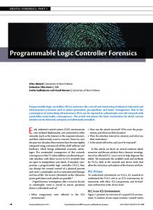
the theoretical analyses (for AND gate, the theoretical ER value is 6.99 dB when rotation angle is 450). We also recorded the output states of polarization (SOPs) on normal Poincare sphere and output optical powers of four inputsignal combinations when operating at the function of OR gate. Fig. 9(a) gives the results when the input light is linearly polarized and Fig. 9(b) shows the results for elliptically polarized light. From the results, we can see that the output optical powers are almost the same for input signals of (1, 0), (0, 1), and (1, 1) and the value is much higher than the one of (0, 0) when configured as OR gate. Thus this function works both for linearly polarized light and elliptically polarized light. We can also see that the measured SOP of output light polarization is consistent with the one analyzed in the principle. signal1 10001111001111100110110001010100100011100011011010
signal2 01011100001100000110010011101010110111000111001001
III. EXPERIMENTAL RESULTS AND PERFORMANCE
AND 00001100001100000110010001000000100011000011001000
150μw/div
OR 11011111001111100110110011111110110111100111011011
100μw/div
XOR 11010011000011100000100010111110010100100100010011
100μw/div
ANALYSES
1 Gbit/s Vp1
Vb1 vertical Y
MZM-1
PC1
DC GND AC
V/div
XNOR 00101100111100011111011101000001101011011011101100
150μw/div
NAND 11110011110011111001101110111111011100111100110111
50μw/div
trigger
ECL
timebase
MZM-2
PPG
X
PC2
OSC 1 Gbit/s Vp2
s/div
DC GND AC
Vb2
Fig. 6: Experimental setup of the proposed reconfigurable optical logic gates
Experiments are carried out to verify our proposed scheme to realize reconfigurable optical logic gates and the setup is shown in Fig. 6 . A tunable external cavity (ECL) laser with line-width smaller than 100 kHz is used as the light source. The output power of ECL is set at 5 dBm. Two MZM modulators with insert loss of 5 dB are driven by the two input binary data with required Vpp as shown in Tab. 1. Two polarization controllers (PC) are used to rotate the azimuth angle of the two polarized lights. Bias voltages of the two MZMs and the polarization rotation angle are also selected as required. Two binary data are generated using a pulse pattern generator (PPG) at 1 Gb/s due to the limitation in the lab. A wideband Oscilloscope (OSC) is used to detect the light and record the waveform. Fig. 7 shows temporal waveforms of the input signals and output signals of the logic gates. From the results, we can see that the expected logic gates are successfully realized using our proposed scheme. In the experiments, output of the logic gate is not stable as it is polarization-sensitive. However, stability can be improved when these components are integrated together in the future. Performances of logic gates are further studied in the simulation at 10 Gb/s. Setup of the simulation is similar to that of the experiment and parameters used in the simulation are summarized in Tab. 2. Fig. 8 shows temporal waveforms and eye diagrams of the input signals and output signals of the logic gates. Measured ERs of the output signals are all higher than 6.01 dB for these six gates. These results are in accordance with
NOR 00100000110000011001001100000001001000011000100100
100μw/div
Fig. 7: Temporal waveforms of the input signals and output signals of the logic gates in the experiments at 1Gb/s. 0101101110010110111001011011100101101110
Signal 1
Signal 2
1011000101101100010110110001011011000101
AND
0001000100000100010000010001000001000100
ER=6.87dB
OR
1111101111111110111111111011111111101111
ER=20.40dB
XOR
1110101011111010101111101010111110101011
ER=31.55dB
XNOR
0001010100000101010000010101000001010100
ER=39.76dB
NAND
1110111011111011101111101110111110111011
NOR
0000010000000001000000000100000000010000
ER=6.37dB
ER=6.01dB
Fig. 8: Temporal waveforms and eye diagrams of the input signals and output signals of the logic gates in the simulations at 10 Gb/s.
1943-0655 (c) 2016 IEEE. Translations and content mining are permitted for academic research only. Personal use is also permitted, but republication/redistribution requires IEEE permission. See http://www.ieee.org/publications_standards/publications/rights/index.html for more information.
This article has been accepted for publication in a future issue of this journal, but has not been fully edited. Content may change prior to final publication. Citation information: DOI 10.1109/JPHOT.2017.2684823, IEEE Photonics Journal
(a) Linearly polarized light Lower arm
(300, 00)
(b) Elliptically polarized light
Upper arm
(900, 00)
11
(-300, 00) 3.13mW
10
(-89.750, -50) 3.16mW
Lower arm
(300, 300)
01
(30.250, 50) 3.16mW
00
(-300, 00) 0.03mW
Upper arm
(900, 300)
11
angle. Eye opening factor can be the suitable quality metric to evaluate this influence. Eye opening factor gets the maximum value when the rotation angle is exactly the one required, while the value will fall dramatically when the rotation angle deviates from the standard angle. We can also see from the figure that eye diagram will contain three levels when rotation angle deviates as analyzed above.
01
(30.070, 300) 2.82mW
(-36.70, 300) 2.56mW
10
(-89.750, 300) 2.69mW
00
(-300, 300) 0.03mW
Fig. 9: States of polarization (SOPs) and optical powers of four input-signal combinations when operating at the function of OR for (a) linearly polarized light with azimuth and ellipticity of (300, 00) and (b) elliptically polarized light of (300, 300).
From the principle and system setup, we can see that performance of the logic gate is influenced by a lot of factors including input optical power, noise of devices, ER of MZM, bias points, polarization rotation angle, etc. Analyses are conducted on the performance of OR gate under the influence of some key factors. As a main quality metric to evaluate the performance of optical logic gate, ER of the output signal is measured when changing the ER of MZM at different input powers. From the results shown in Fig. 10, we can see that output ER is becoming larger as ER of MZM increases, and the value changes little when ER of MZM increases to 40 dB and higher. Saturation value of output ER increases with the increase of input power. However, output ER is influenced little by the input power when ER of MZM is small.
Fig. 11: Measured eye opening factor vs. polarization rotation angle and some selected eye diagrams.
IV. CONCLUSIONS We propose a new scheme for realizing various optical logic gate functions based on superposition of polarization modulation. Amplitude and phase on two polarizations are used to generate the required four input states of the logic gates. Direct detection with a photo detector is adopted to generate the required two output states. This scheme is reconfigurable to implement 25 logic functions including all the basic logic gates with the same structure and has the potential to reach very high processing speed depending on the bandwidth of modulator and photo detector. Experiments are successfully carried out to realize six basic logic gates at 1 Gb/s. Performances are also studied in the simulations at 10 Gb/s. Extinction ratios of the output signals are higher than 6.01 dB. Output ER will increase and become saturated as the ER of MZM increases to 40dB and higher. The saturated value is dependent on the input power. Output eye opening factor is greatly influenced by the deviation of polarization rotation angle.
REFERENCES [1]
[2] Fig. 10: Extinction ratio of OR logic gate vs extinction ratio of MZM at different input powers.
We further investigated the influence of rotation angle deviation as shown in Fig. 11. When rotation angle is not the angle required in Tab. 1, signals of different input combinations will distribute on three circles after vector addition of two polarizations. In this way, two high levels will exist in the eye diagram and these two levels will separate wider from one another as the rotation angle deviate more from the required
[3]
[4]
[5]
M. Saruwatari, "All-optical signal processing for terabit/second optical transmission," IEEE Journal of Selected Topics in Quantum Electronics, vol. 6, pp. 1363-1374, Nov-Dec 2000. K. E. Stubkjaer, "Semiconductor optical amplifier-based all-optical gates for high-speed optical processing," IEEE Journal of Selected Topics in Quantum Electronics, vol. 6, pp. 1428-1435, 2000. A. Bogoni, X. Wu, Z. Bakhtiari, S. Nuccio, and A. E. Willner, "640 Gb/s photonic logic gates," Opt. Lett., vol. 35, no. 23, pp. 3955–3957, Dec. 2010. Y. A. Zaghloul, A. R. M. Zaghloul, and A. Adibi, "Passive all-optical polarization switch, binary logic gates, and digital processor," Opt. Express 19, 20332-20346, 2011. J. Dong, X. Zhang, S. Fu, J. Xu, P. Shum and D. Huang, "Ultrafast AllOptical Signal Processing Based on Single Semiconductor Optical
1943-0655 (c) 2016 IEEE. Translations and content mining are permitted for academic research only. Personal use is also permitted, but republication/redistribution requires IEEE permission. See http://www.ieee.org/publications_standards/publications/rights/index.html for more information.
This article has been accepted for publication in a future issue of this journal, but has not been fully edited. Content may change prior to final publication. Citation information: DOI 10.1109/JPHOT.2017.2684823, IEEE Photonics Journal
[6]
[7]
[8]
[9]
[10]
[11]
[12]
[13]
[14]
[15] [16]
[17]
[18]
[19]
[20]
Amplifier and Optical Filtering," in IEEE Journal of Selected Topics in Quantum Electronics, vol. 14, no. 3, pp. 770-778, May-June 2008. J. Qin, G. W. Lu, T. Sakamoto, K. Akahane, N. Yamamoto, D. S. Wang, et al., "Simultaneous multichannel wavelength multicasting and XOR logic gate multicasting for three DPSK signals based on four-wave mixing in quantum-dot semiconductor optical amplifier," Optics Express, vol. 22, pp. 29413-29423, Dec 2014. Joo-Youp Kim, Jeung-Mo Kang, Tae-Young Kim and Sang-Kook Han, "All-optical multiple logic gates with XOR, NOR, OR, and NAND functions using parallel SOA-MZI structures: theory and experiment," in Journal of Lightwave Technology, vol. 24, no. 9, pp. 3392-3399, Sept. 2006. Jae Hun Kim, Young Min Jhon, Young Tae Byun, Seok Lee, Deok Ha Woo and Sun Ho Kim, "All-optical XOR gate using semiconductor optical amplifiers without additional input beam," in IEEE Photonics Technology Letters, vol. 14, no. 10, pp. 1436-1438, Oct. 2002. Jun Qin, et.al., "Simultaneous multichannel wavelength multicasting and XOR logic gate multicasting for three DPSK signals based on four-wave mixing in quantum-dot semiconductor optical amplifier," Opt. Express 22, 29413-29423 (2014). Changyuan Yu, L. Christen, Ting Luo, Yan Wang, Zhongqi Pan, LianShan Yan, A. E. Willner, "All-optical XOR gate using polarization rotation in single highly nonlinear fiber," in IEEE Photonics Technology Letters, vol. 17, no. 6, pp. 1232-1234, June 2005. J. Qiu, K. Sun, M. Rochette, and L. R. Chen, "Reconfigurable all optical multi-logic gate (XOR, AND, and, OR) based on cross-phase modulation in a highly nonlinear fiber," IEEE Photon. Technol. Lett., vol. 22, no. 16, pp. 1199–1201, Aug. 2010. Zuoshan Yin et al., "All-Optical Logic Gate for XOR Operation Between 40-Gbaud QPSK Tributaries in an Ultra-Short Silicon Nanowire," in IEEE Photonics Journal, vol. 6, no. 3, pp. 1-7, June 2014. J. Wang, J. Sun, X. Zhang, D. Huang, and M. M. Fejer, "Ultrafast alloptical three-input Boolean XOR operation for differential phase-shift keying signals using periodically poled lithium niobate," Opt. Lett., vol. 33, no. 13, pp. 1419–1421, Jul. 2008. J. Wang et al., “High speed addition/subtraction/complement/doubling of quaternary numbers using optical nonlinearities and DQPSK signals,” Opt. Lett., vol. 37, no. 7, pp. 1139–1141, Apr. 2012. D. Kong et al., "All-optical XOR gates for QPSK signal based optical networks," Electron. Lett., vol. 49, no. 7, pp. 486–488, Mar. 2013. E. Lazzeri, A. Malacarne, G. Serafino, and A. Bogoni, "Optical XOR for error detection and coding of QPSK I and Q components in PPLN waveguide," IEEE Photon. Technol. Lett., vol. 24, no. 24, pp. 2258– 2261, Dec. 2012. C. Reis, T. Chattopadhyay, P. Andre, and A. Teixeira, "Single MachZehnder interferometer based optical Boolean logic gates," Applied Optics, vol. 51, pp. 8693-8701, Dec 20 2012. E. S. Awad, P. Cho, and J. Goldhar, "High-speed all-optical AND gate using nonlinear transmission of electroabsorption modulator," IEEE Photonics Technology Letters, vol. 13, pp. 472-474, 2001. L. Alloatti, R. Palmer, S. Diebold, K. P. Pahl, B. Chen, R. Dinu, M. Fournier, J.-M. Fedeli, T. Zwick, W. Freude, C. Koos, and J. Leuthold, "100 GHz silicon-organic hybrid modulator," Light Sci Appl, vol. 3, p. e173, 2014. [Online]. https://www.finisar.com/optical-components/xpdv412xr.
1943-0655 (c) 2016 IEEE. Translations and content mining are permitted for academic research only. Personal use is also permitted, but republication/redistribution requires IEEE permission. See http://www.ieee.org/publications_standards/publications/rights/index.html for more information.