Active Flux Based Motion-Sensorless Vector Control of DC-Excited Synchronous Machines Ion Boldea
Georghe D. Andreescu
Fellow, IEEE Dept. of Electrical Engineering University Polit. of Timisoara, 2 Vasile Parvan Blvd, Timisoara, ROMANIA
[email protected]
Senior Member, IEEE Department of Automation and Applied Informatics, University Politehnica of Timisoara, 2 Vasile Parvan Blvd., Timisoara, ROMANIA
[email protected]
Abstract—This paper introduces a novel, active flux based, motion-sensorless vector control system for dc-excited synchronous motor, suitable for wide speed range applications. The active flux vector, defined as the torque producing flux, is aligned always along the rotor d axis and renders the machine model as with nonsalinent poles magnetic saturation. This vector is obtained from the estimated stator-flux vector minus Lqis vector, via a combined current-voltage model stator-flux observer, and through Lq(im) depending on the total magnetization current. This way, the rotor position and speed estimation is simplified and wide speed range control is feasible. The paper introduces all components of the proposed system including a novel commissioning procedure for magnetization curves identification and a novel method for initial rotor position estimation. Details of control system implementation on DSP controller test platform and plenty of experimental test results for a traction system using dc-excited synchronous motor with 80 Vdc battery are presented. The test results fully validated the proposed solutions and show high performance starting from 15 rpm with heavy load disturbance rejection and rather quick torque response. Index Terms—Flux observers, initial rotor position, magnetic saturation, synchronous motor drives, sensorless control, variable speed drives.
I. INTRODUCTION In wide constant-power speed range drives, the need for overall initial costs, dominated by PWM converter costs, tends to favor the dc-excited synchronous machine (SM). The main reason is the possibility to magnetize the machine from the rotor in dc, via a dc-dc converter with 5% peak power rating and thus, save up to a net 25% of PWM inverter peak kVA and costs. The lower the ac link voltage, the more substantial is the cost reduction, since the PWM inverter/ machine costs is increased. The possibilities to operate at unity power factor, or maximum efficiency through adequate field current control, are also assets of this solution. Finally, the field current reduction in a low magnetic saliency rotor SM produces a large flux weakening (constant power) speed range. The price to pay is the presence and costs of mechanical brushes, which, however, have to transfer to the rotor only up to 5% of the machine rated power.
978-1-4244-2893-9/09/$25.00 ©2009 IEEE
Claudio Rossi Member, IEEE Alessio Pilati Domenico Casadei Senior Member, IEEE Dept. of Electrical Engineering, University of Bologna, Viale Risorgimento 2, 40138 Bologna, ITALY
[email protected]
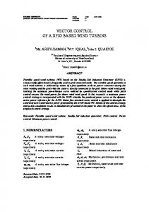
Vector control of a dc-excited SM drives has been applied after 1970 in cement rolling mills and icebreakers with direct drives up to 10 MW and 5.5 Hz [1-4]. Interest in the vector control of dc-excited SM drives was reviewed recently [5] for automotive applications at low-medium power level, together with direct torque and flux control [6-7]. The main reason is, again, large constant power speed range for minimum inverter peak kVA [8-9]. In all these cases, to the best of our knowledge, a rotor position sensor was used for position feedback. While the cost of such position sensor in a medium or large power drive is not prohibitive, its reliability is, and the collateral money loss due to production stoppage for position sensor repair or replacement is the problem. This is the main reason why in this paper a wide speed range motion-sensorless control system for dc-excited SM drives via vector control is introduced and documented. Because the rotor magnetic saliency of a salient pole DCexcited SM machine (such as shown in Fig.1) is small or even absent, and strongly dependent of magnetic saturation level [10], all signal injection of fundamental model magneticsaliency based rotor position & speed observers, so similar with IMs and PMSMs [11-13] have been disregarded. In the paper use is made of the so called “active flux” concept [14], which models a salient-pole rotor ac machine by a nonsalient
2496
b
q d
θer/2 a
c Fig. 1 Four pole DC-excited synchronous machine
pole equivalent model. For the dc-excited SM, the active flux vector is aligned to the rotor position and thus, the rotor position and speed observation becomes a notably simpler task. The paper is organized as follows: Section II - active flux model of SM; Section III - state observer with active flux observer, rotor position and speed estimator; Section IV magnetic saturation model and its identification; Section V initial rotor position estimation; Section VI - motionsensorless vector control system; Section VII - implementation and experimental results; Section VIII - discussion and conclusion.
Eq. (6) refers to a completely nonsalient rotor-pole machine a
model with its inductance Lq, and with a new flux vector ψ d aligned to the rotor position. This is the essence of the active flux model. III. STATE OBSERVER A. Active Flux Observer Eq. (3) and (5) leads straight to the active flux vector observer if stator coordinates (with superscript s) are used: s
as
s
s
s s
ψ d = ψ s − Lq (im )i ,
II. ACTIVE FLUX MODEL OF SM The active flux concept [14], defined as the “torque producing flux” ψ da in the torque (Te) formula of the dq model in rotor coordinates (without superscript), is briefly particularized here for dc-excited SM: Te = 1.5 p1ψ da iq , (1)
ψ da = Lmd iF + ( Ld − Lq )id ,
s
ψ s = ∫ (V s − Rs i s + V comp ) dt ,
Ld > Lq ,
a
The active flux vector ψ d is aligned to the d axis (2), i.e., its angle is equal with the electrical rotor position angle θψ a = θ er . d
The dq model equations of SM [7], in rotor coordinates, are
V s = Rs i s + dψ s / dt + jωrψ s ,
(3)
ψ s = Lmd iF + Ld id + jLq iq ,
(4)
where V s , i s and ψ s are the stator voltage, current and flux vector, respectively, ωr is the electrical rotor speed and Rs is the stator resistance. From (2) and (4): a
ψ d = ψ s − Lq i s .
(5)
To clarify the concept quickly, the steady-state vector diagram of SM at cos ϕ = 1 is shown in Fig. 2. Now, with (5) in (3) and d/dt →s (Laplace operator): a
V s = Rs i s + ( s + jωr ) Lq i s + ( s + jωr )ψ d .
(6)
q
i m = id + iF + jiq .
(8)
V comp is a total compensator vector at the integrator input (7), which takes care of integral dc-offset, error in initial rotor position identification, stator resistance variation with temperature, inverter nonlinearities, to make the flux observer applicable to wide speed range. The Lq depends on the total magnetization current im. as
(2)
where p1 is the number of pole pair, id, iq are the dq stator currents, iF is the field current reduced to stator. Ld, Lq are the dq inductances, Lmd is the d axis magnetization inductance Lmd = Ld − Lsl, Lsl is the stator leakage inductance.
(7)
As ψ d is aligned to the rotor position θ er : as
ψ d = ψ da cos θ er + jψ da sin θer = ψ daα + jψ daβ .
(9)
B. Rotor Position and Speed Estimator Once the active flux observer (7)-(9) is applied, its components in stator coordinates αβ (ψ daα , ψ daβ ) become available. The rotor position estimation, required for vector rotator operators in the vector control system and in the current flux model, is computed as θˆer = atan(ψˆ daβ /ψˆ daα ) . (10)
The rotor speed digital estimator is straightforward provided by a a a a dθˆer ψ dα (k − 1)ψ d β (k ) −ψ d β (k − 1)ψ dα (k ) = , (11) dt h (ψ da ) 2 where h is the sampling time. A low pass filter is needed, which involves a small delay in response as price paid for smoother speed response. The estimated speed ωˆ r is needed for the speed feedback loop and for dq axes voltage decoupling (emf compensation).
ωˆ r =
C. Complete State Observer Based on the sections III.A and III.B, a complete state observer for the proposed motion-sensorless control system is s
shown in Fig. 3. In this scheme, the stator flux observer ψ s is based on a combination of the open-loop current flux model in rotor reference (4) and the close-loop voltage flux model in stator reference (7) with a PI compensator on the error s
d Fig. 2. Steady state vector diagram of SM dq model at cos ϕ = 1.
s
between the current and voltage flux models (ψ si ,ψ s ) . The PI compensator frequency behavior provides for the stator flux observer a smooth speed transition, between the current model – dominant at low speeds, sensitive to Lq and Ld, and the voltage model – dominant at medium-high speeds, sensitive to
2497
s
Rs and stator voltage estimation V s especially at low speed [14]. Compensating for the stator resistance is not so important in this case, since the current model dominates the stator flux observer at low speeds. The cross-coupling saturation is included in the current model (see section IV). The PI compensator eliminates the integrator offset and initial condition errors in the voltage model.
IV. MAGNETIC SATURATION MODEL AND ITS IDENTIFICATION The magnetic saturation varies notably in the SM, especially for wide constant power speed range drives and thus, its consideration in the state observer and in the control system is mandatory. There is a cross-coupling magnetic saturation effect between the d and q axis, which is a very involved phenomenon, with quite a few approximations proposed already to account for it. The solution with unique (but different) magnetization saturation curves along the d and q axes ψ d* (im ),ψ q* (im ) , dependent solely on the resultant magnetization current im (8) is used. By definition [10]: i i ψ d* (im ) = ψ d m ; ψ q* (im ) = ψ q m , id + iF iq
Ld =
ψ d* im
The
Lq =
;
ψ q* im
;
identification
2
2 q
im = (id + iF ) + i . procedure
of
(12) (13)
ψ d* (im ) and ψ q* (im )
magnetization curves during self-commissioning is described in the followings. 1) The machine operates at (constant) high speed in torque close-loop by slowly rising is(id, iq) and iF reference values. s s
The measured variables are: i (ia , ib ) , iF, and θ er . 2) The voltage flux model with PI compensator from the state observer (Fig. 3, K – open) provides for the stator flux s
vector ψ s estimation. Then, the stator flux components (ψ d ,ψ q ) and the stator current components (id, iq) in rotor
Fig. 4. Cross-coupling saturation current flux model of SM (used in Fig. 3).
coordinates are calculated: s
s
ψ d + jψ q = ψ s e− jθ er ,
id + jiq = i s (ia , ib )e − jθ er .
(14)
3) The resulting cross-coupling saturation curves used in current flux model are computed according to (12)-(13), as illustrated in Fig. 4. Following this procedure, the experimental identification results for the cross-coupling saturation curves * * ψ d (im ), ψ q (im ) as function of the resultant magnetization current im are illustrated in Fig.5. Note. It has been proved by FEM on large SMs that the unique d, q magnetic saturation curves model is reliable for a wide range of saturation levels and combinations (id, iq, iF), except for the case of under excited SM when a bifurcation behavior may occur [15]. Let us also notice the difference between ψ d* (im ),ψ q* (im ) curves and ψ d ,ψ q and also the definition of Ld, Lq in (12)-(13) which, if not used as they are, may lead to wrong results and conclusions. Now it may be assumed that, if the cross-coupling saturation current flux model is to be called upon at all speeds to yield Lq(im) in (8), the rotor position estimation θˆ is used er
at all speeds for speed estimation and for Park operators in vector control. Since at high speeds, the flux weakening is 0,25
ψd
Saturation current flux model (Fig. 4)
0,2
ψq
flux [V.s]
0,15 0,1 0,05
Rotor speed and position estimator Eq. (10)-11)
0 0
50
100
magnetization current im [ARMS]
150
Fig. 5. Magnetization saturation curves along d axis (upper) and q axis (lower) ψ d* (im ), ψ q* (im ) versus the magnetization current im (experimental Fig. 3. Complete proposed state observer for sensorless control of SM
results).
2498
estimate the rotor position θˆer and speed ωˆ r in wide speed range, without relying on machine saliency that is anyway magnetic saturation dependent. - The current vector control system employs an optimized algorithm for id*, iq*, iF* current references depending on is* (computed from Te*) and ωr [9]. It manages both: 1) maximum torque/current (approximately id = 0 control since the rotor saliency is small) below base speed, or for small torque loads, and 2) up to maximum torque/speed envelope available at unity power factor, with least commissioning efforts. - An apriori calculated iF* versus is* (iF*~is*) reference curve for maximum torque/copper losses (minimum losses) is introduced. - The torque reference Te* is limited by an apriori known maximum torque/speed envelope (available at cos ϕ = 1). - The id, iq current close-loops utilize PI controllers and emf decoupling compensation. - The initial rotor position estimation is obtained by selfcommissioning using the procedure from section V. - There are two possible control schemes: torque control with is* as reference, or speed control with a PI anti-windup speed regulator. - The voltage source-inverter (VSI) switching signals are generated by the space vector modulation (SVM) block, which employs the dead time and inverter nonlinearities compensations [16] ensuring reduced torque and current pulsations. This compensation realizes suitable stator-voltage
inherent, ψ d* (im ),ψ q* (im ) curves degenerate into straight lines with Lq=const, and thus the θˆer observer errors become less important. V. INITIAL ROTOR POSITION IDENTIFICATION The initial rotor position identification is essential in vector control for safe starting. The procedure consists of the following steps: 1) The stator is shortcircuited by a zero voltage vector applied to the PWM inverter; 2) A current ramp is applied to the field circuit; 3) The induced stator currents ia(t), ib(t) are recorded. Approximately, during such a sudden shortcircuit mode, the stator current vector is opposite to the field current vector that is aligned to the rotor position. Therefore, the initial rotor position identification is given by ⁄
,
(14)
where ,
2
⁄√3 ,
The DSP implementation of the initial position searching procedure is based on the injection in the rotor winding of a current ramp from zero to 2IR_rated in about 25ms. During this transient, the stator currents are regularly sampled and the stator current vector in the stator reference frame is computed. The components of the maximum magnitude of stator current vector acquired during this transient are used for calculation of θˆ as in (14).
s
It was proven that the average error in the initial rotor position estimation (done automatically before starting) was less than 5° electrical degrees, which is more than satisfactory for safe starting, even under heavy load.
estimation V sc for accurate stator flux estimation (7), especially at very low speeds where the stator voltage vector is very small. However, in absence of a rotor cage, there is strong interaction between field and stator circuits which still produces some errors in the proposed (or any) state observer.
VI. MOTION-SENSORLESS VECTOR CONTROL SYSTEM
VII. IMPLEMENTATION ON TEST PLATFORM AND
The following main features of the proposed motionsensorless vector control system for dc-excited SMs, shown in Fig. 6, are considered. - The active flux based state observer (Fig. 3) is used to
A. Test Platform Setup The proposed motion-sensorless control system for dcexcited SM is validated on an experimental drive.
er 0
EXPERIMENTAL RESULTS
torque ctr.
+
PI -
+
current reference generator speed ctr.
+ -
field current regulator
PI reg. + emf comp.
VSI SVM
Active flux based state observer Fig. 3
Fig. 6. Motion-sensorless vector control system for SM.
2499
DC-DC chopper
SVM comp.
SM
b)
a)
Fig. 7 Pictures of the experimental platform. a) Exploded view of the rotor of the dc excited SM machine b) dc-exited SM machine placed on the test bench
Pictures in Fig. 7 illustrate the experimental three-phase dcexcited SM torque controlled, directly coupled through a speed and torque meter to the load machine (IM), which is speed controlled over four quadrants by an independent converter. The dc-excited SM used in these tests was specifically designed to be used in battery powered electric vehicles. Its mechanical and electrical specifications are given in Tab.I . The power electronic converter was designed for supplying the dc-excited SM at low-voltage. All the data of the inverter and the parameters of the control system are given in Tab. II. The inverter characteristics which mainly affects the performance of the proposed motion-sensorless control technique are: 1) the use of open loop stator current transducer, with poor linearity and sensitivity characteristics; 2) the use of parallel connection of Mosfets (24 per switch) for the inverter power stage introduces uncompensated voltage drop across the components, particularly relevant at low speed (note that the rated voltage of the machine is 54V). Only compensation of dead time effects during branch switch over (BSO) has been implemented. During testing, the actual rotor position and speed are provided by an incremental encoder with 1024 pulses per revolution, only for comparisons.
current is regulated at its rated value and the machine is kept magnetized for a prompt torque response. During the start up transient, the matching between the estimated and actual speed is satisfactory. Figs. 9a and 9b illustrate the transient behavior, at no load, for step reference speed reversal from +13 rpm to -13 rpm and back to 13 rpm. The speed estimation (Fig.9a) is rather satisfactory taking into account of the characteristics of the experimental set up. At very low speed, major problems are the compensation of inverter nonlinearities and the reduction of stator and field winding interactions. Fig. 9b shows a quick torque response as the reference speed is changed. Fig. 10 shows the transient responses, at 15 rpm, for step variation of the load torque: from 100% to 30% and back to 100% . The estimated rotor position (trace 1) follows the measured one (trace 2) with a delay. When torque perturbations are applied, this delay is inherent for any position and speed observer based solely on current-flux models and vector control machine equations.
TABLE II PARAMETERS OF THE EXPERIMENTAL POWER ELECTRONIC CONVERTER AND OF THE CONTROL SYSTEM
SUPPLY SYSTEM Type rated voltage and capacity
lead acid battery bank 80 [V], 400[Ah]
STATOR INVERTER inverter type
rated power rated output current max. output current
3 phase, 2 level Mosfet, 24 in parallel per switch 14 [kVA] 140 [ARMS] 600 [ARMS]
switching frequency
6 [kHz]
technology
switching dead time
3 [μs] symmetric SVM
modulation strategy
B. Experimental Results for Motion-Sensorless Operation
ROTOR CHOPPER
1) Initial position searching and low speed operation Fig. 8 shows the initial rotor position searching and a full load start up from 0 to 80 rpm. At the beginning of the transient, traces 3 and 4 illustrate the effects of the current ramp injected into the field winding on a short circuited stator phase. After the initial position searching procedure, the rotor
pole pairs rated torque rated speed efficiency
9 [A]
rotor chopper max current
30 [A]
current control type
DSP sample time
2
rated current
1010 [rpm] 95 %
rated field current reduced to stator
118 [A]
field winding resistance Rf
1.8 [Ω]
stator phase resistance RS
12 [mΩ]
10 [kHz]
TMS320F2812 – 150MHz 167 [μs]
current transducers type
70 [Nm]
7.5 [A]
digital hysteric regulator
mean switching frequency
54 [V] 110 [A]
rated field current
buck, 1 quadrant
rotor chopper rated current
INVERTER CONTROL SYSTEM
TABLE I DATA OF THE EXPERIMENTAL DC-EXCITED SYNCHRONOUS MACHINE rated stator voltage rated stator current
Type
open loop Hall effect 1000 [Apk]
current transducer sensitivity
7 [A]
current transducer linearity
1.5 %
PI REGULATORS PARAMETERS stator current regulator flux estimator (ψˆ sis −ψˆ ss ) error comp.
2500
KP= 0.25 [V/A] KI=1.00 [V/(A.s)] KP= 4.00 [1/s] KI=1.5 [1/s2]
(2)
(1)
(1)
(3) (2) (3)
(4)
(4)
Fig. 8 Initial rotor position searching and start up from 0 to 80 rpm, 100% load. 1) estimated and 2) measured rotor speed [10 rad/s/div], 3) phase stator current [100A/div], 4) rotor current [10 A/div], time scale [500 ms/div]
Fig. 10. Step variations of the load torque at 15 rpm: 1) estimated and 2) measured rotor position [1.2 rad/div], 3) phase stator current [100A/div], 4) rotor current [10 A/div], time scale [500 ms/div]
(1)
(2) (3)
(1) (2)
(4)
Fig. 9a. Step reference speed reversals from +13 to -13 rpm and back to +13 rpm, no load: 1) estimated and 2) measured rotor speed. Speed scale [5 rad/s/div], time scale [500 ms/div].
Fig. 11. Steady state operation at 800 rpm and 100% load torque: {100%→ 30%→100%} 1) estimated and 2) measured rotor speed [30 rad/s/div], 3) phase stator current [100A/div], 4) rotor current [10 A/div], time scale [50 ms/div]
(1) (2) (3)
(2) (1)
(1) (2) (3) Fig. 9b. Step reference speed reversal from +13 to -13 rpm and back to +13 rpm, no load: 1) measured rotor speed [5 rad/s/div], 2) estimated torque [30 Nm/div], time scale [500 ms/div]
Fig. 12. Steps of the load torque at 500 rpm {100%→ 30%→100%} 1) estimated torque [30 Nm/div], 2) phase stator current [100A/div], 3) rotor current [10 A/div], upper traces time scale [500 ms/div]; lower traces with time zoom [10 ms/div]
2501
(1) (2)
(3)
(4)
Fig. 13. Start up from 0 rpm to 800 rpm, 100% load: 1) estimated and 2) measured rotor speed [30 rad/s/div], 3) phase stator current [200A/div], 4) rotor current [10 A/div], time scale [500 ms/div]
(1) (2)
2) High speed operation Fig. 11 illustrates the steady state operation at 800 rpm and 100% load torque. The estimated speed shows a relatively low ripple around the measured speed. Fig. 12 illustrates the transient response, at 500 rpm, for step variations of the load torque: from 100% to 30% and back to 100%. Traces 1, 2 and 3 represent, respectively, the estimated torque, the stator phase current and the dc rotor current. The zoomed traces show details of the transient due to a load torque increase, which is characterized by a quick torque response without any stator current peak variation. Fig. 13 shows the system behaviour during a start up transient to 800 rpm, at 100% load torque Fig. 13 shows the transient responses for a startup step speed reference 800 rpm at 100% friction load torque present from zero speed. The load is characterized by a high inertia to simulate the mass of an industrial electric vehicle. The overload torque required during start up is achieved by overloading both stator and field windings as shown by trace (4) for the stator current and trace (5) for the field current. Both stator and rotor current are characterized by smooth variations, without overshoot, which are specific required features for traction applications. Figs. 14a and 14b illustrate the transient behavior at no load (only inertial load), for reference speed reversals from +800 to -800 rpm and back to + 800 rpm. Reversal of speed lasts 1 s. Fig. 14a shows that the transient speed error is very small, even during the crossing of zero speed. The torque response to the speed reversal commands are given in Fig. 14b. VIII. CONCLUSION
Fig. 14a. Reference speed reversals from +800 to -800 rpm and back to + 800 rpm, no load: 1) estimated and 2) measured rotor speed [30 rad/s/div], time scale [500 ms/div]
(1)
(2)
Fig. 14b. Reference speed reversals from +800 to -800 rpm and back to + 800 rpm, no load: 1) measured rotor speed [30 rad/s/ddiv], 2) estimated torque [30 Nm/div], time scale [500 ms/div]
This paper introduces a novel active-flux model based motion-sensorless vector control system for dc-excited synchronous motors in wide speed range. The proposed sensorless control includes the following features: The active flux vector is aligned always to the rotor position and thus, the rotor position and speed estimator is simplified. The active flux is easy obtained from the estimated stator-flux vector minus vector with Lq(im) depending on total magnetization current. A stator flux observer in wide speed range is developed based on combined current-voltage flux models, including magnetization curves with cross-coupling saturation in the current model. A PI speed depending compensator provides a smooth transition between the current and voltage model active flux observer. The input dc-offset and initial condition errors at the voltage-model integrator level are eliminated. A novel commissioning procedure to determine the crosscoupling magnetic saturation curves, employing only the voltage model (without PI compensator) is proposed. The initial rotor position at standstill is identified by a new method based on processing the stator current response to a quick ramp variation of the dc field current, with short circuited stator. The current vector control system employs an optimized algorithm for the calculation of id*, iq*, iF* current references from is* (computed from the torque command Te*), which allows maximum torque/current and unity power factor to be
2502
achieved depending on speed range. The proposed sensorless control system, for a dc-excited synchronous motor with 80 Vdc batteries used in traction applications, has been implemented on a DSP platform and has been experimentally validated by plenty of significant experimental tests. The test results show good performance in a wide speed range starting from 15 rpm, with heavy load perturbation rejection, and rather quick torque response. Further improvements in low speed performance, down to few rpm could be expected in a near future, by refining sensitivity of current transducers and compensating voltage drop across switches. REFERENCES [1] [2] [3] [4] [5]
[6]
[7] [8] [9] [10] [11] [12] [13]
[14] [15] [16]
H. Stemmler, “Drive system and electronic control equipment of the gearless tube mill,” Brown Boveri Rev., pp. 120–128, March 1970. W. Timpe, “Cycloconverter drive for rolling mills,” IEEE Trans. Ind. Appl., vol. 18, no. 4, pp. 400–404, July-Aug. 1982. T. Nakano, H. Ohsawa, and K. Endoh, “A high-performance cycloconverter-fed synchronous machine drive system,” IEEE Trans. Ind. Appl., vol. 20, no. 5, pp. 1278–1284, Sept. 1984. W. A. Hill, R. A. Turton, R. J. Dungan, and C. L. Schwalm, “A vectorcontrolled cycloconverter drive for an icebreaker,” IEEE Trans. Ind. Appl., vol. 23, no. 6, pp. 1036–1041, Nov. 1987. M. Imecs, C. Szabo, and I. I. Incze, “Stator-field-oriented vectorial contol for VSI-fed wound-excited synchronous motor,” in Proc. International Aegean Conf. on Electrical Machines and Power Electronics ACEMP’07 and Electromotion’07, Bodrum, Turkey, Sept. 2007, pp. 303–308. O. Pyrhönen, “Analysis and control of excitation, field weakening and stability in direct torque controlled electrically excited synchronous motor drives,” Doctoral dissertation, Lappeenranta University of Technology, Lappeenranta, Finland, 1998. I. Boldea and S.A. Nasar, Electric Drives, 2nd Edition, New York: CRC Press, Taylor & Francis, 2005, chapter 14. A. Lange, W. R. Canders, F. Laube, and H. Mosebach, “Comparison of different drive systems for a 75 kW electrical vehicle drive,” in Proc. ICEM 2000, Espoo, Finland, Sept. 2000, vol. 3, pp. 1308–1312. C. Rossi, D. Casadei, A. Pilati, and M. Marano, “Wound rotor salient pole synchronous machine drive for electric traction,” in Proc. IEEE-IAS 2006, Tampa, Florida, Oct. 2006, vol. 3, pp. 1235–1241. I. Boldea and S.A. Nasar, “Unified treatment of core losses and saturation in the orthogonal-axis model of electric machines,” IEE Proc. Pt. B, vol. 134, no. 6, pp. 355–363, 1987. N. Bianchi and S. Bolognani, “Influence of rotor geometry of an IPM motor on sensorless control feasibility,” IEEE Trans. Ind. Appl., vol. 43, no. 1, pp. 87–96, Jan.-Feb. 2007. M. W. Degner and R. D. Lorenz, “Using multiple saliencies for the estimation of flux, position and velocity in AC machines,” IEEE Trans. Ind. Appl., vol. 34, no. 5, pp. 1097–1104, Sept.-Oct. 1998. S. Morimoto, K. Kawamoto, M. Sanada, and Y. Takeda, “Sensorless control strategy for salient-pole PMSM based on extended EMF in rotating reference frame,” IEEE Trans. Ind. Appl., vol. 38, no. 4, pp. 1054–1061, July-Aug. 2002. I. Boldea, M.C. Paicu, and G.-D. Andreescu, “Active flux concept for motion-sensorless unified AC drives,” IEEE Trans. Power Electron., (in press), vol. 23, no. 5, pp. 2612-2618, Sept. 2008. M.A. Arjone ,and D.C. Macdonald “Characterization of d axis model of a turbogenerator using finite elements” IEEE Trans. Vol EC-14, no 3 1999, pp.340-346 J. Holtz and J. Quan, “Drift- and parameter-compensated flux estimator for persistent zero-stator-frequency operation of sensorless-controlled induction motors,” IEEE Trans. Ind. Appl., vol. 39, no. 4, pp. 1052– 1060, July-Aug. 2003.
2503