Marjorie Skubic, Sean Graves and John Mollenhauer. Department of Computer ..... thank Dr. Richard Volz, Dr. John. Yen, and Dr. Reza Langari for their support.
Design of a Two-Level Fuzzy Controller for a Reactive Miniature Mobile Robot Marjorie Skubic, Sean Graves and John Mollenhauer
Department of Computer Science, Texas A&M University
Abstract
This paper describes the design and implementation of the fuzzy control system for a small, reactive mobile robot which operates in an unknown, unpredictable, and dynamic environment. A modular, two-level fuzzy controller is used for navigation, obstacle avoidance, and target tracking. The fuzzy controller provides the mechanism for fusing noisy sensor data from multiple sensors which may present con icting information. Competing behaviors of target tracking and obstacle avoidance are combined in a way that serves both functions, thereby resulting in an emergent intelligent behavior of the robot controller. The e�ciency of the two-level fuzzy controller is demonstrated by implementing the system on a small mobile robot with two onboard processors and limited memory (2K per processor).
I Introduction
Real time navigation of mobile robots in dynamic, unstructured environments requires e�cient processing of large amounts of sensory data. Sensor data may be noisy or incomplete. Computing resources may be limited. In spite of this, the robot must perform decision-making and reasoning about its surroundings. To handle the challenges of real time sensory input and processing in an unknown and constantly changing environment, reactive architectures have been used. One reactive approach is the subsumption behavior architecture developed by Brooks [2, 3]. Independent, decision-making processes, called behaviors, execute concurrently. Each behavior receives sensor data relevant to its decision-making needs and produces a control output based on its desired action. Independent behaviors may present con icting control actions that must be resolved. Another reactive approach uses schemas to connect sensor input and control output [1]. Likewise, outputs from multiple schemas may have to be combined or reconciled to produce a nal control action. Resolving con icting control outputs can present problems, as discussed in [5]. Recently, researchers have applied fuzzy logic to the reactive behaviorist approach [8, 7, 6]. The advantage to using fuzzy logic is that potentially con icting functions can be fused in a natural way, so that a reasonable decision can be made to serve both functions. In the fuzzy logic behaviorist systems, special empha-
sis is placed on ensuring independence between behavior modules. Independent fuzzy inference units are used for each behavior. This approach has the advantage of reducing the complexity; however, it ignores any natural coupling that may exist between control actions of behaviors. Our approach addresses the coupling problem, while at the same time minimizes the complexity. Our objective was to create a small mobile robot, completely autonomous and purely reactive, using inexpensive components. All power and computing resources were to be provided on-board. The controller had to perform omnidirectional navigation, employing simultaneous obstacle avoidance and target tracking. Sensors were to cover all directions and the robot was to be commandable in any direction. As an added test, the goal was to use as few resources as possible: a small microcontroller, minimal memory, inexpensive sensors, and minimum power. The project tested the limits of the cost vs. utility tradeo� that fuzzy logic can provide. The resulting design is a two-level fuzzy controller which uses six sensor groups, arranged in a symmetric pattern. Each sensor group has a proximity sensor for obstacle avoidance and a beacon detector for target tracking. A minimal ruleset is used in a reusable fuzzy inference unit (FIU) for each sensor group. The FIU uses two inputs (the two sensors) and produces one output, which is treated as a weight. In the second level of the controller, the six outputs (weights) are combined in a circular defuzzi cation scheme to yield the nal control direction. This approach provides modularity but in a di�erent way than the strategies used in [8, 7, 6]. The sensor groups allow rules to use data from di�erent kinds of sensors. The rules re ect the control coupling between obstacle avoidance and target tracking in a way similar to the linquistics used by a human operator. At the same time, the modularity provides an inherent parallelism and scaleability. The symmetric sensor groups and reuseable FIU provide an e�cient control method. In our implementation, data from twelve noisy sensors is fused and processed. The complete navigation and control software uses less than 4 K of memory. In the remaining paper, Section 2 brie y describes the hardware structure and architecture of the mobile robot termed the `FuzzBug'. Further details can be found in [4]. Section 3 describes the fuzzy controller and explains the rationale behind the two-level approach. The performance of the FuzzBug controller is analyzed in Section 4. The conclusions in Section 5 describe how the two-level
controller could be used in conjunction with other control strategies.
FRONT Dir: 0
Dir: 11
Dir: 1
II The FuzzBug Mobile Robot
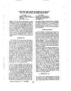
The FuzzBug is a small mobile robot (approximately 6 x 6 x 6 inches). Two independently-motorized side wheels are used to drive the robot in the desired direction by controlling the speed and direction of each motor. Passive wheels located in the front and in the back provide stability. The total weight is approximately 2 kg. For on-board processing power, two Mini Boards are used. The Mini Board 1 is small (2 x 3 inches) and has I/O ports as well as a 68HC811 microcontroller chip. The Mini Board resources include motor control ports, digital input ports, analog input ports, 256 bytes of RAM and 2048 bytes of EEPROM. One Mini Board is used to provide supervisory and motor control functions (the supervisor board). The second board is used for sensor input and processing (the FIU board). Inexpensive sensors are used to provide input data. Infrared (IR) emitter/detector pairs are used to detect the presence of obstacles. These IR sensors are analog devices which can detect the amount of modulated emitted light re ected by an object. Therefore, the value given by digitizing these analog signals can give proximity information. Another type of IR detector is used to track the IR LED beacon target. These sensors detect infrared light that is modulated at 40 KHz, which is the type of signal emitted by common infrared remote controls. The beacon detectors provide digital input data (i.e., 0 or 1{ the beacon is either visible or not visible to that particular sensor). The IR sensors are arranged symmetrically around the robot, in six sensor groups. Each sensor group contains an IR emitter/detector pair for obstacle proximity information and a beacon detector for target tracking information, both pointed in the same direction. The six groups cover all directions equally, as shown in Figure 1.
Dir: 10
Dir: 2
Dir: 3
Dir: 9
Dir: 8
Dir: 4
Dir: 7
Dir: 6
Dir: 5
= Sensor Group
Figure 1: Sensor groups and control directions beacon #1 FIU
direction #1 weight
proximity #1
Control Direction Combine Weights
beacon #6 FIU
direction #6 weight
proximity #6
Figure 2: Data ow of the FuzzBug controller
path in the direction of the sensor, and a high (H) reading an obstacle. The intermediate subsets represent III Two-Level Fuzzy Control Using Sen- indicates varying degrees of blockage. The beacon sensor is a digital signal. OFF indicates that the beacon was not detected; sor Groups ON indicates that the beacon was detected. The FuzzBug software is distributed across the two Nine fuzzy inference rules are used in the FIU, as Mini Boards; the Fuzzy Controller code is contained in the FIU board. Within the FIU software, modules must shown below: read all the IR sensors, fuzzify the inputs, and execute the FIU once for each of the six sensor groups. The output of 1. if (proximity is H) then (direction is VP) the FIU is a weight describing the suitability of that direction. When all six sensor groups have been processed, the 2. if (proximity is MH) and (beacon is O�) then (direcsix weights are combined using a circular defuzzi cation tion is VP) scheme to produce one nal control direction. Figure 2 3. if (proximity is MH) and (beacon is On) then (direcshows the data ow. Note that one copy of the FIU code tion is P) is used for each sensor group. The FIU uses two inputs, from the two sensors in each 4. if (proximity is M) and (beacon is O�) then (direcsensor group. Figure 3 shows the membership functions tion is P) of the input variables. The proximity sensor has ve fuzzy 5. if (proximityis M) and (beacon is On) then (direction subsets to its domain. A low (L) reading indicates a clear is F) 1 The Mini Board was designed by Fred Martin of MIT. Its de6. if (proximity is ML) and (beacon is O�) then (direcsign has been placed into the public domain via the comp.robotics Internet newsgroup. tion is F)
FuzzBug Beacon Tracking Without Obstacles M (Medium)
Truth Value L (Low)
ML (Medium Low)
400
MH (Medium High)
H (High)
350 Angle (degrees)
1
300 250 200 150 100 50 61
58
55
52
49
46
43
40
37
34
31
28
25
22
0 19
Proximity sensor membership functions
16
IR Signal
13
L5
7
L4
10
L3
4
L2
1
L1
Time (seconds)
Truth Value
Figure 4: Results of defuzzi cation with no obstacles. The dashed line indicates the direction in which the beacon was detected. The solid line indicates the resulting direction command.
On 1
Off
1 0 Beacon detector membership functions
Beacon Signal
Figure 3: Input membership functions of the FIU. L1 { L5 were determined experimentally. 7. if (proximity is ML) and (beacon is On) then (direction is G) 8. if (proximity is L) and (beacon is O�) then (direction is G) 9. if (proximity is L) and (beacon is On) then (direction is VG) In the second level of the controller, the direction weights are combined and discretized into one of twelve possible directions of motion. Figure 1 shows the commandable directions, as well as the sensor group directions which provide the input. In ideal conditions, one would expect the IR beacon to be detected by one or two (or possibly three) adjacent sensors only. This would make defuzzi cation of the direction weights relatively straightforward. However, in operational testing of the FuzzBug, it was found that the LED beacon may be detected by nonadjacent sensors, sometimes leaving `holes' where no beacon was detected. The circular defuzzi cation algorithm was designed to correct this problem. The algorithm handles the wraparound caused by the circular nature of the directions. A weighted average is then performed on this one area to yield the nal control direction. More details can be found in [4]. The e�ciency of the two-level fuzzy controller comes in part from limiting the number of input and output variables used by the FIU. Limiting the inputs and outputs e�ectively reduces the number of rules required, which reduces the complexity, execution time, and memory requirements. Reusing the FIU code also reduces memory consumption, which was critically limited in the FuzzBug. An alternative to reusing FIU code is to use multiple parallel processors. In this way, the concept of symmetric sensor groups results in inherent parallelism. The sensor group and corresponding FIU can be viewed as an intelligent sensor subsystem.
IV Performance Results and Evaluation The FuzzBug navigation system was tested under various conditions. The FuzzBug performed well at tracking both a stationary or moving beacon, without the presence of obstacles. Response was not quite as good from the side positions (i.e., 90 degrees and 270 degrees). This behavior can be explained by describing the conversion from commanded direction to motor control. The conversion method allows the FuzzBug to either go forward or backward, depending on which direction requires the lesser turn. When the beacon is directed at 90 degrees, the sensed direction sometimes \bounces" back and forth across the 90 degree line. This has the e�ect of making the FuzzBug oscillate back and forth as the direction changes. This behavior was corrected by forcing the FuzzBug to go straight instead. The rationale is that eventually, the beacon will be detected in another direction, causing the FuzzBug to turn correctly. The FuzzBug was also tested in a eld of obstacles, both with and without a beacon target. The performance was generally good, within the limitations of the IR proximity sensors. Because the IR sensors are light-sensitive, shadows tend to be sensed as obstacles. Also, di�erent obstacles re ect the IR beam di�erently, depending on the color and whether the surface is shiny or matte. In the tuning of the membership functions, we took a conservative approach, assuming that it was better to avoid all obstacles, including imagined ones. To collect quantitative results of the FuzzBug's navigation system, data was collected with a stationary FuzzBug. The beacon target was moved around the FuzzBug in a 360 degree circle. Beacon-tracking was measured both without any obstacles and with one obstacle at a known position. Figures 4 and 5 show the results. With no obstacles, the FuzzBug was able to track the beacon quite well. The four \blips" represent those times when the FuzzBug did not sense the beacon at all. In all other cases, the commanded direction was the same as the sensed direction of the beacon. This test may appear somewhat trivial; however, with noisy and inconsistent sensors, the beacon is often detected by more than one sensor and not necessarily adjacent sensors. As a result, the pattern of the nal weights can sometimes be confusing. As shown in the graph, the defuzzi cation algorithm used to combine the weights worked quite well.
FuzzBug Beacon Tracking: Obstacle at 120 degrees 400
Angle (degrees)
350 300 250 200 150 100 50 47
45
43
41
39
37
35
33
31
29
27
25
23
21
19
17
15
13
9
11
7
5
3
1
0 Time (seconds)
Figure 5: Results of defuzzi cation with one obstacle at 120 degrees. The dashed line indicates the direction in which the beacon was detected. The solid line indicates the resulting direction command. In the second test, shown in Figure 5, one obstacle was placed at 120 degrees. In this case, when no beacon is detected, the commanded direction would be 300 degrees (i.e., 180 degrees away from the obstacle). When a beacon is detected, the commanded direction should be essentially the same as the beacon's direction until the beacon gets too close to the obstacle. Then, the commanded direction should turn the FuzzBug away from the obstacle, but still in the same general direction as the beacon. The second graph re ects these results. Initially, the beacon is not active, and the commanded direction is 300 degrees. Later, when the beacon is hidden by the obstacle, the commanded direction is again 300 degrees. As the beacon approaches the direction of the obstacle, the commanded direction turns the FuzzBug slightly away from the obstacle. When the beacon is detected right at 120 degrees (at 9 and 20 seconds), the obstacle's presence cancels the beacon direction, and the commanded direction is set to 300 degrees. This behavior represents a tradeo� in design goals. The rules and membership functions could be designed to turn the FuzzBug slightly away from the obstacle. However, in real-world operation, a backup function is actually more useful. Fuzzy logic proved to be a good control method for use with the noisy proximity sensors. Using a discrete method, the IR sensors would either show the complete presence of an obstacle or no obstacle at all. The boundary would be a single threshold value. Unfortunately, with light-sensitive sensors, this threshold would change depending on the ambient level of light. This condition exists in the fuzzy implementation as well, but using fuzzy logic allows the boundary to be gradual instead of a sharp line. This has the e�ect of smoothing out the e�ects of the variations. If a discrete method were used, the performance would be even more sensitive to the lighting conditions.
V Conclusions
The fuzzy control strategy used in the FuzzBug is not intended to supersede the fuzzy behaviorist approaches described in [6, 7] but rather to be used in conjunction with them. That is, sensors and behaviors that have a natural coupling could be combined to form a higher level (more intelligent) behavior. These higher-level be-
haviors could then be used within the fuzzy behaviorist architectures. The advantage of the FuzzBug fuzzy control strategy is that it reduces complexity and minimizes the required resources while at the same time providing for an easy coupling between control actions. Also, the use of symmetric groups promotes scaleability and parallel processing. The two-level fuzzy control approach used in the FuzzBug could be extended to other applications, especially those requiring information from multiple sensors and di�erent types of sensors. The scheme could certainly be extended for use in other two-dimensional or three-dimensional target-tracking applications.
Acknowledgement
We would like to thank Dr. Richard Volz, Dr. John Yen, and Dr. Reza Langari for their support. We also thank Charath Ram and Soon-Lin Yeap for their assistance.
References
[1] Ronald C. Arkin. Motor schema based navigation for a mobile robot: An approach to programming by behavior. In Proceedings of the 1987 IEEE International Conference on Robotics and Automation, pages 264{ 271, 1987. [2] R. A. Brooks. A layered intelligent control system for a mobile robot. In Robitics Research: Third International Symposium, pages 365{372, 1985. [3] R. A. Brooks and J. H. Connell. Asynchronous distributed control system for mobile robot control. In Proceedings of SPIE, volume 727, pages 77{84, 1986. [4] Sean Graves, Marjorie Skubic, and John Mollenhauer. The FuzzBug mobile robot. Technical Report 93-040, Department of Computer Science, Texas A&M University, May 1993. [5] David W. Payton, J.K. Rosenblatt, and D.M. Keirsey. Plan guided reaction. IEEE Transactions on Systems, Man, and Cybernetics, 20(6):1370{1382, 1990. [6] Fran�cois G. Pin and Hiroyuki Watanabe. Driving a car using re exive fuzzy behaviors. In Proceedings of the 1993 IEEE International Conference on Fuzzy Systems, pages 1425{1430, 1993. [7] Alessandro Sa�otti, Enrique H. Ruspini, and Kurt Konolige. Blending reactivity and goal-directedness in a fuzzy controller. In Proceedings of the 1993 IEEE International Conference on Fuzzy Systems, pages 134{ 139, 1993. [8] John Yen and Nathan P uger. Path planning and execution using fuzzy logic. In Proceedings of the AIAA Conference on Guidance, Navigation, and Control, volume 3, pages 1691 { 1698, New Orleans, LA, August 1991.