A 6 VPP, 52 dB, 30-dB dynamic range, 43 Gb/s InP DHBT differential limiting amplifier J.-Y. Dupuy, A. Konczykowska, F. Jorge, M. Riet, P. Berdaguer, J. Godin III-V Lab, a joint lab of 'Alcatel-Lucent Bell Labs France', 'Thales Research and Technology' and 'CEA Leti' Route de Nozay, 91460 Marcoussis, FRANCE
[email protected] Abstract — We report the design, fabrication and measurement of a 43 Gb/s differential limiting amplifier integrating a transimpedance amplifier (TIA) as input stage and a distributed amplifier (Driver) as output stage, realised in a 1.5-µm indium phosphide (InP) double heterojunction bipolar transistor (DHBT) technology. With a differential gain higher than 52 dB, the TIA-Driver provides a constant 6 VPP differential output amplitude for an input amplitude ranging from 12.7 mVPP to 405 mVPP, achieving more than 30 dB of electrical dynamic range, for a power consumption of 2.7 W. Designed to be used between a photodiode and an electro-optical modulator, this circuit is well suited for optical-to-electrical-to-optical (O-E-O) wavelength converters at up to 43 Gb/s. Index Terms — Indium phosphide, double heterojunction bipolar transistor, distributed amplifiers, optical fiber communications.
I.
INTRODUCTION
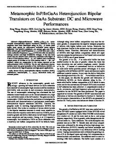
To face the growth of the internet traffic, typically doubling every eighteen months, the capacity of the global network needs to be continuously increased. Besides optical transport, node functions (like routers) must also be scaled [1]. In that respect, wavelength converter is a key component [2], about which many years of research have been carried out, mostly focusing on all-optical approaches. However practical implementation has usually been based on the optoelectronic approach. Still today, as ever more functionalities are required in order to make the network management more efficient, a so-called hybrid optoelectronic solution is proposed [3, 4, 5], in which optical and electrical technologies are optimally combined. To scale routers’ interface rate beyond 10 Gb/s, 40Gb/s wavelength converters based on the O-E-O approach are thus a key enabler. As depicted in Fig. 1, this kind of wavelength converter is composed of a photodiode, a transimpedance amplifier, a modulator driver, an electro-optical modulator and a laser [2]. The electronic circuit part is required to have a limiting characteristic so as to provide a constant driving signal to the modulator over a wide input dynamic range. Although many 40G trans-impedance amplifiers and modulator drivers have already been realised, during development of 40G optical transceivers for OOK, DPSK and DQPSK modulation formats, single-chip solutions have usually not been developed.
λout λin
λout E/O O/E
TIA
Driver
Figure 1: O-E-O wavelength converter principle
Yet, as the bit rate is increased beyond 10 Gb/s, signal integrity issues can become serious and integration can bring valuable improvement, in addition to cost reduction. However, the gain required from the photodiode to the modulator is very high (40 to 60 dB of insertion gain, corresponding to 74 to 94 dBΩ trans-impedance gain), and can cause serious oscillation issues [6]. In [7], a 60 dB limiting amplifier with 55-dB dynamic range is realized in SiGe HBT technology. It operates at 10 Gb/s and provides up to 2 VPP output differential swing. In [8], a 41 dB limiting amplifier with 25 mVPP sensitivity at 50 Gb/s is realized in 0.35-µm SiGe HBT technology, providing up to 1.8 VPP differential output swing. In [9], a 40 dB (6 kΩ transimpedance gain), 43 Gb/s differential trans-impedance limiting amplifier with auto-zero feedback, 35.6-dB dynamic range and providing 0.8 VPP differential output swing is realised in 1-µm InP SHBT technology. Finally, in [10], a 65nm CMOS 60 dB limiting amplifier integrating a TIA with retiming function and distributed output stage with digitally controllable pre-emphasis function is demonstrated. It operates nominally at 39 Gb/s and up to 60 Gb/s with some quality degradation. It provides up to 2.4 VPP differential output swing. Although results reported in [7-10] are state-of-the-art, none provide high enough output voltage swing with maintained signal quality for use in optoelectrical wavelength converters as modulators usually require more than 2-2.5 VPP of driving amplitude. In this paper, we present an InP DHBT circuit integrating a TIA as input stage and distributed amplifier as output stage. It is fully differential, operates either in single-ended or differential configuration, with either DC or AC coupling and includes input threshold controls and output peak detectors.
978-1-61284-712-2 /11/$26.00 ©2011 IEEE
x6
Transimpedance amplifier
Limiting amplifiers
Coplanar 50-Ω interface
Limiting amplifier
Split differential stage Distributed amplifier
Figure 2: TIA-Driver block diagram
This single-chip solution provides all the performances and controls required for use in optoelectronic wavelength converter applications at 43 Gb/s: large input dynamic range (12.7 mVPP sensitivity and overload higher than 405 mVPP corresponding to more than 30-dB dynamic), large output swing capability on 50 Ω load (tunable up to 6 VPP differential amplitude), high signal quality (signal-to-noise ratio higher than 11 and added rms jitter lower than 450 fs). It consumes 2.7 W when biased for 6 VPP differential output swing. The circuit was fabricated using III-V Lab’s 1.5-µm InP DHBT process [11]. II.
CIRCUIT DESIGN
As depicted in Fig. 2, the TIA-Driver circuit is based on a fully differential architecture. The TIA part ensures sensitivity, gain and limiting behaviour. The Driver provides additional gain and large swing driving capability. A 50 Ω interface with 500-µm long coplanar lines is used between the TIA and the Driver. While the length of 500 µm is linked to process constraints on chip size and minimisation of input and output lines, it furthermore allows to better isolate the TIA and Driver parts, as overall gain is high and oscillations may occur. A. TIA The input stage is a differential trans-impedance amplifier based on a differential pair amplifier and level-shifting emitter follower, the output signal of which is fed back with two resistors in a shunt-shunt topology. Two high value resistors are connected to both inputs for external threshold adjustment. Following are three limiting amplifiers, for gain, common mode rejection, isolation and dynamic range. They are composed of one Cherry-Hooper amplifier and two differential pair amplifiers, with inter-stage emitter followers for level-shifting and active impedance transformation. Output DC monitoring has been included by connecting both outputs of the third limiting amplifier to two on-chip RC low pass filters with few-MHz cut-off frequency. Lower cut-off frequency, typically a few kHz, requires external 10-to-100-nF capacitors, easily realisable with small form factor
components. The TIA and limiting amplifiers operate from a -3.3 V supply, consume around 130 mA (0.43 W) and provide a limiting output swing of 2x350 mVPP with 50 Ω impedances. B. Driver A modified active feedback Cherry-Hooper limiting amplifier with emitter followers and 50 Ω parallel resistors is used as buffer before the distributed amplifier for proper isolation. Two large resistors are connected to the input of the buffer for crossing point adjustment. Following is the distributed amplifier. Fully differential, it is composed of six cells distributed along coplanar lines. Based on the active loss compensation technique [12], each elementary cell is a differential cascode amplifier with double emitter follower at the input. The former is for isolation and optimisation of output impedance while the later is for optimisation of input impedance. Large emitter degeneration has been used to compensate for implementation parasitic, especially the emitter-to-emitter interconnect parasitic due to the split architecture (Fig. 2). Operating from four power supplies and one gain control, the driver can provide up to 6 VPP differential output swing, consuming 2.2 W. The circuit was fabricated using our InP DHBT 1.5-µm process, exhibiting 225/240-GHz FT/FMAX and 7.5 V breakdown voltage (BVCEO) [11]. A microphotograph of the 1.5 x 3.6-mm² chip is presented in Fig. 3.
Figure 3: TIA-Driver microphotograph (chip size = 1.5 x 3.6 mm²)
III.
EYE DIAGRAM MEASUREMENTS
The circuit was measured on wafer at 43 Gb/s with an Agilent 86100C DCA sampling oscilloscope. 10.75-Gb/s signals from a bit pattern generator were multiplexed to 43 Gb/s and cleaned by a DFF. The resulting signal is presented in Fig. 4: eye amplitude, quality factor (S/N), rms jitter and rise/fall time are respectively 97.2 mVPP, 17.24, 307 fs and 7.1/6.0 ps.
Figure 4: 43-Gb/s input eye diagram (25 mV & 10 ps / div.)
B. Dynamic range Using the same measurement set-up, simply varying the output amplitude of the DFF with a dedicated control pin and using additional 10-dB, 20-dB and 30-dB external attenuators, the input signal amplitude was decreased from 405 mVPP to 4.5 mVPP (39-dB dynamic range). The signal quality is fairly constant from 405 mVPP to 79.7 mVPP (S/N > 17 and rms jitter ≤ 311 fs), while from 79.7 mVPP to 14.1 mVPP, S/N progressively decreases to 5.6 and rms jitter progressively increases to 900 fs (input signals below 14.1 mVPP were not directly measured, their amplitude was derived knowing DFF’s output amplitude and the attenuation used). Depicted in Fig. 6 is TIA-Driver’s output differential amplitude variation in function of the input amplitude. Less than 1 % amplitude variation from 405 mVPP to 12.7 mVPP (30-dB dynamic range) has been measured with no significant quality degradation, except some jitter degradation at 12.7 mVPP, which may be due to the input signal jitter increase as mentioned before.
A. Output eye diagrams TIA-Driver’s single-ended output eye diagrams are presented in Fig. 5, with signal applied on first input (Fig. 5 (a) and (b), and signal applied on second input (Fig. 5 (c) and (d)): eye amplitude, quality factor (S/N), rms jitter and rise/fall time are respectively: (a) 3.15 VPP, 13.8, 580 fs and 8.2/6.0 ps (b) 2.97 VPP, 10.9, 554 fs and 8.9/6.2 ps (c) 3.15 VPP, 13.7, 674 fs and 8.2/6.0 ps (d) 2.95 VPP, 10.7, 522 fs and 8.9/6.2 ps Although little difference between two outputs is noticeable, quality factor remains higher than 10.5, rms jitter lower than 700 fs, rise and fall time lower than 9 ps and amplitude around 3 VPP.
Figure 6: Output amplitude versus input amplitude measured at 43 Gb/s
(a) (b) Signal on input 1, output 1 measured Signal on input 1, output 2 measured
(c) (d) Signal on input 2, output 1 measured Signal on input 2, output 2 measured Figure 5: 43-Gb/s output eye diagrams (700 mV & 10 ps / div.)
Linear gain of limiting amplifiers is not easy to assess. As it is very high, the circuit is operating in gain compression regime very early. S-parameters measurements could not allow determining it as stability problems occur when the TIADriver is biased for nominal gain and driven with a smallsignal input signal. As depicted in Fig. 6, a linear fit between the curve’s first two points gives a differential gain of 52 dB, which represents a lower bound of the linear gain, as compression is already present. A performance summary and comparison with state of the art is provided in Table 1.
TABLE I.
PERFORMANCE SUMMARY AND STATE OF THE ART
Parameter
Unit
[7]
[8]
[9]
[10]
This work
Maximum bit rate
Gb/s
10
56
43
39 - 60
43
Sensitivity
mVpp < 3.5 (1) µApp
Overload
Vpp mApp
2 -
-
6
-
> 0,4 -
Dynamic range
dB
55
-
35.6
-
> 30
Max. output swing (differential)
Vpp
60
41
40
60
≥ 52
Power consumption (for max. output swing)
W
1.1
0.42
0.45
0.73
2.7
Chip area
mm²
1.2 x 2.6
0.6 x 0.6
Process node Material Transistor FT FMAX
GHz GHz
0.35 µm 1 µm SiGe SiGe InP HBT HBT HBT 47 200 160 65 160
25 (2) -
8 (3) 5 / 40 (4) 12,7 (5) 100 (3)
1 x 1.8 1 x 1.8
1.5 x 3.6
65 nm 1.5 µm Si InP CMOS DHBT 225 240
and V. Nodjiadjim from III-V Lab for modelling, J. Simsarian and A. Adamiecki from Alcatel-Lucent Bell Labs for fruitful discussions. REFERENCES [1]
[2]
[3]
[4]
[5]
[6]
[7] (1) At BER = 10-9 (2) At BER = 10-6 and at 50 Gb/s (3) At BER = 10-12 (4) Eye height / eye amplitude; no BER measurement (5) Eye amplitude; no BER measurement
IV.
CONCLUSION
A differential limiting amplifier for 43-Gb/s operation has been realised using III-V Lab’s 1.5-µm InP DHBT technology. Integrating a TIA and a distributed amplifier, a gain higher than 52 dB is achieved. It provides a constant 6 VPP differential output voltage swing over a 30-dB electrical dynamic range, for a power consumption of 2.7 W. This TIADriver is thus well suited for 43 Gb/s O-E-O wavelength converters. Threshold controls allow the circuit to work in either single-ended or differential configuration, so that it can be used for OOK, DPSK or DQPSK modulation formats. DC coupling capability allows utilisation in burst mode operation for packet router applications, as demonstrated in [13], in which the TIA-Driver was successfully implemented in a 40-Gb/s burst mode wavelength converter. ACKNOWLEDGMENT The authors are grateful J. Moulu from III-V Lab for CAD support, T.K. Johansen from Technical University of Denmark
[8]
[9]
[10]
[11]
[12]
[13]
J. Gripp, J. E. Simsarian, J. D. LeGrange, P. Bernasconi, D. T. Neilson, "Photonic terabit routers: The IRIS project," in Proc. OFC’10, Paper OThP3, pp.1-3, 21-25 March 2010 K. E. Stukjaer, C. Joergensen, S. L. Danielsen, B. Mikkelsen, M. Vaa, R. J. Pedersen, H. Povlsen, M. Schilling, K. Daub, K. Dutting, W. Idler, M. Klenk, E. Lach, G. Laube, K. Wunstel, P. Doussiere, A. Jourdan, F. Pommerau, G. Soulage, L. Goldstein, J.Y. Emery, N. Vodjdani, F. Ratovelomanana, A. Enard, G. Glastre, D. Rondi, R. Blondeau, "Wavelength conversion devices and techniques," in Proc. ECOC '96, pp. 33- 40 vol.4, 15-19 Sept. 1996 H. Takenouchi, R. Urata, T. Nakahara, T. Segawa, H. Ishikawa, R. Takahashi, "First demonstration of a prototype hybrid optoelectronic router," in Proc. ECOC '09, pp.1-2, 20-24 Sept. 2009 D. Chiaroni, R. Urata, J. Gripp, J. E. Simsarian, G. Austin, S. Etienne, T. Segawa, Y. Pointurier, C. Simonneau, Y. Suzaki, T. Nakahara, M. Thottan, A. Adamiecki, D. Neilson, J.C. Antona, S. Bigo, R. Takahashi, V. Radoaca, "Demonstration of the interconnection of two optical packet rings with a hybrid optoelectronic packet router," in Proc. ECOC '10, pp.1-3, 19-23 Sept. 2010 Y. Suzaki, R. Urata, T. Nakahara, H. Takenouchi, R. Takahashi, "Hybrid optoelectronic router for optical packet switching," in Proc. OECC '10, pp.538-539, 5-9 July 2010 W. Seiner, H.-M. Rein, J. Berntgen, "Substrate coupling in a high-gain 30-Gb/s SiGe amplifier-modeling, suppression, and measurement," Journal of Solid-State Circuits, vol.40, no.10, pp. 2035- 2045, Oct. 2005 Yu. M. Greshishchev, P. Schvan, "A 60-dB gain, 55-dB dynamic range, 10-Gb/s broad-band SiGe HBT limiting amplifier," Journal of SolidState Circuits, vol.34, no.12, pp.1914-1920, Dec 1999 M. Groሷzing, M. Schmidt, M. Berroth, "A 56 Gbit/s 0.35 µm SiGe Limiting Amplifier with 2.4 THz Gain-Bandwidth-Product," in Proc. CSICS '10, pp.1-4, 3-6 Oct. 2010 H. Tran, F. Pera, D. S. McPherson, D. Viorel, S. P. Voinigescu, "6-kΩ 43-Gb/s differential transimpedance-limiting amplifier with auto-zero feedback and high dynamic range," Journal of Solid-State Circuits, vol.39, no.10, pp. 1680- 1689, Oct. 2004 R. A. Aroca, P. Schvan, S. P. Voinigescu, "A 2.4 Vpp, 60-Gb/s, mmWave DAC-Based CMOS Driver with Adjustable Amplitude and Peaking Frequency," in Proc. CSICS '10, pp.1-4, 3-6 Oct. 2010 J. Godin, A. Konczykowska, M. Riet, J. Moulu, Ph. Berdaguer, F. Jorge, “InP DHBT Integrated Circuits for Fiber-Optic High-Speed Applications”, IEICE TRANSACTIONS on Electronics, vol. E89-C, no.7, pp.883-890, July 1st 2006 K. W. Kobayashi, R. Esfandiari, A. K. Oki, "A novel HBT distributed amplifier design topology based on attenuation compensation techniques," Transactions on Microwave Theory and Techniques, vol.42, no.12, pp.2583-2589, Dec 1994 J. E. Simsarian, J. Gripp, J. D. LeGrange, A. L. Adamiecki, P. Bernasconi, L. L. Buhl, E. C. Burrows, J.-Y. Dupuy, C. D. Howland, F. Jorge, A. Konczykowska, D. T. Neilson; "A Load-Balanced Optical Packet Router Interconnected With a 10-GbEthernet Electronic Router," Photonics Technology Letters, vol.23, no.16, pp.1124-1126, Aug.15, 2011