logic verification using simulation is often too slow. As an alternative, hardware
emulation can accelerate this process by several orders of magnitude. FPGA ...
IEEE 2007 Custom Intergrated Circuits Conference (CICC)
ASIC Design and Verification in an FPGA Environment Dejan Markovic*, Chen Chang, Brian Richards, Hayden So, Borivoje Nikolic, Robert W. Brodersen Berkeley Wireless Research Center, University of California, Berkeley, USA * Now with the Department of Electrical Engineering, University of California, Los Angeles, USA Abstract -- A unified algorithm-architecture-circuit co-design environment for dedicated signal processing hardware is presented. The approach is based on a single design description in the graphical Matlab/Simulink environment that is used for FPGA emulation, ASIC design, verification and chip testing. This unified description enables system designer with a visibility through several layers of design hierarchy down to circuit level to select the optimal architecture. The tool flow propagates up circuit-level performance and power estimates to rapidly evaluate architecture-level tradeoffs. The common Simulink design description minimizes errors in translation of the design between different descriptions, and eases the verification burden. The FPGA used for emulation can be used as a low-cost tool for testing of the fabricated ASIC. The approach is demonstrated on an ASIC for 4×4 MIMO signal processing.
I. INTRODUCTION Traditional approaches to implementing signal processing algorithms in an ASIC involve creating a design and translating between multiple design descriptions: an abstract algorithm is analyzed and optimized in Matlab or C; then it is mapped onto an architecture using behavioral or structural description; in the process, a fixed-point description replaces a floating point version of the design; it is partitioned into various design fabrics and mapped into an ASIC/SoC; the design is checked for equivalence between different descriptions; and the test vectors are once again translated for use in a logic analysis system for final hardware testing. Each translation step, whether manual or automated, requires additional verification to confirm that the original design has been preserved. More importantly, changes in the design description impede the system and architecture designers’ visibility into the basic implementation tradeoffs at microarchitecture and circuit level. We proposed in [1] to use Simulink as the design editor, because it is common to system designers and its discrete-time computation model can be made bit-true and cycle-accurate with respect to the hardware. This approach provides a common description of the algorithm and ASIC. It merges design, optimization, and ASIC hardware verification steps within the widely adopted Matlab/Simulink design environment. In chip design, logic errors need to be eliminated early in the design to avoid costly hardware re-spins. Unfortunately, logic verification using simulation is often too slow. As an alternative, hardware emulation can accelerate this process by several orders of magnitude. FPGA chips present a viable technology for emulating complex algorithms, leveraging advances in performance, capacity, and software support for FPGAs. As an example, emulation of the entire physical layer processing for the 802.11a standard is feasible in an FPGA, [2]. This presents an opportunity to leverage the FPGA technology for real-time at-speed ASIC verification, as
1-4244-1623-X/07/$25.00 ©2007 IEEE
Matlab™
Simulink Word-length Architecture
behavioral Speed Power Area
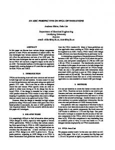
Behavioral HDL FPGA board ASIC board Real-time hardware verification Fig. 1.
In-house tool
HDL Generation Logic Synthesis HDL Simulation
logical Speed Power Area
Mapped HDL
Backend tool Loop Retiming Place & Route
physical
Simulink-based ASIC design and verification environment.
described in [3]. In this paper, we demonstrate how the unified description can be used to perform high-level tradeoffs between area and power for a fixed-throughput DSP algorithm. We also demonstrate the use of the same description and emulation hardware to test a fabricated chip. II. UNIFIED ASIC/FPGA DESCRIPTION IN SIMULINK The FPGA hardware description cannot be used as is for ASIC designs due to incompatibilities between many of the low-level primitive components. To leverage an existing Simulink design entry that is used for FPGA programming, an in-house tool [3, 4] was developed. The tool synthesizes basic primitives based on the behavioral RTL, and performs initial top-level synthesis for an ASIC based on the dataflow graph connectivity in Simulink, Fig. 1. The tool also performs HDL simulation to confirm functional equivalency between the two hardware descriptions. The mapped ASIC netlist is optimized using a set of custom scripts for register retiming and logic optimization, before entering the final stage of physical layout synthesis through a commercial backend flow. This approach allows relatively straightforward mapping of a parallel architecture from the dataflow graph onto silicon. Architectural feedback about speed, power, and area of hardware macros is mapped back to the Simulink model, enabling exploration of architectures for improved ASIC power and area. III. ARCHITECTURE EXPLORATION IN SIMULINK The architecture exploration starts from the direct-mapped parallel architecture (one-to-one correspondence between algorithmic operations such as add, multiply etc. and hardware blocks). This architecture is well defined, and serves well as an initial design point. The initial architecture, however rarely meets timing requirements in the most energy/area-efficient way.
21-7-1
737
compilation to utilize sizing, as shown in Fig. 2. Timing constraints are shifted to the reference supply to balance sensitivities at a reduced supply voltage. The Simulink environment is used to implement several other design procedures. A wordlength reduction routine based on perturbation theory is performed in Simulink [6] to reduce the hardware area. The Simulink block-based design methodology also allows integration of 3rd party IP blocks such as SRAM modules provided by an ASIC foundry. The final design optimized in Simulink is mapped to two hardware targets: the FPGA hardware, and the gds2 physical layout.
Energy Initial design
Initial design
wordlength Initial synthesis gate sizing
parallel
Optimal design
time-mux
VDD scaling
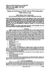
Area Fig. 2.
Delay
0
Energy-delay space for pipeline logic is the tool for comparing architecture and technology options. Total design area is shown.
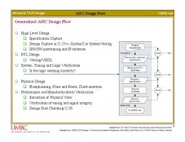
For a given communications algorithm that works with a fixed bandwidth, the architecture is strongly influenced by the scaling of the underlying technology. Figure 2 illustrates the methodology for choosing the best architecture for a given technology based on energy-delay characterization of datapath logic to jointly minimize power and area. The design process starts from the initial design sized for minimum delay at its nominal supply and threshold. Optimal design is achieved by balancing sensitivity of the underlying pipeline logic stages in the entire design, [5]. This framework can be used to optimize architecture for a given technology. For example, intrinsic computational efficiency of silicon due to scaling is roughly equivalent to adding one level of parallelism in terms of performance. Architecture and technology options therefore have to be jointly considered early in the design process. Basic architectural building blocks, such as adders and multipliers are characterized in the latency vs. cycle time space, Fig. 3. The impact of voltage scaling is estimated from the transistor level simulation of the FO4 gate delay. Block characterization data allows decoupling of register retiming and voltage scaling issues by choosing the correct amount of block-level pipelining for a given clock cycle TClk constraint. The remaining issue of balancing the tradeoffs with respect to gate sizing and voltage scaling is also performed sequentially in synthesis environment. Prior work [5] demonstrated that gate sizing is the most effective at small incremental delays relative to the minimum delay, so the design is initially synthesized with a 20% slack followed by an incremental Library blocks / macros synthesized @ VDDref
Cycle Time
IV. FPGA-ASSISTED ASIC VERIFICATION The final step in the chip making process is the testing of the fabricated ASIC. The Simulink design environment is also used to facilitate FPGA-assisted chip testing, thus closing the loop of design, optimization, and test. The existing commercial FPGA-based ASIC verification solutions [7] require users to construct custom hardware testbench for FPGA typically using low-level HDL. This process is time consuming and error prone, and requires FPGA expertise to leverage all of the debugging features available on an FPGA. Unlike the traditional approach, the Simulink description of an ASIC architecture also implicitly provides the testbench. Xilinx System Generator (XSG) tools can leverage the existing testbench to put the FPGA in the loop of the software simulation for cycle-accurate verification. However, such hardware-in-the-loop verification speed is limited by the available PC-to-FPGA communication interfaces, such as JTAG or Ethernet. In both cases, the maximum co-simulation speed is limited to a few MHz clock rate—far from the desired ASIC clock rate for interface to the analog radio subsystem. The FPGA portion of the flow, internally developed BEE Platform Studio (BPS) [8], leverages the embedded PowerPC cores available on high-end Xilinx FPGAs for in-circuit verification of the algorithm and the final ASIC. To ease the testbench creation burden on the ASIC designer, the BPS flow completely automates the FPGA backend generation, and
Pipeline logic scaling FO4 inv simulation
VDD scaling Speed Power Area TClk @ VDDref
TClk @ VDDopt VDDref
add
Latency Fig. 3.
gate sizing
mult
0
Block- and gate-level technology characterization.
Energy Fig. 4.
21-7-2
Custom Xilinx Platform Studio and hardware interface blockset.
738
-c-c-
ADDR D_IN WE
in
D_OUT
BRAM_IN
logic soft reg soft reg
-c-
soft reg
Simulink hardware model
out
ASIC board
out
ADDR D_IN WE
Client PC
D_OUT
BRAM_FPGA
in rst clk
-c-
soft reg
ADDR D_IN WE
Fig. 6. D_OUT
BRAM_ASIC sim_rst
reset reg0
logic
XSG core config
Fig. 5.
Simulink hardware interface model. The model is programmed onto FPGA for real-time hardware co-simulation.
augments the existing XSG Simulink library with FPGA system level component library, as shown in Fig. 4, to abstract away FPGA specific interface and debugging details. The FPGA system library has the following blocks: 1) software/hardware interfaces (registers, FIFOs, shared block RAM), for communication between the embedded processor core and the design under test; 2) external digital interfaces (GPIO ports), used for connection to an external ASIC chip under test; 3) external A/D and D/A interfaces for connection to analog radio subsystems; and 4) in-circuit debugging (vector signal generator, hardware scope), which are software controlled onchip debugging resources for verification of either the algorithm or the final chip at the target clock rate. Users can insert the FPGA system-level blocks to specific ASIC interfaces as well as internal nodes for debugging, as shown in Fig. 5. The FPGA logic and software device drivers are automatically generated by the BPS, and integrated in the Xilinx Embedded Development Kit backend flow. By default, the BPS design flow provides a simple user command shell, TinySH, that is used as an interactive interface to the embedded processor core via an on-board RS232 serial connection, shown in Fig. 6. This connection can be accessed directly through a terminal emulator running on the client PC, or through Matlab. Two Matlab routines are available, read_xps and write_xps [8], allowing programs to read or write memory and register contents on the FPGA board, via the serial port and TinySH. The debugging FPGA embedded processor core and the ASIC under test can run on independent clocks or the ASIC clock can be provided by the FPGA. All software/hardware interface blocks use asynchronous clock boundary crossing, and the processor can setup the debugging blocks for precise capture of the internal node data in real-time. Software input vectors can be generated either by the embedded processor and custom software code, or more conveniently directly loaded via the serial connection from the Matlab/Simulink environment. Similarly, the captured output data can be sent to Matlab environment for further analysis. In case of ASIC testing, the same input vectors can be sent both to the ASIC chip and the FPGA logic emulation of the ASIC, as shown in Fig. 1, then compared on the FPGA for output equivalency on a per clock cycle basis, hence closing the loop of algorithm to final ASIC chip verification.
RS232 ~Kb/s
FPGA board
serial GPIO ~130Mb/s
Existing hardware co-simulation model. interface model (Fig. 5) controls the ASIC.
ASIC board Simulink hardware
The performance of the hardware co-simulation interface shown in Fig. 6 is limited by the data rate of both the serial link between the client PC and the FPGA board, and the connections between the FPGA and ASIC boards. The realtime performance of the ASIC/FPGA co-simulation is limited by the serial GPIO bandwidth to about 130MHz. This speed is sufficient for dedicated signal processing hardware for communications, but can become a bottleneck. In addition, the process of controlling and transferring test vectors to and from the FPGA test board from the Matlab/Simulink environment in real-time is limited by the RS232 serial port bandwidth (~kb/s range). Block RAM memories are currently used as data buffers to provide real-time emulation capability. This approach works well for periodic inputs or internally generated testbench on the FPGA. The output data is currently being transferred into Matlab from the block RAM memories on the FPGA. Internal control circuits that flag discrepancies between the two hardware modules can be easily deployed for real-time comparison. V. FULLY FPGA-BASED TEST SETUP To overcome the I/O bandwidth limitation, we are currently implementing a fully FPGA-based test infrastructure as shown in Fig. 7. The client PC functionality from Fig. 6 is implemented on an Ethernet-enabled FPGA board managed by the BORPH operating system [9]. As a result, the original client PC reduces to a role of a simple terminal. All ASIC testing are controlled by the FPGA. This setup will then allow real-time ASIC debugging speed to be increased to about 500Mb/s of practical bandwidth over a Z-Dok differential connector. This bandwidth is compatible with the speed of the most advanced FPGA parts (e.g. Xilinx Virtex5). Having the testbench portion executing on a BORPH managed FPGA has two key advantages. First, the FPGA testbench can run at a higher clock rate. This setup eliminates the data I/O bottleneck and allows much higher ASIC test performance. Second, FPGA managed by BORPH has access to system resources such as the general UNIX file system that the host computer has access to. It allows the FPGA testbench to access the same test vector files as the top-level Simulink simulation for verification purpose. Figure 8 summarizes various phases of ASIC verification that include simulation, emulation, and test. The simulation can be simply carried in Simulink as pure software simulation. User Terminal
Fig. 7.
21-7-3
Ethernet
BORPH Z Dok FPGA board ~500Mb/s
ASIC board
Future hardware co-simulation model with BORPH operating system running on the FPGA.
739
ASIC
ASIC
I/O TB
I/O TB
Simulation
1 2
3 Emulation 4 Test
Fig. 8.
5 6
Simulink HDL
Simulink Simulink
Simulink Simulink
FPGA FPGA FPGA FPGA
HIL tools FPGA FPGA FPGA
Simulink FPGA Custom SW FPGA
Note: Pure SW Simulation Simulink-Modelsim Co-sim. Hardware-in-the loop Sim. Pure FPGA Emulation Testbench outside FPGA Testbench inside FPGA
Summary of FPGA-based ASIC verification.
Alternatively, we can simulate the behavioral HDL description of the ASIC design by Simulink-Modelsim co-simulation. A third form is the co-simulation of the final synthesized ASIC structural design with the Simulink testbench, which allows arbitrary non-Simulink subsystems to be verified. It also allows the hardware testbench to exercise a timing-accurate HDL simulation for a detailed ASIC verification. In the Emulation phase, Simulink can perform hardwarein-the-loop simulations where parts of the design are implemented in hardware and the rest in software; or do a complete FPGA emulation in real-time. Final ASIC test can be done by controlling test vectors from the outside client PC (Fig. 6) or embedding test vectors in FPGA hardware (Fig. 7). The proposed Matlab/Simulink environment supports design, optimization, and verification of dedicated DSP hardware. VI. ASIC EXAMPLE Using the approach presented, a multi-carrier MIMO chip that operates over many parallel frequency channels was designed, optimized, and verified [10]. Figure 9 is the result of functional at-speed (100MHz) verification of the ASIC driven by the FPGA, as in Fig. 5. The energy- and areaefficiency of the ASIC built using our methodology compares favorably to recently published baseband communications and media processors with high energy-efficiencies [11] and the high area-efficiencies [12]. Subsequently, few other ASICs, including multi-standard FIR and UWB processor were recently designed. With fully functional flow, the design cycle has been drastically reduced, to an order of several weeks from algorithm to final layout. VII. CONCLUSION Matlab/Simulink is a unified environment that closes the loop from algorithm development to final ASIC verification, thus improving the top-level decision making and increasing the design productivity. The methodology allows hardware emulation of the algorithm, optimized architecture description, and final ASIC verification, using the unified description. The same environment can be used for accelerated algorithm exploration. Other design optimization routines including wordlength reduction, architecture transformations, and hardware scheduling could be also facilitated from the unified
Fig. 9.
Eigen-mode tracking of a 4×4 MIMO channel. Hardware cosimulation result (solid: measured, dashed: theoretical).
Simulink description. The ASIC design made using the proposed approach is fully functional and achieves 2GOPS/mW of energy-efficiency and 20GOPS/mm2 of areaefficiency in a 90nm CMOS technology. ACKNOWLEDGMENTS The authors acknowledge funding support from C2S2 under MARCO contract 2003-CT-888 and BWRC member companies, STMicroelectronics and Xilinx for hardware support, P. Droz and H. Chen for FPGA infrastructure support. NSF CNS RI grant #0403427 provided the computing infrastructure. REFERENCES [1]
W.R. Davis et al., “A Design Environment for High-Throughput LowPower Dedicated Signal Processing Systems,” IEEE JSSC, pp. 420-431, March 2002. [2] C. Dick and F. Harris, “FPGA Implementation of an OFDM PHY,” in Proc. Asilomar Conf. 2003, pp. 905-909. [3] K. Kuusilinna et al., “Real Time System-on-a-Chip Emulation,” in Winning the SoC Revolution by H. Chang, G. Martin, Norwell, MA: Kluwer Academic Publishers, 2003. [4] [online] http://bwrc.eecs.berkeley.edu/Research/Insecta/default.htm [5] D. Marković, V. Stojanović, B. Nikolić, M. Horowitz, R.W. Brodersen, “Methods for True Energy-Performance Optimization,” IEEE JSSC, pp. 1282-1293, Aug. 2004. [6] C. Shi and R.W. Brodersen, "Automated Fixed-point Data-type Optimization Tool for Signal Processing and Communication Systems," in Proc. IEEE Design Automation Conf., June 2004, pp. 478-483. [7] [online] http://eve-team.com [8] Berkeley Emulation Engine 2, [online] http://bee2.eecs.berkeley.edu [9] H. So, A. Tkachenko, R.W. Brodersen, “A unified hardware/software runtime environment for FPGA-based reconfigurable computers using BORPH,” in Proc. Int. Conf. Hardware Software Codesign, Oct. 2006, pp. 259-264. [10] D. Markovic, R.W. Brodersen, and B. Nikolic, “A 70GOPS, 34mW Multi-Carrier MIMO Chip in 3.5mm2,” VLSI’06, pp. 196-197. [11] P. Mosch et al., “A 720µW 50MOPs 1V DSP for a Hearing Aid Chip Set,” in ISSCC Dig. Tech. Papers, Feb. 2000, pp. 238-239. [12] F. Arakawa et al., “An Embedded Processor Core for Consumer Appliances with 2.8GFLOPS and 36M Polygons/s FPU,” in ISSCC Dig. Tech. Papers, Feb. 2004, pp. 334-335.
21-7-4
740


![[Full] Physical Design Essentials: An ASIC Design ... - Google Sites](https://m.moam.info/img/260x300/full-physical-design-essentials-an-asic-design-goo_64783b01097c4744708c98f4.jpg)


