[3] M. Hirakawa, M. Tanaka, and T. Ichikawa. An Iconic Programming. System, HI-VISUAL. IEEE Transaction on Software Engineering,. 16(10):1178â1184, 1990.
CafePie – A Visual Programming Environment for CafeOBJ Tohru Ogawa and Jiro Tanaka Institute of Information Sciences and Electronics, University of Tsukuba, Tsukuba, Ibaraki 305-8573, Japan Abstract We have implemented a visual programming system CafePie. Program editing and execution in CafePie are performed in one window. All program editing operations are handled in a uniform manner. We propose to customize the object views, which prescribe the visible part of the program object. Data structures of the program can be visualized as users like by using visual transformation rules. These rules can also be edited using drag-and-drop operations. We call these visualized objects “realistic” expression. The users can edit and execute the program by using “realistic” expression. We have also implemented the prototype on CafePie.
1
Introduction
A visual programming system (VPS) [1] visualizes structures of programs in two or more dimensions using visual expressions such as graphics, pictures and so on. Various research works have been performed on VPS, such as Pict [2], HI-VISUAL [3] and PP [4]. In general, a visual style of programming is easier to understand for humans, especially for non-programmers or novice programmers. Moreover, the style can be useful in the software specification area, such as component based software [5, 6]. A tool qualifies as a visual programming if it is possible to build an application without textual programming. We have developed a system CafePie [7, 8, 9], which stands for Pictorial Interactive Environment for CafeOBJ. CafeOBJ is an algebraic specification language (ASL), a high-level declarative programming language. CafeOBJ 1
specification consists of module structures. Our system visualizes each module. We use the direct-manipulation techniques for program editing. Most of the editing operations are performed by using only a mouse. The same visualization schema is used for both program editing and execution. Since the program editing and execution are performed in one window, program modifications are reflected directly in program execution.
2
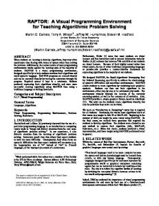
The “CafePie” System Assistant Operation Part Text Input Part Working Part
New-Field
Module Field
Figure 1: A Snapshot of CafePie Figure 1 shows a snapshot of CafePie. “Assistant Operation Part” consists of buttons in the upper part of the figure. This enables a user to load or save a file by the File button, set the CafeOBJ server by the Options button, and view textual guides by the Help button. “Text Input Part” is in the next part of the former. The user can input or modify the label of each editable icon by using this part. “Working Part” is the main part of the figure. The user edits a CafeOBJ program in this part. The “Module Field” in the “Working Part” shows the current CafeOBJ module to edit. The left side of the “Module Field” is the “New-Field,” which consists of essential icons such as sort, operator, variable, and equation. This field is used to make a new icon in the “Module Field.” We developed CafePie and implemented it in Java. CafePie was developed in Java Development Kit (JDKTM ). and this is usually implemented as a Java application. In Java application version, users can edit and execute programs 2
in the system. CafePie is also implemented as an applet on a Web browser. The applet version is used only for program editing. module SIMPLE-NAT { [ Zero NzNat < Nat ] signature { op 0 : -> Zero op s : Nat -> NzNat op _+_ : Nat Nat -> Nat { comm, assoc } } axioms { var N : Nat var M : Nat eq [0] : 0 + N = N . eq [1] : N + s(M) = s(N + M) . } } Figure 2: Program “simple-nat.mod” The following functions have been implemented in CafePie: • Input program objects by figures. Users can input each basic object of an ASL language using an icon. These icons can be edited by direct manipulation. • Generate visual icons from the codes automatically. Users can input a textual expression, and the system will generate icons from the expression. • Editing visual objects. Visual expressions can be edited at any time. Users can program visually using this function while they edit or revise programs that have already been generated from the textual programs of CafeOBJ. • Program save/load. Visually-edited programs can be saved to a file. Users load the file when necessary. CafePie saves the visual expressions after it converts them to CafeOBJ program expressions. • Program execution. A goal (term) represented by the visual icons can be executed. In this 3
case, CafePie is connected to the CafeOBJ interpreter. CafePie behaves like a visual interface in the program execution. For example, the file “simple-nat.mod”(Fig.2), which is a specification of natural numbers (under addition) written in CafeOBJ, is loaded by clicking on the File button. The program, visualized with pictorial objects, then appears in the Module Field of the Working Part (as in Fig.1). The visualized program can be edited by direct manipulation. If the edited program is saved, a CafeOBJ program file and another textual file that contains layout information are created.
2.1
Program Visualization in CafePie
“Visualization of program structure” means expressing the program structure using pictorial or graphical objects. We visualize the program structures of CafeOBJ by expressing the program elements with pictorial objects. Each pictorial object is called an “Icon.” We have chosen the following primitive elements for CafeOBJ: sort, operator, variable, and equation. The visualization rules for each icon are presented below. Each icon has a color and a shape as in the Table 1.
Table 1: Icons’ Colors and Shapes in CafePie Icon
Sort
Term
Operator
Variable
Equation
Module
Color Shape
Green Rect.
(Tree)
Light blue Oval
Orange Oval
White (label) (Balance)
Gray Field (Rect.)
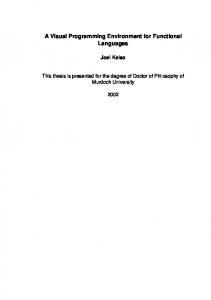
Sort: CafePie uses a directed graph to depict the sort orders. The sorts are represented in Fig.3 by green rectangular nodes as in the Table 1 (only shaded rectangles are seen in the manuscript) and the orders are represented by directed edges.
Figure 3: Sort Icon and Sort Relation 4
Figure 4: Term Icon
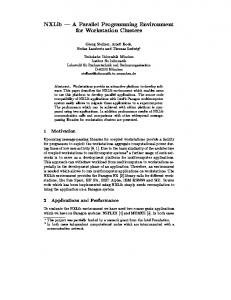
Term: A term is formed with operators and variables. The structure of a term is displayed as a tree. Fig.4 shows the tree structure of the term “OP1(OP0,V:Sort).” A component of a term, i.e. an operator or a variable, is represented by a node, and an arrow is drawn from the term to its superterm to express the super-sub relationship between these components. Operator and Variable: An operator is denoted by an operator symbol, its sort “coarity,” and its attributes “arities.” An operator is represented in Fig.5 by a light blue oval and has a label for the operator symbol as in the Table 1. The labels of the arities are arranged at the bottom part of the operator, and the label of the coarity is arranged at the top part of the operator. Arrows are drawn from arities to operator and from operator to coarity. A variable, which appears in Fig.6, is represented by an orange oval like the Table 1, and the sort of the variable is represented at its lower part.
Figure 5: Operator Icon Figure 6: Variable Icon Figure 7: Equation Icon Equation: CafePie is mainly concerned with the operational semantics of CafeOBJ, so equations are always regarded as rewrite rules. A label is arranged in the center top of the equation, as shown in Fig.7. The left side is arranged on the bottom left side of the label, and the right side is on the bottom right. Arrows from the left term to the label and from the label to the right term are drawn to form a balanced shape to represent a term rewriting rule as in the Table 1). Module Field: A CafeOBJ program consists of modules. A module is represented as a gray rectangle called a “field” as in the Table 1. The module contains other primitive elements: sort, operator, variable, and equation. We can edit these primitive elements.
2.2
Drag-and-Drop-based Program Editing
We use direct manipulation to implement program editing. Direct manipulation is easy to learn, and the user can immediately recognize any mistakes. Complex and obscure operations can cause unexpected consequences; simple operations enable a smoother program editing. All icon-editing operations are handled in a uniform manner, using a drag-and-drop operation [10]. This drag-and-drop technique is well known for its simplicity. For icon movement, the user moves the icon using the 5
drag-and-drop technique. If an icon already exists where the user wants to drop the icon, the two icons will overlap. Overlapping two icons with the drag-and-drop technique is important in the editing process. The process of the drag-and-drop method consists of: 1. Selecting an icon, 2. Moving (or dragging) the selected icon to another icon, and 3. Overlapping (or dropping) the selected icon with another icon. The target icon moves with the mouse cursor and remains visible throughout the movement. The user moves the icon by dragging it, without losing sight of what he is doing. We reexamined this technique to realize program editing. Program editing operations in CafePie involve making/deleting a relation between two sorts, adding/changing an arity of an operator, and creating/adding a subterm on a variable. Table 2 shows these program editing operations. An event is invoked when an icon (source) is overlapped onto another icon (target). After the event is invoked, the action corresponding to the event is carried out. The program editing process is the repetition of these elementary actions.
Table 2: Drag-and-Drop-based Program Operations in CafePie Event Name Make Sort-Relation Delete Sort-Relation Add Arity Change Arity Change Coarity Exchange Arities Create Subterm Add Subterm
Source
Target
Action
Sort
Sort
Relate one sort to another (as supersort)
Sort
Sort
Delete the relation between two sorts
Sort
Operator
Add an arity to an operator
Sort
Arity
Change the arity to one that has the sort name
Operator
Sort
Change the coarity to one that has the sort name
Arity
Arity
Exchange one arity for the other
Operator
Variable
Replace the variable with a new term
Term
Variable
Replace the variable with the (copied) term
For example, operator “s,” which appears in the sample code SIMPLENAT, has an arity sort called “Nat” (“op s : Nat -> NzNat”). This operator is created in several steps. • First, an operator icon that has no arity (constant) is created by default. • Next, the sort icon “Nat” which has already been defined is moved toward the operator.
6
• Finally, these two icons are overlapped, the “Add Arity” event (in Table 2) is carried out, and the arity sort called “Nat” is added to the operator. Another example is called “Create Subterm.” The left term of the equation “1,” which appears in the SIMPLE-NAT, is “N:Nat + s(M:Nat).” Operators “ + ” and “s” are used to create this term. • Suppose there is a variable that belongs to the sort “Nat.” • Moving the operator “ + ” onto the variable changes the variable to the term “V1:Nat + V2:Nat”. • Similarly, moving the operator “s” onto the variable “V2” (of the term) changes the variable “V2” to the term “V1:Nat + s(V2:Nat)”. In this way, the drag-and-drop technique is applied to CafePie. All operations of the program editing are handled in a uniform manner.
2.3
Program Execution in CafePie
CafePie enables the program execution by combining with CafeOBJ interpreter. In order to utilize the interpreter, CafePie must communicate with “Cafemaster,” which is a network server for CafeOBJ. CafePie and the interpreter are connected by cafemaster. (Cafemaster has two modes for combining a client with the interpreter, i.e, the session mode and the interactive mode. In the current implementation, CafePie accesses the interpreter in the interactive mode.) • Edit a goal term: A user edits a term (goal) in the Module Field. It is called a goal and is used to test the module SIMPLE-NAT. For example, we create the goal “s(s(0)) + s(s(s(0)))” (the left side of Fig.8). • Start the term rewriting: A program consists of a module displayed in the Module Field. Each module has a label. The label is drawn at the upper left of Module Field (Fig.1). The user invokes evaluation (program execution) by moving the term onto the label. • Connect to the interpreter: CafePie tries to connect to the interpreter running on a remote host by using socket communication. If a connection is achieved, CafePie 7
Figure 8: A Goal Term for Program Execution
connects to the interpreter in an interactive mode (CafePie sends a message “interactive” to the interpreter). Users can specify the interpreter’s network address. They click on the Options button of the Assistant Operation Part, and an options dialog appears on CafePie (Fig.9). The IP address and the port of the CafeOBJ interpreter are designated in the dialog. Thereafter, CafePie knows where the interpreter is.
URL: Users can designate an IP address or URL as the location of the interpreter. PORT: Users can input the port number of the interpreter.
Figure 9: Options Dialog of CafePie • Send the module information to the interpreter: After connecting to the interpreter, CafePie converts the module’s visual expression into a text-based CafeOBJ program and sends the program to the interpreter. The information is comprised of a module name, sorts, operations, variables and equations (Fig.2). • Send the goal to the interpreter: After sending the program, CafePie sends the goal term “s(s(0)) + 8
s(s(s(0)))” to the interpreter. CafePie orders the interpreter to start the program execution (CafePie sends two messages, “set trace on” and “red s(s(0)) + s(s(s(0))) .” to the interpreter, Fig.12). • Receive the result from the interpreter: The goal is rewritten repeatedly on the interpreter. CafePie receives the term rewriting trace as a result after execution is completed (Fig.12). The tracing result consists of terms that illustrate the process of reductions. The result is processed by CafePie and is shown in the visualized form.
Figure 10: Dynamic Representation
Figure 11: Static Representation
CafePie shows the terms in succession like an animated cartoon. This is a dynamic representation and is suitable for checking the rewriting flow at any time. Fig.10 shows the process of term rewriting when the goal term is “s(s(0)) + s(s(s(0)))” of the module SIMPLE-NAT and the rewritten term is “s(s(s(s(s(0)))))” (the right side of Fig.8). This is an effective dynamic representation of the term rewriting process. After showing the last term, CafePie presents the tracing diagram in the shape of an obi (an obi is a Japanese broad sash tied over a kimono, Fig.11). This is a static display and is suitable for checking one reduction process more closely.
3
Realistic Visualization
A term, which is a data structure of CafeOBJ, is visualized as tree structures that consist of icons. Fig.13 shows a visualization of the term “push(E3:Elt,push(E2:Elt,push(E1:Elt,push(E0:Elt,empty)))),” by CafePie. The specification that produces this term is expressed as the module STACK as shown in Fig.14.
9
SIMPLE-NAT> set trace on SIMPLE-NAT> red s(s(0)) + s(s(s(0))) . -- reduce in SIMPLE-NAT : s(s(0)) + s(s(s(0))) 1>[1] rule: eq N:Nat + s(M:Nat) = s(N:Nat + M:Nat) { N:Nat |-> s(s(0)), M:Nat |-> s(s(0)) } 1 s(s(s(0)) + s(s(0))) 1>[2] rule: eq N:Nat + s(M:Nat) = s(N:Nat + M:Nat) { N:Nat |-> s(s(0)), M:Nat |-> s(0) } 1 s(s(s(0)) + s(0)) 1>[3] rule: eq N:Nat + s(M:Nat) = s(N:Nat + M:Nat) { N:Nat |-> s(s(0)), M:Nat |-> 0 } 1 s(s(s(0)) + 0) 1>[4] rule: eq 0 + N:Nat = N:Nat { N:Nat |-> s(s(0)) } 1 s(s(0)) s(s(s(s(s(0))))) : NzNat (0.010 sec for parse, 4 rewrites(0.070 sec), 10 match attempts) SIMPLE-NAT> Figure 12: An Execution Result of the CafeOBJ Interpreter This visualization method is difficult for users to understand in an intuitive manner because they mentally visualize a STACK as building blocks, not as a tree. A more “realistic” visualization scheme is desired. The “realistic” visualization means a framework to denote the meaning of the program by its appearance. The users can guess the meaning easily by just looking at the program. The appearance is called the “view” of the program. We propose a method for customizing the view with “realistic” expressions.
3.1
Representation of Customized View
A term consists of operators and variables. We paid attention to “operators.” We represent a correspondence of system-prepared view to user-defined view for customizing the views of the operators. For example, the STACK program of CafeOBJ has the operators “empty” and “push.” By default, the expression of these operators has been prepared by the system as in the left part of Fig.15 and Fig.16. If a user imagines that the STACK is like building blocks, the operator “empty” is represented 10
module STACK { protecting(NAT) [ NeStack < Stack ] signature { op empty : -> Stack op push : Nat Stack -> NeStack op pop : NeStack -> Stack op top : NeStack -> Nat } axioms { var S : Stack var N : Nat eq pop( push( N, S ) ) = S . eq top( push( N, S ) ) = N . } }
Figure 13: Original Stack
Figure 14: Program “stack.mod”
by a rectangle as shown in the right part of Fig.15. The operator “push” is visualized like the right part of Fig.16. This figure shows that the rectangle with “Nat” is arranged at the upper part of “Stack.”
Figure 15: Empty Operator
Figure 16: Push Operator
If there is no response from the figure, users find it difficult to understand the relationship before and after the customization. CafePie highlights a visual object when users move a mouse cursor on the corresponding object.
3.2
Changing Term Representation by using Customized View
After customizing the view of operators, users can change the view of terms easily. Fig.13 shows a STACK represented as tree structure. In the case of Fig.13, the view of the operator “push” is like the left part of Fig.16. To change the view, users call pop-up menus by clicking a mouse and select 11
a “change-view” command. After the selection, the view is changed from the left part of Fig.17 to the right part of Fig.17. The tree structure view in Fig.13 is changed to the building blocks view as shown in the Fig.18. Reversely, users return to the former view.
Figure 17: Changing the View
3.3
Figure 18: Building Blocks
An Application of View Customization
Another visualization method can be applied to STACK instead of using building blocks. The views of the operators “empty” and “push” can be redefined. The right hand side of Fig.19 shows the new rule of the operator “empty.” This figure indicates “No Exit” because the exit door has broken down. The right hand side of Fig.20 shows the new rule of the operator “push.” This figure indicates that a person who has a face “Elt” is in the rear of the “Stack.” Fig.21 shows a term according to the new visualization rules.
Figure 19: Empty Operator(2)
Figure 20: Push Operator(2)
Each person has a different expression. No person can go forward because of the broken door. Only the person who is at the end of the line can move. This mechanism represents the STACK structure. In this visualization, STACK represents a line of people. Programs can be expressed differently in this way by defining different views.
12
Figure 21: Another Stack Visualization
3.4
View Customization by using Drag-and-Drop
Direct manipulation to figures is important in our system. We paid attention to the drag-and-drop, and have implemented the customization of program view on our system. The left part of Fig.16 is the view which the system has given by default. Users edit the view on the left hand of Fig.16 by putting figures together. The editable figures can be a rectangle, a rectangle with rounded corners, an oval, user-defined figures and a variable. Users edit views by using the movement of the figure, the expansion, and the reduction. They drag the center of the figure for the movement, and drag the end of the figure for the expansion (or the reduction). CafePie displays relations, which are defined between the figures on the user-defined view, according to their mouse-operations. Consider the editing of the “push” view, for example. The “push” has two elements “Nat” and “Stack” as shown in the left part of Fig.16. A user wants to edit the view like the right part of Fig.16. The user has already prepared a rectangle in the same way as the “empty” operation, like the right part of the Fig.15. The left hand side of Fig.22: The user drags the figure “Nat” onto the center of the rectangle, and drops the “Nat” inside the rectangle. When the user moves the center of the “Nat” to the center of the rectangle, a horizontal line “-” appears. The middle left part of Fig.22: The user moves the “Nat” to the center of the rectangle. When the centers of the figures overlap, a cross line “+” is shown. The user drops the “Nat” on the position, and the centers of the figures are aligned. The middle right part of Fig.22: The user wants to arrange an element “Stack” under the rectangle, and drags the “Stack” to the bottom of the rectangle. When the centers of figure are aligned, the user drops the “Stack” on the rectangle and the centers of the figures are aligned in the same position.
13
The right hand side of Fig.22: The user wants to set the width, and expands/reduces the size of the “Stack” to adjust. The right and the left parts of the figures are aligned by indicating vertical lines “|” in both sides of the figures. The user can recognize the feedback of the mouse-operations, and can customize this view easily by using drag-and-drop.
Figure 22: Program Editing using Drag-and-Drop after View Changed
3.5
Arrangement Adjustment in View Customization
There are two approaches for view customization: top-down approach and bottom-up approach. In CafePie, users customize each operator’s view, and after that they edit a term by putting operators together. For example, users edit the term shown in the Fig.18 by using three “push” and one “empty.” In this way, we take the bottom-up approach in a view customization. In the bottom-up approach, users sometimes make mistakes in customization. For example, there is a gap in the STACK like the left hand side of Fig.23. A user wants to remove the gap. First, the user clicks the right mouse button on the term, and selects the “change-view” command to show the view of the term as shown in the middle left of Fig.23. Next, the user moves the “Stack,” and fixes the top of the “Stack” on the bottom of the rectangle like the middle right of Fig.23. At last, CafePie arranges the STACK so that there is no gap as shown in the right hand side of Fig.23.
Figure 23: Arrangement Adjustment in View Customization
14
3.6
Program Execution with the Customized View
We want to execute programs by using the customized view. The behavior of a program is described by defining control structure. Equation is a control structure in CafeOBJ, and it expresses a rewriting rule. A rewriting rule is shown in the Fig.24. The left term of Fig.24 is written to the right term of Fig.24. These expressions are used in visual programming system like KidSim[11]. CafePie executes the programs through CafeOBJ interpreter. Fig.25 shows an execution result when the term pop(push(E1,push(E3,push(E2,pop(pop( push(E3,push(E4,push(E1,empty)))))))) of STACK is given as an initial term. The initial term is a target of an execution, and it is called “goal.”
Figure 24: Rewriting Rule Figure 25: An Execution with Customized View The user prepares a goal by using the customized view as shown in the left hand side of Fig.25. The goal has operator’s information, such as operator symbol, its arity and its coarity. CafePie can convert into the text expression of CafeOBJ interpreter from the customized goal. CafePie starts the display after the result received from the interpreter. When the goal is being customized, CafePie shows the goal by using the customized expression. Execution proceeds as in Fig.25, and gets the term push(E3,push(E2,push(E1,empty))) as a result. 15
3.7
Setup for Animation
CafePie displays figures of the term rewriting trace statically in order to show users the result of the program execution. CafePie also makes it possible to show a program execution dynamically. In the case of the dynamic display, the goal given by the users is rewritten in the same position. CafePie shows snapshots of reduction in the fixed interval one after another. An animation is finished when the goal is rewritten to the end. The middle part of Fig.26, which is made up for showing snapshot smoothly, is inserted between the left of Fig.26 and the right.
Figure 26: Setting up an Interpolation of Animation
In Fig.26, we see how the left part is rewritten into the right part. In this case, this figure shows that the middle figure is displayed at half of the whole timing. The program execution can be performed with the smoother animation like in Fig.27.
Figure 27: An Expression of an Interpolated Animation
The horizontal line of Fig.26 shows a display-timing of an interpolated figure. If users drag the middle figure towards the left, this is displayed at an earlier timing. If users drag it to the opposite direction, this is displayed at a later timing. Users can remove the figure by dropping it anywhere except for the equation figure. Users can copy the left (or the right) term of the equation by moving it toward the center. Users edit the figure to interpolate by moving 16
a part of this figure, and so on. Users can obtain a smoother animation by increasing the number of interpolated figures between the snapshots.
4
Related Works
Various systems have been proposed through which users can watch and analyze the term-rewriting system (TRS). ReDux[12] is a workbench for TRS realized by a textual interface. ReDux has various interfaces with completion algorithms. They came up with various concepts in the text interface. However, users cannot manipulate the terms intuitively. TERSE[13] is a visual support environment for TRS. The system can visually show the process of term rewriting. The system supports the environment for program execution, but does not support program editing. CafePie visually supports not only program execution but also program editing. Users often understand the program through the execution and want to subsequently re-edit the program. Our main point is that CafePie can edit and execute the program visually. CafePie is the first system that shows TRS execution dynamically. Viry presents some preliminary ideas towards a user interface for completion and its integration within programming environments[14]. SDL[15], G-LOTOS[16, 17] and Petri Nets[18] are graphics-based specification languages. SDL is a specification language with both graphical and character-based syntaxes for defining interacting extended finite state machines, and is used to specify discrete interactive systems such as industrial process control, traffic control, and telecommunication systems. G-LOTOS, which has two-dimensional constructions, enables LOTOS to express the specification diagrammatically. Petri Nets is applied to the modeling and analysis of computer architecture problems, and has a graphical and formal syntaxes. In addition, various kinds of visual programming languages have been proposed. Form/3[19] is a declarative, form-based, language that follows the spreadsheet paradigm. ChemTrains[20] is a rule-based language in which both the condition and action of each rule are specified by pictures. Visulan[21] is a visual programming language based on bit-map rewriting. Bit-map as a program expression is described in the order set of the pattern replacement rule. Figures are the editing target of our system, though bit-maps are made the target of Visulan. Changing only a program view is difficult because bitmap itself shows a program model. GELO[22] is a system where users can customize the visualization of the data structure. GELO does not describe how to edit a program view by using direct manipulation. In the field of visualization of the data structure, algorithm animation is 17
useful. Algorithm animation is a technique for showing a change in the data structure effectively. Algorithm animation system, such as Pavane[23] and Zeus[24], can specify a detailed animation toward one algorithm. Not only a view of the program but also a program itself may be edited. Our system expresses programs by using simple animation. Our system takes the middle position of visual language and algorithm animation.
5
Summary
We have developed a visual programming system CafePie for CafeOBJ. Program structure is expressed by the icon visually. As for the execution of the program by term rewriting system as well, it is visualized by using the same icon. Users can manipulate these icons intuitively by using drag-and-drop. We proposed the customization technique of program view by using drag-anddrop. Users can customize the visual part of the program easily by using this technique. We have shown the program execution of the customized expression by implementing this technique on CafePie.
References [1] B.A. Myers. Taxonomies of Visual Programming and Programming Visualization. Journal of Visual Languages and Computing, 1(1):97– 123, 1990. [2] E. Glinert and S. Tanimoto. PICT: An Interactive Graphical Programming Environment. IEEE Computer, 17(11):7–25, 1984. [3] M. Hirakawa, M. Tanaka, and T. Ichikawa. An Iconic Programming System, HI-VISUAL. IEEE Transaction on Software Engineering, 16(10):1178–1184, 1990. [4] J. Tanaka. PP : Visual Programming System For Parallel Logic Programming Language GHC. Parallel and Distributied Computing and Networks ’97, pages 188–193, August 11-13 1997. Singapore. [5] M. P. Stovsky and B. W. Weide. Building Interprocess Communication Models Using Stile. In E. P. Glinert, editor, Visual Programming Environments: Paradigms and Systems, pages 566–574. IEEE Computer Society Press, Los Alamitos, 1990.
18
[6] D. C. Smith and J. Susser. A Component Architecture for Personal Computer Software. In B. A. Myers, editor, Languages for Developing User Interfaces, pages 31–56. Jones and Bartlett Publishers, Boston, 1992. [7] T. Ogawa and J. Tanaka. Drag and Drop based Visual Programming Environment for Algebraic Specification Language. In 15th Conference Proceedings Japan Society for Software Science and Technology(JSSST98), pages 165–168, 1998. (in Japanese). [8] T. Ogawa and J. Tanaka. Realistic Program Visualization in CafePie. In Proceedings of World Conference on Integrated Design and Process Technology (IDPT’99), 1999. (to appear). [9] T. Ogawa and J. Tanaka. CafePie: A Visual Programming System for CafeOBJ. In Cafe: An Approach to Industrial Strength Algebraic Formal Methods, pages 145–160. Elsevier Science, 2000. [10] A. Wagner, P.Curran, and R. O’Brien. Drag Me, Drop Me, Treat Me Like an Object. In Proceedings of CHI’95: Human Factors in Computing Systems, pages 525–530, 1995. [11] Alan Cypher and D.C. Smith. KidSim: End User Programming of Simulations. In Proceedings of ACM CHI’95 Conference on Human Factors in Computing Systems, pages 27–34, 1995. Denver, CO. [12] R. Bundgen. Reduce the Redex → ReDuX. In Rewriting Techniques and Applications, LNCS 690, pages 446–450. Springer, 1993. [13] N. Kawaguchi, T. Sakabe, and Y. Inagaki. TERSE: TErm Rewriting Support Environment. In Workshop on ML and its Application, pages 91–100, florida, june 1994. ACM SIGPLAN. [14] P. Viry. A user-interface for Knuth-Bendix completion. In 4th Workshop on User Interfaces for Theorem Provers (UITP’98), July 1998. [15] R. Saracco, J. Smith, and R. Reed. Telecommunications Systems Engineering using SDL. North-Holland, Elsevier Science Publishers, Amsterdam, 1989. [16] E. Najm (ed.). G-LOTOS: DAM1 to ISO8807 on graphical representation for LOTOS. Technical report, ISO/IEC JTC 1 / SC 21 N. 4871, 1992.
19
[17] T.Bolognesi and D.Latella. Techniques for the formal definition of the G-LOTOS syntax. In Procceeing of the 1987 IEEE Workshop on Visual Languages (VL’89), Roma, 1987. [18] J. L. Peterson. Petri Net Theory and The Modeling of Systems. PrenticeHall, 1981. [19] M. M. Burnett and A. L. Ambler. A Declarative Approach to Eventhandling in Visual Programming Languages. In Proceedings of the 1992 IEEE Workshop Visual Languages (VL’92), pages 34–40, Seattle, Washington, September 1992. [20] B. Bell and C. Lewis. ChemTrains: A Language for Creating Behaving Pictures. In Proceedings of the 1993 IEEE Symposium Visual Languages (VL’93), pages 188–195, Bergen, Norway, August 1993. [21] K. Yamamoto. Visulan: A Visual programming Language for SelfChanging Bitmap. In Proceedings of International Conference on Visual Information Systems, pages 88–96, Melborune, 1996. [22] S. P. Reiss, S. Meyers, and C. Duby. Using gelo to visualize software systems. In Proc. of the 2nd Annual Symposium on User Interface Software and Tech nology (UIST’89), pages 149–157, Williamsburg, VA, 1989. [23] K. C. Cox and G.-C. Roman. Visualizing Concurrent Computations. In Proceedings of 1991 IEEE Workshop on Visual Languages (VL’91), pages 18–24, 1991. [24] M. H. Brown. Zeus: A System for Algorithm Animation and Multi-View Editing. In Proceedings of 1991 IEEE Workshop on Visual Languages (VL’91), pages 4–9, October 1991.
20