International Journal of Scientific & Engineering Research, Volume 6, Issue 6, June-2015 ISSN 2229-5518
260
Computational Fluid Dynamics Modelling and Simulation of Laminar Convective Fluid and Heat Flow of a portable air-conditioning Unit Part I Ashaju Abimbola Abstract— This work deals with a study on the laminar convective heat flow of a homemade air condition ing unit through a computational fluid dynamics simulation. With adoption of chilled water as the working fluid within a tube section of the evaporative compartment of the homemade air conditioner whose radius is 5mm and Height 20mm .The numerical analysis was carried out using COMSOL MULTIPHYSICS.Simulation was carried out, using (276𝐾 (3° 𝑆) as the inlet temperature and 293𝐾 (20° 𝑆) as the outlet temperature with a flow rate of 0.15 𝑚 3⁄𝑠 . The result showed the velocity profile of the working fluid and the temperature distribution before, during and after heat exchange, helping to achieve a Visual understanding of the Laminar convective fluid and heat flow phenomena within the cooling coil. Index Terms—Compuational Fluid Dynamics, Convection, Modelling, Simulation, Heat transfer, Comsol, Air-conditioning
—————————— ——————————
1 INTRODUCTION
IJSER
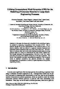
The home made air conditioner was designed and constructed by a Canadian Geoffrey Milburn in 2006, during the course of an extreme hot weather condition in Canada. [1]
Figure 1 Home made portable air conditioner The evaporator unit consists basically of cooling coil primary copper
1" 4
wounded around a fan as shown in figure 1.The
working principle, Design and construction was given detailed out in [1] The evaporative compartment remains one of the most important parts of any cooling system unit. The study of combined fluid flow and heat transfer inside tubes is a Fundamental problem in convective heat transfer. ————————————————
• Ashaju Abimbola is currently pursuing masters degree program in mechanical engineering in Universityof ibadan , Nigeria, • PH-+234(0)8062302107. • E-mail:
[email protected]
Laminar convective heat transfer has found application in many works by several authors [2] [3] [4] [5] [6] [7]. Baron et al. [2] investigated the phenomenon of fully developed and developing laminar flows of a Newtonian fluid between parallel plates and through circular tubes. Sarma et al. [3]Suggested a method, to estimate the heat transfer coefficients in the entry region, of a short length of tube under developing laminar flow conditions. Zhuo et al [4].performed 3D numerical simulations of the laminar flow and heat transfer in silicon microchannels of non-circular cross sections. Edalati et al.[8] Obtained a 41% enhancement in the convective heat transfer coefficient for a 0.8% 𝐶𝐶𝐶/𝑊𝑊𝑊𝑊𝑊 nanofluid after studying the heat transfer of an equilateral triangular duct. The aim of this study is to apply numerical computation in understanding the laminar convective heat flow phenomena within the coiling coil of the home made air conditioner, with the simulation and modelling through the application of COMSOL MULTIPHYSICS.
2 GOVERNING EQUATIONS 2.1 Laminar Convective Fluid and Heat Flow The governing equations for the laminar flow within the cooling coil are 1.
Conservation of mass [continuity equation]
2.
Conservation of momentum [Navier-stokes equation]
3.
Conservation of Energy.
IJSER © 2015 http://www.ijser.org
International Journal of Scientific & Engineering Research, Volume 6, Issue 6, June-2015 ISSN 2229-5518
These equations are summarized below as;
2.2 𝜕𝜌 𝜕𝑡
Continuity equation
𝜕𝜌 𝜕𝑡
+
𝜕𝑡
2.3 𝜕
𝜕(𝜌𝑢) 𝜕𝑥
+
𝜕(𝜌𝑣) 𝜕𝑦
+
𝜕(𝜌𝑤) 𝜕𝑧
(2.2.3)
=0
Navier-Stoke’s Equation (2.3.1)
[𝜌𝑣⃗] + ∇. (𝜌𝑣⃗𝑣⃗) = −∇𝑝 − ∇𝜏̿ + 𝜌𝑔⃗ 𝜕𝑣�⃗
(2.3.2)
𝜌 � 𝜕𝑡 + (𝑣⃗. ∇)𝑣⃗� = −∇𝑝 − ∇𝜏̿ + 𝜌𝑔⃗ 𝜌
3 NUMERICAL MODELS A 3D domain which was a section of the cooling coil was created, with height 20𝑚𝑚 and radius5𝑚𝑚 as shown in Figure 2 below
(2.2.2)
+ ∇(𝜌𝑣⃗) = 0
𝜕𝜌
𝜕𝑡
(2.2.1)
+ 𝜌(∇. 𝑣⃗)=0
261
𝜕𝑣�⃗ 𝜕𝑡
(2.3.3)
= −∇𝑝 − ∇𝜏̿ + 𝜌𝑔⃗
2.4 Energy Equation 𝜌𝐶𝑝
𝑑𝑇 𝑑𝑡
= −∇𝑞⃗ +
𝑑𝑝 𝑑𝑡
+ 𝜏̿. ∇𝑣⃗
2.5 Newton’s law of cooling 𝑞̇ 𝑐𝑜𝑛𝑣 = ℎ[𝑇𝑠 − 𝑇∞ ]
𝑊/𝑚2
3.1 Meshing
(2.5.1)
𝑇𝑠 = 𝑆𝑆𝑆𝑆𝑆𝑆𝑆 𝑡𝑡𝑡𝑡𝑡𝑡𝑡𝑡𝑡𝑡𝑡 𝑇∞ = Temperature of the fluid Fourier's Law of conduction 𝜕𝑇 𝑞 = −𝑘 𝜕𝑥
2.6 Nusselt Number 𝐍𝐮 𝒒̇ 𝒄𝒐𝒏𝒗
𝒒̇ 𝒄𝒐𝒏𝒅
𝑁𝑢 =
=
ℎ𝐿
𝒉∆𝑻 ∆𝑻 𝒌 𝒉
=
The material used for the cooling coil was copper, while the working fluid was chilled water which was considered Newtonian and incompressible. The physics considered was conjugate Heat transfer, which was a mixture of convective heat and Laminar fluid flow. No-slip condition was imposed at the walls of the tube. At the inlet of the tube section, a Laminar inflow boundary condition was adopted, with a flow rate of 0.15 m3 ⁄s .At the outlet of the tube section, zero pressure condition was imposed. An external fan was imposed at the outer of the cooling coils, to provide forced convection effect, whose static pressure curve was linear, with a free delivery flow rate of 0.01 m3 ⁄s.
IJSER (2.4.1)
𝜕𝜕 𝑇 𝜕𝜕 𝜕𝜕 + (𝑢. ∇)𝑇 � = −(∇. 𝑞) + 𝜏. 𝑠 − � + (𝜇. ∇)ρ� 𝜕𝜕 𝜌 𝜕𝜕 𝜕𝜕 (2.4.2) The major mode of heat transfer under study is convection. 𝜌𝐶𝑝 �
Figure 3 Schematic of the Tube section from the cooling coil
𝒉𝒉 𝑲
This was done using coarse free tetrahedral shape with element size ranging from 0.0014 − 0.01, refinements were done at corners with an element scale sizing factor of 0.35 . The features of the meshing are: Number of vertex elements: 8 Number of edge elements: 36 Number of boundary elements: 128 Number of elements: 150. The meshed tube section is shown below in Figure 3
(2.5.2)
(2.6.3)
𝑘
————————————————
• Ashaju Abimbola is currently pursuing masters degree program in mechanical engineering in Universityof ibadan , Nigeria, PH+234(0)8062302107. E-mail:
[email protected]
IJSER © 2015 http://www.ijser.org
International Journal of Scientific & Engineering Research, Volume 6, Issue 6, June-2015 ISSN 2229-5518
262
Figure 4 Meshed Tube section
4 RESULTS AND DISCUSSION The Laminar Convective heat effect within the cooling coil is discussed. As mentioned previously the flow inside the pipe is laminar.The Velocity and Temperature profile for the fluid within the tube section was computed as shown in Figure four and Figure five below. Figure four shows the computed velocity plot for the flow of chilled water within the tube section, as heat exchange takes place between the fluid and the ambient air with channel wall acting as an intermediary
Figure 6 Temperature profile within the tube section
5 CONCLUSION
Numerical investigation of laminar convective heat and fluid flow has been investigated within a tube section, with the aid of COMSOL MULTIPHYSICS. The inlet showed the temperature of the chilled water before heat exchange and the outlet temperature showed the temperature of the chilled water after heat exchange and energy transport. More work still needs to be done to investigate the fluid flow and heat transfer process within the cooling coil of the evaporator. As a perspective, it would be interesting to investigate further, the pressure drop and heat transfer rate of the cooling coils, likewise also the effects of the flow rate on the heat transfer rate.
IJSER ACKNOWLEDGMENT
The author wish to thank Geoffrey Milburn, who provided the platform to work on his portable air-conditioing unit
REFERENCES
1. Prediction of flow pattern and velocity distribution in pipe lines,using COMSOL MULTIPHYSICS simulator. Nasser,
Figure 5 Velocity profile for the flow within the tube section
The temperature field obtained from the simulation ,is presented in Figure 5. A cold zone is observed at the inlet of the tube section where chilled water enters.This is followed by a reduction in the temperature of the fluid at the warm zone. This happens as a temperature gradient is established between the chilled water and the ambient air surrounding the cooling coils. The exchange of heat takes place and the temperature of the working fluid increases from 276𝐾 (3° 𝐶) 𝑡𝑡 292𝐾 (19° 𝐶).
Saghatoleslami and Okhovat, Ahmad. Kermanshah : s.n. Iranian National Chemical Engineering Congress. pp. 1-10. 2. Jakob, Munch Jensen. Dynamic modelling of Thermo-fluid systems with focus on evaporators for refrigeration. Department of Mechanical Engineering, Technical University of Denmark. 2003. Ph.D Thesis. 3. Computational fluid Dynamics [CFD] simulation to analyse the performance of tube-in-tube helically coiled of a heat exchanger. Chaves, C. A, et al. 7, s.l. : Scientific Research and Essays, 2014, academic journals, Vol. 9, pp. 181-188.
IJSER © 2015 http://www.ijser.org
International Journal of Scientific & Engineering Research, Volume 6, Issue 6, June-2015 ISSN 2229-5518
4. CFD Investigation of Heat Transfer and Flow Patterns in Tube Side Laminar Flow and the Potential for Enhancement. Osley, G. William, Droegemueller, Peter and Ellerby, Peter. s.l. : The Italian Association of Chemical Engineering, 2013, CHEMICAL ENGINEERING TRANSACTIONS, Vol. 35. 5. Modelling and Optimization of Heat Transfer in Smooth Circular Tube Used in the Shell and Tube Evaporator. RANJ, SIRWAN, et
𝐶𝑝 𝑣
-
263
Specific Heat Capacity (𝐽⁄(𝑘𝑘. 𝑘))
Viscous Stress Tensor (𝑃𝑃)
Q - Heat Source [𝑊⁄𝑚3 ]
al. Recent Advances in Fluid Mechanics, Heat & Mass Transfer and Biology. 6. Modeling Convective Heat Transfer under Laminar Flow of a Newtonian Fluid in Simple Geometries. Baron, B. and Gutierrez, E. Miravete. Boston : s.n., 2007. Excerpt from the Proceedings of the COMSOL Conference. 7. A novel method to determine laminar convective heat transfer in the entry region of a tube. Sarma, P. k, et al. s.l. : Elsevier, 2003, International Journal of Thermal Sciences, Vol. 43, pp. 555–559.
IJSER
8. A numerical study of laminar convective heat transfer in
microchannel with non-circular cross-section. Zhuo, Li, WenQuan, Tao and Ya-Ling, He. s.l. : ELSEVIER, 2006,
International Journal of Thermal Sciences, Vol. 45, pp. 1140– 1148.
9. Laminar convective heat transfer and pressure drop in the corrugated channels. Paisarn, Naphon. s.l. : ELSEVIER,
International Communications in Heat and Mass Transfer, Vol. 34, pp. 62–71.
10. The Study of Laminar Convective Heat Transfer of CuO/Water Nanofluid Through an Equilateral Triangular Duct at Constant wall heat flux. Edalati, Z., Heris, S. Zeinal and Noie, S. H. 5, s.l. : Wiley Periodicals, Inc., 2012, Heat Transfer—Asian Research, Vol. 41, pp. 1-12.
NOMENCLATURE CFD – Computational Fluid Dynamics CuO – Copper(II) Oxide 𝜌
U T
- Density (𝐾𝐾⁄𝑚3 )
- Velocity Vector (𝑚⁄𝑠) -
Absolute temperature (𝑘)
IJSER © 2015 http://www.ijser.org