Mar 25, 2007 - is higher than the threshold value, the neuron fires. The training algorithm of the basic BNN is as follows. Input: A set of training vectors. K. kA.
IJCSNS International Journal of Computer Science and Network Security, VOL.7 No.3, March 2007
67
Design and Implementation of FPGA-Based Modified BKNN Classifier Jihong Liu†
Baorui Li††
Deqin Liang†††
†
College of Information Science and Engineering, Northeastern University, Shenyang, 110004 China College of Information Science and Engineering, Northeastern University, Shenyang, 110004 China ††† College of Information Science and Engineering, Northeastern University, Shenyang, 110004 China ††
Summary Artificial Neural Network (ANN) is an important tool for Pattern Recognition in Artificial Intelligence field. In this paper, we presented a hardware implementation of ANN based on modification of Boolean k-nearest neighbor (BKNN) classifier proposed by Gazula and Kabuka. BKNN is a kind of supervised classifier using Boolean Neural Network, which has binary inputs and outputs, integer weights, fast learning and classification, and guaranteed convergence. The emphasis of this design is that it is implemented on Field Programming Gate Array (FPGA) chip through Verilog HDL codes programming so that the classifier can be more convenient to be carried and reconfigurable. The satisfying experimental results demonstrate that the modified version of BKNN is characteristic with fast, robust classification ability. It offers the Artificial Intelligence a significant tool in both computer vision and pattern recognition.
Key words: FPGA, Artificial Neural Network, Boolean k-nearest neighbor
1.Introduction 1.1 Artificial Neural Network (ANN) A Neural Network can be defined as “a parallel, distributed information processing structure consisting of processing elements (which can possess local memory and can carry out localized information processing operations) interconnected via unidirectional signal channels called connections” [1]. ANN becomes more and more popular in the Artificial Intelligence (AI) field these decades since it can be used for image processing, pattern recognition, fingerprint analysis and many other problems’ solving. It has many advantages over other approaches for better tolerance, parallel processing, high speed and strong self-learning ability. Nowadays, feed forward ANN has the widest and most comprehensive application among all the ANN models. Backpropagation Neural network (BPNN) is a typical feed forward structure. Nonetheless, there are no definite rules for the choice of how many hidden layers Manuscript received March 5, 2007 Manuscript revised March 25, 2007
and neurons, no promising convergence and it may take very long time for the iterative training procedures. Zhou Linxia, Li Ming, and Liu Gaohang et al. designed a feed forward ANN utilizing genetic algorithm for writer identification of text-independence [4]. As shown in [11], X. Li, S. Bhide, and M.R.Kabuka have applied ANN for segmenting magnetic resonance brain images. An FPGA-based hardware evaluation system for use with genetic-algorithm-designed ANN was proposed by Earl [5]. Basing on the preceding researches, we search for an appropriate settlement for the computer vision and pattern recognition use. The practical experimental results of the above designs demonstrate that an appropriate neural network implemented by FPGA could be an excellent tool for computer vision and pattern recognition.
1.2 Field Programming Gate Array (FPGA) According to the natural features of Neural Network, the hardware implementation is superior to the software approach because it can take advantage of ANN’s characteristics, especially parallelism. Furthermore, since FPGA is a digital device with reconfigurable properties and robust flexibility, many researchers have made great efforts on the realization of ANN using FPGA technique [2] [3]. However, they encountered many problems during the process. It is hard to design a learning algorithm for FPGA implementation with appropriate frequency, precision, parallelism and configuration. ANN using pulse-mode architecture is under research during these years, as pulse-mode signals are easy to handle. Hikawa has proposed several kinds of pulse-mode neurons with different activation functions and pulse modulation [6] [7]. Although they are able to meet some requirements, the experiments of Hikawa show that the operating speed and circuit size are not satisfactory.
IJCSNS International Journal of Computer Science and Network Security, VOL.7 No.3, March 2007
68
2. Boolean Neural Network (BNN) 2.1. Basic BNN A novel BNN has been developed in [8] and [9]. The network consists of two layers of neurons in a feed forward structure. These neurons are fully connected between layers as shown in Fig. 1.
presented in [11]. Also, BNN has been modified to include the iterative procedure for solving the famous Traveling Salesman Problem [12]. The three most important features of the supervised pattern classifiers are guaranteed convergence, ease of training of a new exemplar without a lengthy unlearning phase, and binary weights and integer threshold values which make easier implementation in hardware and faster computations [10].
O utputs
2.2.Supervised Classifier Using BNN
O utpu ts layer
E xem plar nodes
I2
I1
In
Inputs
Fig. 1 The topology of the basic BNN
The input vector of the network has each element connected to the neuron with a corresponding weight. These weights are dependent on the inputs. Each neuron performs a weighted sum by multiplying the binary-valued inputs with the bipolar-valued weights. If the inner product is higher than the threshold value, the neuron fires. The training algorithm of the basic BNN is as follows. Input: A set of training vectors Ak , k = 1,2,L, K ; when K is the number of training vectors. Step 1: Accept Ak = [a1k , a2 k , L , ank ] , aik ∈ {0,1} where aik , i = 1,2, L , n are parameters associated with Ak . Step 2: Calculate Wk = [ w1k , w2 k , L , wnk ] , wik ∈ {−1,1} Wk is the weight vector associated with Ak . Step 3: Set the k th neuron’s threshold as Tk =
∑a w ik
ik
Neareast-to-an-examplar (NTE) supervised classifier memorizes the exemplars or the representative sample for each class during the training phase. It classifies an input pattern to an exemplar with a smallest metric Hamming distance. Boolean k-nearest neighbor classifier takes the following procedures to classify a pattern. Let N be the number of training patterns that are denoted as: X ((li)) , i = 1,2,L, N l , l = 1,LC , where
training patterns from class l ,
is the number of
C
∑ Nl = N
and C is the
l =1
total number of categories. Given an input pattern X ((li)) the k-nearest neighbor decision rule δ ( X ) = ωi , if K i (k , N ) ≥ K j (k , N ), ∀j ≠ i Where K i (k , N ) is the number of patterns from class ωi among the k-nearest neighbor of pattern X ((li)) . The architecture of the network is shown in Fig. 2 and the algorithm for Boolean k-nearest neighbor classifier is as follows. ambiguity node(T=2) 1
(1)
i
Step 4: Repeat ∀ Ak by going back to Step 1. Outputs: A set of weight vectors Wk and neuron thresholds Tk . Since the output is Boolean, the link with modern digital computer is obvious. Basing on the preceding training algorithm, BNN can alter its threshold to make itself adaptive to the pattern by introducing the concept of Radius of Attraction (ROA). All patterns that differ from the stored pattern with a distance of rk and less succeed in firing the corresponding neuron. Thus the training of BNN is implemented by the memorization of the training vectors and generalization is implemented by the ROAs. Two supervised pattern classifiers using BNN were proposed by Gazula and Kabuka in 1995, namely the nearest to an exemplar (NTE) classifier and Boolean k-nearest neighbor (BKNN) classifier [10]. A knowledge-based approach for labeling two-dimensional magnetic resonance brain images using BNN was
Nl
CA -1
1 1
CR distance rejection node (T=0) -1 -1 class nodes(Tc=1)
1
1 1
1
1
S1N1
S11
1
2
1
1
1
1 1
1 1
ScNc
Sc1
training nodes
n
input units
Fig. 2 Boolean k-nearest neighbor classifier (binary feature values)
Training processing: Step 1: Create the network with three layers as follow: (i) N nodes Sil in the first layer labeled in the same order as the training patterns, i = 1,2, L , N l , l = 1, L C . (ii) C nodes in the second layer and labeled as Cl ,
IJCSNS International Journal of Computer Science and Network Security, VOL.7 No.3, March 2007 l = 1, L C to present the classes.
(iii)A third layer consisting of the rejection node C R and the ambiguity node C A . Step 2: The weights and thresholds for the network are setup as below. (i) Present the training pattern X ((li)) . Calculate the weight vector Wil for nodes Sil as described in algorithm of Fig. 2. The threshold of the same is set as Til = X ((li)) ⋅Wil − k , where k is the parameter that governs the nearness of the patterns. Repeat this step for all training patterns. (ii) Connect node Cl to the nodes Sil , i = 1,2, L , N l . In other words node Cl representing the class l connects all nodes in the first layer representing the training patterns belonging to the same class. The weights of all the connections are set to 1 and the thresholds of Cl , Tc (common to all class nodes) are set to 1. (iii) The ambiguity node C A is connected to the class nodes with unit weights and its threshold is set at 2. The rejection node C R is connected to the class nodes with weights -1 and its threshold is set to 0. Classification: The classification of an input pattern takes place as follows: (i) Present the pattern to the network. (ii) If C R is on then the pattern to rejected. Go to (vi). (iii) Increment the threshold Tc of Cl , l = 1, L C by one. (iv) If C R is on then go to (v), else go to (iii). (v) Decrement the threshold Tc by one and read the labels of the units in the second layer which are on. The input pattern belongs to the corresponding class or classes (ambiguous). (vi) Reset the thresholds of the second layer nodes to 0 for further pattern classification. There are some controversies on these two supervised pattern classifiers about one-to-one correspondence between exemplars, nodes, and classes and unclear or inaccurate algorithm in some particulars [10]. Nonetheless, the binary neural networks described by Gazula and Kabuka, are worthy of investigation [13]. These classifiers use the concept of ROA to achieve their goal. The BNN classifiers have been proven to have superior capacity compared to the Hopfield nets, Hamming and PACNET networks.
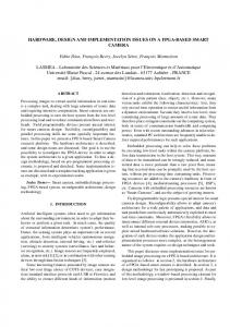
3. A Modified BKNN After a comprehensive mathematical analysis, we realized that the training pattern belongs to the class connected with the Sil training node whose difference between the
69
inner product T1 and the predetermined threshold T is the greatest. CA ambiguity node(T=2) 1 1
class CR node(T=0) distance rejection node -1 -1 (T=0) 1 -1
Csgn 1 1 1
class nodes(Tc=0) 1
1 1
1
1
S1N1
S11
1
2
1
1
1
1 1
1 1
ScNc
Sc1
training nodes
n
input units
Fig. 3 The topology of the modified BKNN
Most of the training rules are the same to the former design as described in the above section. We have made some modifications shown below. First, the thresholds Tc of the class neurons in the second layer are set at 0. Therefore, the class neuron needs only to accomplish the accumulation of the weighted inputs. Second, one more neuron has been added in the third layer--the sign neuron Csgn . All of its weights are set at 1. When our classifier accomplishes its task, the result comes out. There are three possibilities. First, the tested pattern is rejected if the reject neuron C R fires; second, the tested pattern may belong to ambiguous classes if the ambiguous neuron C A fires; otherwise, it must definitely belong to one of the classes. The network needs one more neuron to demonstrate the specific class that the tested pattern belongs to. The classification algorithm of the modified BKNN is presented below. (i) Present the test pattern X to the network. (ii) Compare T1 with T . Cnl is a vital value for our design. It is calculated according to the relationship between T1 with T by the training node Sil . T1 is the inner product of the current inputs and predetermined weights, and T is the predetermined threshold. a. T1 < T , Cnl ⇐ 0 ; b. T1 = T , Cnl ⇐ 1 ; c. T1 > T , Cnl ⇐ (n + 1) k , where k = T1 − T ( k ≥ 1 ), n is the greatest number of training nodes Sil connecting to a certain class node, so n ≥1. Proof. Assumed all the training nodes belonging to the class that has the greatest number of training nodes Sil are fired, i.e., each training node Sil has T1 > T , k = T1 − T , their K = [ k1 , k 2 , L , k n ] , while km is the greatest
IJCSNS International Journal of Computer Science and Network Security, VOL.7 No.3, March 2007
70
value. Another class has only one training node fired, however, it has got an Sil whose k = k m + α , α is an integer, greater than zero. Now, we have to verify that the class connected with the Sil whose k = k m + α will beat other classes. We will strengthen the punishment of the classes whose Sil neurons don’t obtain the greatest difference between T1 and T . In other words, it is an award for the Sil which get the greatest k = T1 − T value. ( n + 1) k1 ≤ ( n + 1) km ( n + 1) k2 ≤ ( n + 1) km ( n + 1)
kn
M
≤ ( n + 1) km
node fires. The input pattern belongs to the corresponding classes (ambiguous). As we present, the modified algorithm has omitted the iterative classification procedure of the former architecture shown in Fig. 3. The network needs only one-shot learning and a single classification sweep to obtain the answer. Compared with the former BKNN in the aspect of algorithm, its advantages become more and more obvious with ROA turning greater, because there are no more iteration steps. Additionally, the processing speed of FPGA chip is far higher than the software implementation approach.
4. Results
So, we get ( n + 1) k1 + ( n + 1) k2 + L + ( n + 1) km −1 + (n + 1) km + (n + 1) km +1 + L + ( n + 1) kn ≤ ( n + 1) km + L + ( n + 1) km = n ⋅ (n + 1) km (n + 1) k1 + (n + 1) k2 + L + (n + 1) kn ≤ n ⋅ (n + 1) km
(2)
We will prove n ⋅ (n + 1) k < (n + 1) k +α
(3) Proof. According to the Mathematical Induction, Q when α = 1 , n ⋅ (n + 1) k < (n + 1) k +α = (n + 1)(n + 1) k . Assumed, when α = b , functional inequality (3) is valid, i.e., n ⋅ (n + 1) k < (n + 1) k +b . And n ⋅ ( n + 1 ) < ( n + 1 ) ⋅ (n + 1) = (n + 1) n ⋅ (n + 1) k < (n + 1) k +b +1 , so when α = b + 1 , functional inequality (3) is also valid. ∴ Functional inequality (3) is valid for all the possibilities. Binding (2) and (3), we get k
k + b
k + b +1
(n + 1) k1 + (n + 1) k 2 + L + (n + 1) k n ≤ n ⋅ (n + 1) k m
(4)
< (n + 1) k m +α
So we can promise training node Sil which gets the greatest k = km + α would beat all the other nodes and win. (iii) Accumulating the Cnl of Sil that connect to one class node Cl , we get Cn , i.e., C n = ∑ C nl . (iv) First, we calculate C =
∑C
l
n
Verilog HDL is the programming language utilized to carry out the design. The platform on which we designed this neural network is ISE 6.0 version of Xilinx. We choose XC2S100E as our target chip. XC2S100E is one of device types of Spartan2E device family developed by Xilinx company. The modified BKNN was tested with data sets that are denoted by 64 binary feature values. The test results are satisfying. The modified BKNN could classify 95% of the patterns with distortions as high as 45%. Its performance is better than the former design. Any pattern that is denoted with binary feature values can be applied to this classifier. We have tested a group of binary character patterns, numeric patterns and a serial of digital images. Furthermore, this classifier can be extended to recognize a pattern that owns more than 64 binary features. It will be our future task. Though we haven’t taken the continuous feature values into account in this paper, we have understood its design principle [10]. Through a serial preceding processing for the continuous values, they can be turned into binary values after certain coding approach. The results obtained are encouraging and comparable with those obtained with existing neural network classifiers.
5. Conclusions
, and judge the value
n
of C . a. C = 0 , ∑ −1 ⋅ C = 0 , therefore C R node fires. b. C ≠ 0 , we have to find the greatest value Cm among Cn , n = 1,2, LC . There are two possibilities. (a) There is only one Cm . The modified BKNN classifies a test pattern X to class ωm , m ∈ {1,2, L C} if and only if Cm > Cn , ∀m ≠ n . Csgn fires. Meantime, Csgn sends the class number m of Cm class neuron in
the class layer. (b) If Cm ≥ Cn , i.e., there are more than one Cm , C A
As we know, many traditional neural network classifiers require iterative cycles for learning. The network must converge before being able to be used. The pattern classifier proposed in this paper is trained in one-shot and can perform classification straight forward without iterative procedures. We have observed that the distances among the classes can affect classification results. So we can not judge the performance only by the distortions of the patterns, but also the distance among the classes. Larger distances among easily separable classes can be entitled with greater distortions while testing. FPGAs are reprogrammable digital ICs. Architecture
IJCSNS International Journal of Computer Science and Network Security, VOL.7 No.3, March 2007
implemented on FPGA chip is reconfigurable [14] [15]. Therefore, the modified BKNN pattern classifier is more flexible than other hardware realization. The modified classifier presented above is simple and robust. The advantages of the modified BKNN include a single training and classification sweep, guaranteed convergence, and simple neuron architecture. This network design is superior to most of the neural networks for its fault tolerance ability. In addition, this modified BKNN pattern classifier costs effectively and leads to a lot of savings in area, time and money. This hardware realization can be embedded into systems for wider and more comprehensive application. It can be favorably made to suit particular pattern recognition system needs and thus it makes the system more convenient to be carried and open for further development.
[11]
[12]
[13]
[14]
71
Trans. On Pattern Analysis and Machine Intelligence, Vol. 17, No. 12, Dec. 1995 Xiaohong Li, Shirish Bhide and M.R. Kabuka, Labeling of MR Brain Image Using Boolean Neural Network, IEEE Trans. on Medical Imaging. Vol. 15, No. 5, Oct. 1998 Shirish Bhide, Nigel John and M. R. Kabuka. A Real -Time solution for the Traveling Salesman Problem using a Boolean Neural Network, IEEE Transactions on Computer, Vol. 42, pp. 1271-1278, Oct. 1993 Guy Smith. Comments on “Design of Supervised Classifiers Using Boolean Neural Neworks”, IEEE Transactions on Pattern Analysis and Machine Intelligence, Vol. 21, No. 9, Sept. 1999 Zh. Wang and E. Zhu, VLSI design, Beijing: Publishing House of Electronic Industry, pp. 75–92, 2005.
References [1]
Robert Hecht-Nielsen, "Neurocomputing," Addison-Wesley Publishing Company, Inc., 1990. [2] Jihong Liu, Deqin Liang. A Survey of FPGA-Based Hardware Implementation of ANNs , IEEE Proceedings of 2005 International Conference on Neural Networks & Brain(ICNN&B’05) , Vol. 2, pp.915-918. Oct.13-15, 2005. [3] K. R. Nichols, M. A. Moussa and S. M. Areibi, “Feasibility of Floating Arithmetic in FPGA Based Artificial Neural Networks”, Transaction of School of Engineering University of Guelph, Ontario, 2003. [4]Zhou Linxia, Li Ming, Liu Gaohang and Yang Xiaoqin. A writer identification of text-Independent based on feed-forward neural network, Jounal of Nanchang Institute of Aeronautical Technology (Natural Science), Vol. 16, No.1, Mar., 2002 [5] D. D. Earl, Development of an FPGA-based Hardware Evaluation System for Use with GA-designed Artificial Neural Networks, May 2004. [6] H. Hikawa, “A Digital Hardware Pulse-Mode Neuron with Piecewise Linear Activation Function,” IEEE Trans. Neural Network, vol. 14, pp.1028-1037, Oct.2003. [7] H. Hikawa, “A Multilayer Neural Network with Pulse Position Modulation,” Systems and Computers in Japan, Vol. 34, No. 13, 2003. [8] B.Hussain, M.R.Kabuka. Neural net transformation of arbitrary Boolean functions, SPIE 1992Int. Symp. Optical and Applied Science: Neural and Stochastic methods in Image and Signal Processing, pp. 0060-0061, 1992 [9] B.Hussain, M.R.Kabuka. A novel feature recognition neural network and its application to character recognition, IEEE Trans. Pattern Anal. Machine Intell., vol. 16, no1, pp. 98-106, Jan. 1994 [10] S.Gazula and M.R.Kabuka. Design of Supervised Classifiers Using Boolean Neural Networks, IEEE
Jihong Liu received the B.E. and M.E. degrees, from Northeastern University and China Medical University in 1991 and 1994, respectively. She received the Dr. Eng. degree from Northeastern Univ. in 2003. After working as an assistant (from 1994), a lecturer (from 1997), she is an assistant professor (from 2002) in the college of information science and engineering, Northeastern University. Her research interest includes digital signal processing, intelligent information processing.
Baorui Li received the B.E. degree from Shandong University in 2005. He is now studying as a postgraduate student in Northeastern University. His research interest
includes Electronic Circuits design, SOC (System On Chip) and Artificial Intelligence. He is now working on FPGA-based Artificial Neural Network and Biological Computing.
Deqin Liang
received the B.E. and M.E. degrees, from Norteastern University in 2004 and 2007, respectively. Her research interest includes Artificial Intelligence, especially Artificial Neural Network, and Electronic Engineering, especially PLD, FPGA.