This article has been accepted for inclusion in a future issue of this journal. Content is final as presented, with the exception of pagination. IEEE TRANSACTIONS ON VERY LARGE SCALE INTEGRATION (VLSI) SYSTEMS
1
Design of Testable Reversible Sequential Circuits Himanshu Thapliyal, Student Member, IEEE, Nagarajan Ranganathan, Fellow, IEEE, and Saurabh Kotiyal, Student Member, IEEE Abstract— In this paper, we propose the design of two vectors testable sequential circuits based on conservative logic gates. The proposed sequential circuits based on conservative logic gates outperform the sequential circuits implemented in classical gates in terms of testability. Any sequential circuit based on conservative logic gates can be tested for classical unidirectional stuck-at faults using only two test vectors. The two test vectors are all 1s, and all 0s. The designs of two vectors testable latches, master-slave flip-flops and double edge triggered (DET) flip-flops are presented. The importance of the proposed work lies in the fact that it provides the design of reversible sequential circuits completely testable for any stuck-at fault by only two test vectors, thereby eliminating the need for any type of scan-path access to internal memory cells. The reversible design of the DET flip-flop is proposed for the first time in the literature. We also showed the application of the proposed approach toward 100% fault coverage for single missing/additional cell defect in the quantumdot cellular automata (QCA) layout of the Fredkin gate. We are also presenting a new conservative logic gate called multiplexer conservative QCA gate (MX-cqca) that is not reversible in nature but has similar properties as the Fredkin gate of working as 2:1 multiplexer. The proposed MX-cqca gate surpasses the Fredkin gate in terms of complexity (the number of majority voters), speed, and area. Index Terms— Cellular automata, conservative logic, Fredkin gate, quantum-dot, reversible logic.
I. I NTRODUCTION ONSERVATIVE logic is a logic family that exhibits the property that there are an equal number of 1s in the outputs as there are in the inputs. Conservative logic can be reversible in nature or may not be reversible in nature. Reversibility is the property of circuits in which there is oneto-one mapping between the inputs and the output vectors, that is for each input vector there is a unique output vector and vice-versa. Conservative logic is called reversible conservative logic when there is a one-to-one mapping between the inputs and the outputs vectors along with the property that there are equal number of 1s in the outputs as in the inputs. Conservative logic circuits are not reversible, if one-to-one mapping between the inputs and the outputs vectors is not preserved. Researchers have proved that if the computation is performed in an irreversible manner, each bit of information lost will produce KTln2 Joules of heat energy. From a thermodynamic point of view, it is also proved that kTln2 energy dissipation would not occur, if a computation is carried out in
C
Manuscript received July 15, 2011; revised March 7, 2012; accepted April 22, 2012. The authors are with the Department of Computer Science and Engineering, University of South Florida, Tampa, FL 33620 USA (e-mail:
[email protected];
[email protected];
[email protected]). Color versions of one or more of the figures in this paper are available online at http://ieeexplore.ieee.org. Digital Object Identifier 10.1109/TVLSI.2012.2209688
(a)
(b)
(c)
(d)
(e)
(f) Fig. 1. QCA cell and basic QCA devices. (a) QCA 4 Dots. (b) QCA cell as logic “1,” and logic “0.” (c) MV. (d) Inverter (INV). (e) Binary wire. (f) INV chain.
a reversible way. There are emerging nanotechnologies, such as quantum-dot cellular automata (QCA) computing, optical computing, and superconductor flux logic family, etc., where the energy dissipated due to information destruction will be a significant factor of the overall heat dissipation of the system [1], [2]. Thus, one of the primary motivations for adopting reversible logic lies in the fact that it can provide a logic design methodology for designing ultralow power circuits beyond KTln2 limit for those emerging nanotechnologies in which the energy dissipated due to information destruction will be a significant factor of the overall heat dissipation. Further, QCA is one of the emerging nanotechnologies in which it is possible to implement reversible logic gates [2], [3]. QCA makes it possible to achieve circuit densities and clock frequencies beyond the limits of existing CMOS technology [4], [5]. In QCA, computing logic states of 1 and 0 are represented by the position of the electrons inside the QCA cell as illustrated in Fig. 1(b). Thus, when the bit is flipped from 1 to 0 there is no actual discharging of the capacitor as in conventional CMOS. Hence, QCA does not have to dissipate all its signal energy during transition. Further, propagation of the polarization from one cell to another is because of interaction of the electrons in adjacent QCA cells. As there is no movement of electrons from one QCA cell to the other, there is no current flow. Thus, QCA has no dissipation in
1063–8210/$31.00 © 2012 IEEE
This article has been accepted for inclusion in a future issue of this journal. Content is final as presented, with the exception of pagination. 2
IEEE TRANSACTIONS ON VERY LARGE SCALE INTEGRATION (VLSI) SYSTEMS
signal propagation. Therefore, QCA has significant advantage compared to CMOS technology in terms of power dissipation. Due to high error rates in nano-scale manufacturing, QCA and other nanotechnologies target reducing device error rates [6]. In this paper, we propose the design of testable sequential circuits based on conservative logic gates. The proposed technique will take care of the fan-out (FO) at the output of the reversible latches and can also disrupt the feedback to make them suitable for testing by only two test vectors, all 0s and all 1s. In other words, circuits will have feedback while executing in the normal mode. However, in order to detect faults in the test mode, our proposed technique will disrupt feedback to make conservative reversible latches testable as combinational circuits. The proposed technique is extended toward the design of two vectors testable master-slave flipflops and double edge triggered (DET) flip-flops. Thus, our work is significant because we are providing the design of reversible sequential circuits completely testable for any unidirectional stuck-at faults by only two test vectors. The reversible design of the DET flip-flop is proposed for the first time in the literature. Further, we implemented the Fredkin gate in the QCA technology and observed that all 0s and all 1s test vectors cannot provide 100% fault coverage for single missing/additional cell defect in the QCA layout of the Fredkin gate. Thus, to have the 100% fault coverage for single missing/additional cell defect by all 0s and all 1s test vectors, we identified the QCA devices in the QCA layout of the Fredkin gate that can be replaced with fault tolerant components to provide the 100% fault coverage. Further, while designing a QCA sequential circuit, the designer may sometimes prefer to sacrifice the reversibility to save the number of QCA cells while keeping the test strategy to be the same that is the design can still be tested by two test vectors. Thus, we also propose a new conservative logic gate called multiplexer conservative QCA gate (MX-cqca) that is not reversible in nature but has similar properties as the Fredkin gate of working as 2:1 multiplexer. The proposed MX-cqca gate surpasses the Fredkin gate in terms of complexity [the number of majority voters (MV)], speed, and area. This paper is organized as follows. Section II presents the background on conservative logic, the basics of QCA computing, such as QCA logic devices and QCA clocking, related work etc. Section III presents design of testable reversible latches, Section IV describes design of testable reversible master-slave flip-flops, Section V presents design of testable reversible DET flip-flop, Section VI discusses the application of the proposed two vectors, all 0s and all 1s, testing approach to QCA computing, Section VII presents the proposed multiplexer conservative QCA gate, while the design methodology for nonreversible circuits based on MX-cqca gate is discussed in Section VIII, and Section IX provides some discussions and conclusions. II. BACKGROUND A conservative logic gate is a multiple-output logic element in which the number of 1s at the inputs is equal to that of the corresponding outputs. According to [7] and [8], a
conservative logic circuit can be considered as a directed graph whose nodes are conservative logic gates, and the edges are wires of arbitrary lengths. The FO at the output is not allowed in conservative logic circuits. A conservative logic network can be reversible in nature if the one-to-one mapping is maintained between the inputs and the outputs, while it will be irreversible in nature if one-to-one mapping is not preserved. Researchers in [7], [9], and [10] have proved that: 1) in the event of unidirectional stuck-at-faults in a conservative logic network, either the number of 1s in its output set will differ from the number of 1s in its input set, or the output set is correct and 2) in a conservative logic network the two vector test sets, all 1s and all 0s, provide 100% coverage for unidirectional stuck-at faults. Any stuck-at-1 fault in the conservative logic circuit can be detected by setting all inputs to 0s followed by subsequent checking of the outputs for the presence of any 1s. Any stuck-at-0 faults can be detected by setting all inputs to 1s followed by subsequent checking of outputs for the presence of any 0s. The comprehensive proofs can be referred in [7], [9], and [10] A. Conservative Reversible Fredkin Gate The Fredkin gate is a popularly used reversible conservative logic gate, first proposed by Fredkin and Toffoli in [8]. The Fredkin gate shown in Fig. 1 can be described as a mapping (A, B, C) to (P = A, Q = A′ B + AC, R = AB + A′ C), where A, B, C are the inputs and P, Q, R are the outputs, respectively. The truth table for the Fredkin gate is illustrated in [3], which demonstrates that Fredkin gate is reversible and conservative in nature, that is, it has unique input and output mapping and also has the same number of 1s in the outputs as in the inputs. B. Basics of QCA Computing In this paper, the conservative logic gates are implemented in the QCA nanotechnology, thus we are also providing the introductory material on QCA computing. A QCA cell is a coupled dot system in which four dots are at the vertices of a square. The cell has two extra electrons that occupy the diagonals within the cell due to electrostatic repulsion. Fig. 1(a) and (b) shows the four quantum dots in a QCA cell, and the implementation of logic “0” and logic “1” in a QCA cell, respectively. The basic QCA device is the MV or majority gates, which is represented as F = AB + BC + AC, where F is the majority of the inputs A, B, and C. Another important gate in QCA is the INV. There can be many ways of designing the QCA INV, one of which is shown in Fig. 1(d). In QCA computing, signal transfer is made through wires that are of two types: 1) binary wire and 2) INV chain. The binary wire is shown in Fig. 1(e). The INV chain is shown in Fig. 1(f). In QCA, when a binary wire crosses the INV chain, there is no interaction between the two; hence, the signals in the INV chain and binary wire can pass over each other. In QCA computing, the clock helps in the synchronization of circuits and provides the power required for functionality. QCA clocking consists of four phases: switch, hold, release, and relax.
This article has been accepted for inclusion in a future issue of this journal. Content is final as presented, with the exception of pagination. THAPLIYAL et al.: DESIGN OF TESTABLE REVERSIBLE SEQUENTIAL CIRCUITS
3
(a) Fig. 2.
Fredkin gate.
C. Related Work Any nanotechnology having applications of reversible logic, such as based on nano-CMOS devices, NMR-based quantum computing, or low power molecular QCA computing, all are susceptible to high error rates due to transient faults. With respect to this paper on reversible sequential circuits, the design of reversible sequential circuits is addressed in the various interesting contribution in which the designs are optimized in terms of various parameters, such as the number of reversible gates, garbage outputs, quantum cost, delay etc [11]–[13]. To the best of our knowledge, the offline testing of faults in reversible sequential circuits is not addressed in the literature. In this paper, we present the design of reversible sequential circuits that can be tested by only two test vectors, all 0s and all 1s, for any unidirectional stuck-at-faults. Further, the approach of fault testing based on conservative logic is extended toward the design of nonreversible sequential circuits based on MX-cqca. III. D ESIGN OF T ESTABLE R EVERSIBLE L ATCHES The characteristic equation of the D latch can be written as Q + = D · E + E¯ · Q. In the proposed work, enable (E) refers to the clock and is used interchangeably in place of clock. When the enable signal (clock) is 1, the value of the input D is reflected at the output that is Q + = D. While, when E = 0 the latch maintains its previous state, that is Q + = Q. The reversible Fredkin gate has two of its outputs working as 2:1 MUxes, thus the characteristic equation of the D latch can be mapped to the Fredkin gate (F). Fig. 3(a) shows the realization of the reversible D latch using the Fredkin gate. But FO is not allowed in conservative reversible logic. Moreover, the design cannot be tested by two input vectors all 0s and all 1s because of feedback, as the output Q would latch 1 when the inputs are toggled from all 1s to all 0s and could be misinterpreted as stuck-at-1 fault. In this paper, we propose to cascade another Fredkin gate to output Q as shown in Fig. 3(b). The design has two control signals, C1 and C2. The design can work in two modes: 1) normal mode and 2) test mode. 1) Normal Mode: The normal mode is shown in Fig. 3(c) in which we will have C1C2 = 01 and we will have the design working as a D latch without any fan-out problem. 2) Test Mode (Disrupt the Feedback): In test mode, when C1C2 = 00 as shown in Fig. 3(d) it will make the design testable with all 0s input vectors as output T1 will become 0 resulting in making it testable with all 0s input vectors. Thus, any stuck-at-1 fault can be detected. When C1C2 = 11 as shown in Fig. 3(e), the output T1
(b)
(c)
(d)
(e) Fig. 3. Design of testable reversible D latch using conservative Fredkin gate. (a) Fredkin gate based D latch. (b) Fredkin gate based D latch with control signals C1 and C2. (c) Fredkin gate based D Latch in normal mode: C1 = 0 and C2 = 1. (d) Fredkin gate based D latch in test mode for stuck-at-0 fault: C1 = 1 and C2 = 1. (e) Fredkin gate based D latch in test mode for stuck-at-1 fault: C1 = 0 and C2 = 0.
will become 1 and the design will become testable with all 1s input vectors for any stuck-at-0 fault. It can seen from above that C1 and C2 will disrupt the feedback in test mode, and in normal mode will take care of the fanout. Thus, our proposed design works as a reversible D latch and can be tested with only two test vectors, all 0s and all 1s, for any stuck-at fault by utilizing the inherent property of conservative reversible logic. A. Design of Testable Negative Enable Reversible D Latch A negative enable reversible D latch will pass the input D to the output Q when E = 0; otherwise maintains the same state. The characteristic equation of the negative enable D latch is
This article has been accepted for inclusion in a future issue of this journal. Content is final as presented, with the exception of pagination. 4
IEEE TRANSACTIONS ON VERY LARGE SCALE INTEGRATION (VLSI) SYSTEMS
Fig. 4.
Fredkin gate-based negative enable testable D latch.
Fig. 5.
Fredkin gate-based testable reversible master-slave D flip-flop.
Q + = D· E¯ +E ·Q. This characteristic equation of the negative enable reversible D latch can be mapped on the second output of the Fredkin gate as shown in Fig. 4. The second Fredkin gate in the design take cares of the FO. The second Fredkin gate in the design also helps in making the design testable by two test vectors, all 0s and all 1s, by breaking the feedback based on control signals C1 and C2 as illustrated above for positive enable reversible D latch. The negative enable D latch is helpful in the design of testable reversible master-slave flipflops. This is because as it can work as a slave latch in the testable reversible master-slave flip-flops in which no clock inversion is required. The details of which are discussed in the section describing reversible master-slave flip-flops. IV. D ESIGN OF T ESTABLE M ASTER -S LAVE F LIP -F LOPS In the existing literature, the master-slave strategy of using one latch as a master and the other latch as a slave is used to design the reversible flip-flops [13]. In this paper, we have proposed the design of testable flip-flops using the masterslave strategy that can be tested for any stuck-at faults using only two test vectors, all 0s and all 1s. Fig. 5 shows the design of the master-slave D flip-flop in which we have used positive enable Fredkin gate-based testable D latch shown in Fig. 3(b) as the master latch, while the slave latch is designed from the negative enable Fredkin gate-based testable D latch shown earlier in Fig. 4. The testable reversible D flip-flops has four control signals mC1, mC2, sC1, and sC2. mC1 and mC2 control the modes for the master latch, while sC1 and sC2 control the modes for the slave latch. In the normal mode, when the design is working as a master-slave flip-flop the values of the controls signals will be mC1 = 0 and mC2 = 1, sC1 = 0 and sC2 = 1 ( as similar to values of the control signals C1 and C2 earlier described for the testable D latches).
In the test mode. 1) To make the design testable with all 0s input vectors for any stuck-at-1 fault, the values of the controls signals will be mC1 = 0 and mC2 = 0, sC1 = 0 and sC2 = 0. This will make the outputs mT 1 and sT 1 as 0, which results in breaking the feedback and the design becomes testable with all 0s input vectors for any stuck-at-1 fault. 2) To make the design testable with all 1s input vectors for any stuck-at-0 fault, the values of the control signals will be mC1 = 1 mC2 = 1, sC1 = 1, and sC2 = 1. This will result in outputs mT 1 and sT 1 having a value of 1, breaking the feedback and resulting in the design testable with all 1s input vectors for any stuck-at-0 fault. The other type of master-slave flip-flops, such as the testable master-slave T flip-flop, testable master-slave JK flip-flop, and testable master-slave SR flip-flop can be designed similarly in which master is designed using the positive enable corresponding latch, while the slave is designed using the negative enable Fredkin gate-based D latch. For example, in the design of master-slave T flip-flop, the master is designed using the positive enable T latch, while the slave is designed with the negative enable D latch. An example of comparative study is shown in Table I that shows the comparison of proposed reversible sequential building blocks with the existing reversible nontestable sequential building blocks [13] and online testable sequential building blocks [14] in terms of number of gate count, number of constant inputs, and garbage outputs. The number of gate count, number of constant inputs, and garbage output of an online testable sequential building [14] are computed without consideration of IRC blocks used in the designs. V. D ESIGN OF T ESTABLE R EVERSIBLE DET F LIP -F LOPS The DET flip-flop is a computing circuit that samples and stores the input data at both the edges, that is at both the rising and the falling edge of the clock. The masterslave strategy is the most popular way of designing the flip flop. In the proposed work, E refers to the clock and is used interchangeably in place of clock. In the negative edge triggered master-slave flip-flop when E = 1 (the clock is high), the master latch passes the input data while the slave latch maintains the previous state. When E = 0 (the clock is low), the master latch is in the storage state while the slave latch passes the output of the master latch to its output. Thus, the flip-flop does not sample the data at both the clock levels and waits for the next rising edge of the clock to latch the data at the master latch. In order to overcome the above problem, researchers have introduced the concept of DET flip-flops, which sample the data at both the edges. Thus, DET flip-flops can receive and sample two data values in a clock period thus frequency of the clock can be reduced to half of the master-slave flip flop while maintaining the same data rate. The half frequency operations make the DET flip flops very much beneficial for low power computing as frequency is proportional to power consumption in a circuit. The DET flip-flop is designed by connecting the two latches, viz., the positive enable and the
This article has been accepted for inclusion in a future issue of this journal. Content is final as presented, with the exception of pagination. THAPLIYAL et al.: DESIGN OF TESTABLE REVERSIBLE SEQUENTIAL CIRCUITS
5
TABLE I C OMPARISON OF P ROPOSED S EQUENTIAL B UILDING B LOCKS No. of gates No. of constant inputs [14] [13] Proposed [14] [13] Proposed D flip-flop 7 4 4 24 2 4∗ T flip-flop 9 4 5 30 2 5∗ * In different modes of operation (test mode, normal mode) values of ** The garbage outputs will be a useful output in case of test mode. Type
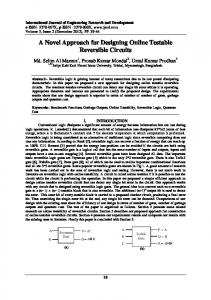
negative enable in parallel rather than in series. The 2:1 MUX at the output transfer the output from one of these latches which is in the storage state (is holding its previous state). The conventional design of the DET flip-flop can be found in [15]. The equivalent testable reversible design of the DET flip flop is proposed in this paper and is shown in Fig. 6(a). In the proposed design of testable reversible DET flip-flop, the positive enable testable reversible D latch and the negative enable testable reversible D latch are arranged in parallel. The Fredkin gates labeled as 1 and 2 forms the positive enable testable D latch, while the Fredkin gates labeled as 3 and 4 forms the negative enable testable D latch. In reversible logic FO is not allowed so the Fredkin gate labelled as 6 is used to copy the input signal D. The Fredkin gate labeled as 5 works as the 2:1 MUX and transfer the output from one of these testable latches (negative enable D latch or the positive enable D latch) that is in the storage state (is holding its previous state) to the output Q. In the proposed design of testable reversible DET flip-flop, pC1 and pC2 are the controls signals of the testable positive enable D latch, while nC1 and nC2 are the control signals of the testable negative enable D latch. Depending on the values of the pC1, pC2, nC1, and nC2, the testable DET flip-flops work either in normal mode or in the testing mode. 1) Normal Mode: The normal mode of the DET flip-flop is illustrated in Fig. 6(b) in which the pC1 = 0, pC2 = 1, nC1 = 0, and nC2 = 1. The pC1 = 0, pC2 = 1 help in copying the output of the positive enable D latch thus avoiding the FO while the nC1 = 0 and nC2 = 1 help in copying the output of the negative enable D latch thus avoiding the FO. 2) Test Mode: There will be two test modes. a) All 1s Test Vectors: This mode is illustrated in Fig. 6(d) in which control signals will have value as pC1 = 1, pC2 = 1, nC1 = 1, and nC2 = 1. The pC1 = 1 and pC2 = 1 help in breaking the feedback of the positive enable D latch, while the nC1 = 1 and nC2 = 1 help in breaking the feedback of the negative enable D latch. This makes the design testable by all 1s test vector for any stuck-at-0 fault. b) All 0s Test Vectors: This mode is illustrated in Fig. 6(c) in which the control signals will have value as pC1 = 0, pC2 = 0, nC1 = 0, and nC2 = 0. The pC1 = 0 and pC2 = 0 help in breaking the feedback of the positive enable D latch, while the nC1 = 0 and nC2 = 0 help in breaking the feedback of the negative enable D
No of garbage outputs [14] [13] Proposed 14 2 4∗∗ 18 2 5∗∗ control signals changes.
latch. This makes the design testable by all 0s test vector for any stuck-at-1 fault. VI. A PPLICATION OF T WO V ECTORS , A LL 0s AND A LL 1s, T ESTING A PPROACH TO QCA C OMPUTING QCA computing provides a promising technology to implement reversible logic gates. The QCA design of Fredkin gate using the four-phase clocking scheme is shown in [3, Fig. 3], in which the clocking zone is shown by the number next to D (D0 means clock 0 zone, D1 means clock 1 zone, and so on). It can be seen that the Fredkin gate has two level MV implementation, and it requires 6 MVs and four clocking zones for implementation. The number of clocking zones in a QCA circuit represents the delay of the circuit (delay between the inputs and the outputs). Higher the number of clocking zones, lower the operating speed of the circuit [16]. In QCA manufacturing, defects can occur during the synthesis and deposition phases, although defects are most likely to take place during the deposition phase [6]. Researchers have shown that QCA cells are more susceptible to missing and additional QCA cell defects [17]. The additional cell defect is because of the deposition of an additional cell on the substrate. The missing cell defect is due to the missing of a particular cell. Researchers have been addressing the design and test of QCA circuits assuming the single missing/additional cell defect model. In this section, we discuss how the QCA implementation of the Fredkin gate can be tested by only two test vectors, all 0s and all 1s, for the offline testing of any single missing/additional cell defect. The QCA layout of the Fredkin gate is shown in [3, Fig. 4]. In the proposed work, the QCA layout of the Fredkin gate is converted into the corresponding hardware description language notations using the HDLQ Verilog library [18]. The HDLQ design tool consists of a Verilog HDL library of QCA devices, i.e., MV, INV, FO, Crosswire (CW), L-shape wire with fault injection capability. The HDLQ modeled design of the Fredkin gate is shown in Fig. 7, and is simulated for the presence of all possible single missing/additional cell defect in majority voters (MJs), INVs, FOs, CWs, and L-shape wires (LSs). The design is simulated using the Verilog HDL simulator in the presence of faults to determine the corresponding outputs. We conducted exhaustive testing of the HDLQ model of the Fredkin gate with eight input patterns in the presence of all possible single missing/additional cell defect. Testing of the Fredkin gate generated 28 unique fault patterns at the output, as shown in Tables II–IV. Due to limitation of page width, the fault pattern table is divided into Tables II–IV, where Table II illustrates
This article has been accepted for inclusion in a future issue of this journal. Content is final as presented, with the exception of pagination. 6
IEEE TRANSACTIONS ON VERY LARGE SCALE INTEGRATION (VLSI) SYSTEMS
(a)
Fig. 7. Modeling QCA layout of Fredkin Gate. FO represents the fan-out QCA device, LS represents the L-shape wire, INV represents the QCA INV, CW represents the crosswire, and MJ represents the MV.
(b)
(c)
(d) Fig. 6. Fredkin gate-based DET flip-flop. (a) Fredkin gate based DET flipflop. (b) Normal mode. (c) Test mode for stuck-at-1 fault. (d) Test mode for stuck-at-0 fault.
the ten fault patterns, Table III illustrates the next ten fault patterns, and Table IV represents the last eight fault patterns. In the fault patterns study shown in the Tables, ai is the threebit pattern with an equivalent decimal value of i. For example, a0 represents 000 (decimal 0) and a7 represents 111 (decimal 7). From fault tables, we can see that there are ten fault patterns 5, 6, 13, 15, 18, 23, 24, 25, 26, and 27 that will produce the correct outputs for input vectors, a0 (all 0s) and a7 (all 1s),
even when there is a fault. Thus, two test vectors a0 and a7 can only provide 64.28% fault coverage. Thus in order to have the 100% fault coverage for any single missing/additional cell defect using only two test vectors, a0 and a7, we identified the logic devices in the HDLQ model of the Fredkin gate which can be replaced by their fault-tolerant counterpart. We observed that FO (F02 and F03 ), INV (I N V1 and I N V2 ), CW (C W4 and C W2 ), and majority voters (M J1 , M J3 , M J4 , M J5 , and M J6 ) are devices in the QCA layout of the Fredkin gate that is making the design untestable by all 0s and all 1s test vectors. In the existing literature, several fault tolerant QCA components have been proposed, such as majority voters (MJs), INVs, FOs, CWs, and LSs [19], [20]. Thus, the devices FO (F02 and F03 ), INV (I N V1 and I N V2 ), CW (C W4 and C W2 ) and majority voters (M J1 , M J3 , M J4 , M J5 , and M J6 ) can be replaced by their fault-tolerant counterparts in the QCA layout of the Fredkin gate to have the equivalent design that gives 100% fault coverage to the two test vectors, all 1s and all 0s. In Fig. 7, the shaded boxes represent the devices that are replaced by fault-tolerant counterparts to achieve 100% fault coverage for any single missing/additional cell defects by only two test vectors, all 1s and all 0s. Thus, conservative logicbased QCA circuits based on our proposed QCA layout of the Fredkin gate shown in Fig. 7 can be tested by all 0s and all 1s test vectors for presence of any single missing/additional cell defects. VII. P ROPOSED M ULTIPLEXER C ONSERVATIVE QCA G ATE For many of the designs, the designer could potentially be interested in using the testing advantages of conservative logic but saving the number of QCA cells. Thus, in this paper, we propose a new conservative logic gate that is conservative in nature but is not reversible. The proposed conservative logic gate is called multiplexer conservative QCA gate and
This article has been accepted for inclusion in a future issue of this journal. Content is final as presented, with the exception of pagination. THAPLIYAL et al.: DESIGN OF TESTABLE REVERSIBLE SEQUENTIAL CIRCUITS
7
TABLE II FAULT PATTERNS IN F REDKIN G ATE (1–10) IV
EOV
a0 a1 a2 a3 a4 a5 a6 a7 IV =
a0 a1 a2 a3 a4 a6 a5 a7 Input
Fault patterns 1 a0 a1 a3 a3 a4 a6 a4 a6 vector,
2 3 a0 a1 a1 a1 a2 a2 a3 a3 a5 a5 a7 a7 a4 a5 a6 a7 and EOV =
4 5 6 7 a1 a0 a0 a1 a1 a0 a1 a0 a3 a2 a0 a3 a3 a2 a1 a2 a5 a4 a4 a4 a7 a7 a6 a6 a4 a5 a5 a5 a6 a7 a7 a7 Expected output vector
8 a2 a1 a2 a1 a4 a6 a5 a7
9 a1 a1 a3 a3 a5 a6 a5 a7
10 a1 a1 a3 a3 a4 a6 a5 a7
Fig. 8.
TABLE V T RUTH TABLE OF MX-cqca G ATE A 0 0 0 0 1 1 1 1
TABLE III FAULT PATTERNS IN F REDKIN G ATE (11–20) IV a0 a1 a2 a3 a4 a5 a6 a7 IV =
Fault patterns
EOV a0 a1 a2 a3 a4 a6 a5 a7 Input
11 12 13 a4 a2 a0 a7 a3 a1 a6 a0 a0 a7 a1 a1 a0 a4 a4 a0 a6 a6 a1 a5 a7 a1 a7 a7 vector, and EOV =
14 15 16 17 a2 a0 a0 a1 a3 a1 a3 a0 a2 a2 a2 a3 a3 a3 a3 a2 a4 a5 a4 a6 a6 a7 a4 a4 a5 a5 a5 a7 a7 a7 a5 a5 Expected output vector
18 a0 a3 a2 a3 a4 a6 a5 a7
19 a2 a3 a0 a1 a6 a6 a7 a7
Proposed MX-cqca gate.
B 0 0 1 1 0 0 1 1
C 0 1 0 1 0 1 0 1
P 0 0 0 0 0 0 1 1
Q 0 0 0 1 1 1 0 1
R 0 1 1 1 0 1 1 1
20 a4 a5 a6 a7 a0 a2 a1 a3
TABLE IV FAULT PATTERNS IN F REDKIN G ATE (21–28) Fig. 9.
Fault patterns
IV
EOV
a0 a1 a2 a3 a4 a5 a6 a7 IV =
21 22 23 a0 a4 a0 a0 a1 a1 a1 a1 a2 a6 a2 a2 a3 a3 a3 a1 a4 a4 a6 a4 a6 a0 a4 a6 a5 a5 a7 a7 a7 a1 a5 a7 Input vector, and EOV =
24 25 26 27 a0 a0 a0 a0 a1 a0 a1 a1 a2 a2 a2 a2 a2 a2 a3 a3 a4 a4 a4 a6 a7 a6 a6 a6 a5 a5 a7 a7 a7 a7 a7 a7 Expected output vector
28 a2 a3 a2 a3 a4 a6 a5 a7
has three inputs and three outputs. MX-cqca has one of its outputs working as a multiplexer that will help in mapping the sequential circuits based on it, while the other two outputs work as AND and OR gates, respectively. The mapping of the inputs to outputs of the MX-cqca is: P = AB; Q = AB ′ +BC; R = B + C, where A, B, and C are the inputs and P, Q, R are the outputs, respectively. Fig. 8 shows the block diagram of the MX-cqca gate. Table V shows the truth table of the MX-cqca gate. The table verifies the gate’s conservative logic nature, i.e., that the number of 1s in the inputs is equal to the number of 1s in the outputs. Figs. 9 and 10 show the QCA design and layout of the proposed MX-cqca gate. From the QCA design, we can see that the proposed MX-cqca gate requires four clocking zones and five majority gates for its QCA implementation. Table VI shows the comparison between
QCA design of MX-cqca gate.
the proposed MX-cqca gate and the Fredkin gate in terms of area and number of QCA cells. The table illustrates that MX-cqca is better than the existing Fredkin gate for implementing multiplexer-based designs. The MX-cqca gate requires five majority voters and 218 QCA cells with an area of 0.71 µm2 . Thus, it has one less majority gate compared to the Fredkin gate, 11% less QCA cells and 5.4% less area. We also modeled the QCA layout of the MX-cqca gate using the HDLQ Verilog library for performing the fault testing. The HDLQ model of the QCA layout of the MX-cqca gate is shown in Fig. 11. Thus, it can be seen that modeled QCA layout of the MX-cqca gate has four FOs, one INV, five CWs, eight LSs, and five MJs. We conducted exhaustive testing of the HDLQ model of the MX-cqca gate with eight input patterns in the presence of all possible single missing/additional cell defect. Testing of the MX-cqca gate generated 24 unique fault patterns at the output [21]. From fault table, we observed that there are nine fault patterns that will produce the correct outputs for test vectors, a0 and a7 (all 0s and all 1s), even when there is fault. Thus two test vectors, a0 and a7, can only provide 62.5% fault coverage. Thus in order to give the two test vectors, all 0s and all 1s, 100% fault coverage for any single missing/additional cell defect, we identified the logic devices in the HDLQ model of the MX-cqca gate which can be replaced by their
This article has been accepted for inclusion in a future issue of this journal. Content is final as presented, with the exception of pagination. 8
IEEE TRANSACTIONS ON VERY LARGE SCALE INTEGRATION (VLSI) SYSTEMS
Fig. 11. Modeling QCA layout of the MX-qca gate. FO represents the fanout QCA device, LS represents the LS, INV represents the QCA INV, CW represents the crosswire, and MJ represents the MV.
VIII. D ESIGN M ETHODOLOGY FOR N ONREVERSIBLE T ESTABLE D ESIGN BASED ON MX-cqca G ATE
Fig. 10.
QCA layout of MX-qca gate. TABLE VI C OMPARISON OF F REDKIN AND MX-cqca G ATES
MVs Clk Zs Total Cells Area
Fredkin 6 4 246 0.4812 × 0.7698 µm = 0.37 µm2
MX-cqca 5 4 218 0.479 × 0.721 µm = 0.35 µm2
fault-tolerant counterparts. We observed that fan-out (F03 ), INV (I N V1 ), CW (C W4 ), and majority voters (M J1 , M J2 , M J3 , M J4 , and M J5 ) are devices in the QCA layout of the MX-cqca gate that are making the design untestable by all 0s and all 1s test vectors. In the existing literature, several fault tolerant QCA components have been proposed, such as MJs, INV, FOs, CWs, and LSs [19], [20]. Thus, these devices [FO (F03 ), INV (I N V1 ),CW (C W4 ), and majority voters (M J1 , M J2 , M J3 , M J4 , and M J5 )] can be replaced by their fault-tolerant counterparts to have the equivalent design that gives 100% fault coverage to test vectors, all 1s and all 0s, for any single missing/additional cell defect. In Fig. 11, the shaded boxes represent the devices that are replaced by faulttolerant counterparts to achieve 100% fault coverage for any single missing/additional cell defect by only two test vectors, all 1s and all 0s. Thus, by using fault tolerant components conservative logic-based QCA circuits based on MX-cqca gate can be tested by all 0s and all 1s test vectors for presence of a single missing/additional cell defect.
The proposed conservative logic gate MX-cqca is useful to design any majority logic and multiplexer logic-based testable nonreversible circuits. In the existing literature, 13 standard functions are proposed to represent all three-variable Boolean functions [22]. These thirteen functions are widely used in QCA and majority logic-based synthesis. In order to design any complex function based on MX-cqca, the proposed design methodology can be summarized in the following three steps. 1) Step 1: The input function is decomposed into the Boolean network in which every node has almost three variables. This step is similar to the design methodology proposed in [23]. 2) Step 2: The three variable function generated at every node in Step 1 is mapped to its MX-cqca-based implementation. The mapping is based on the library of 13 standard functions implemented using the MX-cqca. 3) Step 3: The nodes which have fan-out of more than one are identified, and MX-cqca gates are used to form the copy of the signals, which have fan-out of more than one. IX. C ONCLUSION This paper proposed reversible sequential circuits based on conservative logic that is testable for any unidirectional stuck-at faults using only two test vectors, all 0s and all 1s. The proposed sequential circuits based on conservative logic gates outperform the sequential circuit implemented in classical gates in terms of testability. The sequential circuits implemented using conventional classic gates do not provide inherited support for testability. Hence, a conventional sequential circuit needs modification in the original circuitry to provide the testing capability. Also as the complexity of a
This article has been accepted for inclusion in a future issue of this journal. Content is final as presented, with the exception of pagination. THAPLIYAL et al.: DESIGN OF TESTABLE REVERSIBLE SEQUENTIAL CIRCUITS
sequential circuit increases the number of test vector required to test the sequential circuit also increases. For example, to test a complex sequential circuit thousand of test vectors are required to test all stuck-at-faults, while if the same sequential circuit is build using proposed reversible sequential building blocks it can be tested by only two test vectors, all 0s and all 1s. Thus, the main advantage of the proposed conservative reversible sequential circuits compared to the conventional sequential circuit is the need of only two test vectors to test any sequential circuit irrespective of its complexity. The reduction in number of test vectors minimizes the overhead of test time for a reversible sequential circuit. The proposed work has the limitation that it cannot detect multiple stuck-at-faults as well as multiple missing/additional cell defects. In conclusion, this paper advances the state-of-the-art by minimizing the number of test vectors needed to detect stuck-at-faults as well as single missing/additional cell defects. R EFERENCES [1] J. Ren and V. K. Semenov, “Progress with physically and logically reversible superconducting digital circuits,” IEEE Trans. Appl. Superconduct., vol. 21, no. 3, pp. 780–786, Jun. 2011. [2] S. F. Murphy, M. Ottavi, M. Frank, and E. DeBenedictis, “On the design of reversible QDCA systems,” Sandia National Laboratories, Albuquerque, NM, Tech. Rep. SAND2006-5990, 2006. [3] H. Thapliyal and N. Ranganathan, “Reversible logic-based concurrently testable latches for molecular QCA,” IEEE Trans. Nanotechnol., vol. 9, no. 1, pp. 62–69, Jan. 2010. [4] P. Tougaw and C. Lent, “Logical devices implemented using quantum cellular automata,” J. Appl. Phys., vol. 75, no. 3, pp. 1818–1825, Nov. 1994. [5] P. Tougaw and C. Lent, “Dynamic behavior of quantum cellular automata,” J. Appl. Phys., vol. 80, no. 8, pp. 4722–4736, Oct. 1996. [6] M. B. Tahoori, J. Huang, M. Momenzadeh, and F. Lombardi, “Testing of quantum cellular automata,” IEEE Trans. Nanotechnol., vol. 3, no. 4, pp. 432–442, Dec. 2004. [7] G. Swaminathan, J. Aylor, and B. Johnson, “Concurrent testing of VLSI circuits using conservative logic,” in Proc. Int. Conf. Comput. Design, Cambridge, MA, Sep. 1990, pp. 60–65. [8] E. Fredkin and T. Toffoli, “Conservative logic,” Int. J. Theor. Phys., vol. 21, nos. 3–4, pp. 219–253, 1982. [9] P. Kartschoke, “Implementation issues in conservative logic networks,” M.S. thesis, Dept. Electr. Eng., Univ. Virginia, Charlottesville, 1992. [10] G. Swaminathan, “Concurrent error detection techniques using parity,” M.S. thesis, Dept. Electr. Eng., Univ. Virginia, Charlottesville, 1989. [11] H. Thapliyal, M. B. Srinivas, and M. Zwolinski, “A beginning in the reversible logic synthesis of sequential circuits,” in Proc. Int. Conf. Military Aerosp. Program. Logic Devices, Washington, DC, Sep. 2005, pp. 1–5. [12] S. Mahammad and K. Veezhinathan, “Constructing online testable circuits using reversible logic,” IEEE Trans. Instrum. Meas., vol. 59, no. 1, pp. 101–109, Jan. 2010. [13] H. Thapliyal and N. Ranganathan, “Design of reversible sequential circuits optimizing quantum cost, delay and garbage outputs,” ACM J. Emerg. Technol. Comput. Syst., vol. 6, no. 4, pp. 14:1–14:35, Dec. 2010. [14] M. Hasan, A. Islam, and A. Chowdhury, “Design and analysis of online testability of reversible sequential circuits,” in Proc. Int. Conf. Comput. Inf. Technol., Dec. 2009, pp. 180–185. [15] M. Pedram, Q. Wu, and X. Wu, “A new design for double edge triggered flip-flops,” in Proc. Asia South Pacific Design Autom. Conf., 1998, pp. 417–421. [16] X. Ma, J. Huang, C. Metra, and F. Lombardi, “Reversible gates and testability of one dimensional arrays of molecular QCA,” J. Electr. Test., vol. 24, nos. 1–3, pp. 1244–1245, Jan. 2008. [17] M. Momenzadeh, M. Ottavi, and F. Lombardi, “Modeling QCA defects at molecular level in combinational circuits,” in Proc. DFT VLSI Syst., Monterey, CA, Oct. 2005, pp. 208–216. [18] M. Ottavi, L. Schiano, and F. Lombardi, “HDLQ: A HDL environment for QCA design,” ACM J. Emerg. Technol., vol. 2, no. 4, pp. 243–261, Oct. 2006.
9
[19] A. Fijany and B. Toomarian, “New design for quantum dots cellular automata to obtain fault tolerant logic gates,” J. Nanoparticle Res., vol. 3, no. 1, pp. 27–37, 2001. [20] M. Dalui, B. Sen, and B. K. Sikdar, “Fault tolerant QCA logic design with coupled majority-minority gate,” Int. J. Comput. Appl., vol. 1, no. 29, pp. 81–87, Feb. 2010. [21] H. Thapliyal, “Design, synthesis and test of reversible logic circuits for emerging nanotechnologies,” Ph.D. dissertation, Dept. Comput. Sci. Eng., Univ. South Florida, Tampa, Dec. 2011. [22] R. Zhang, K. Walus, W. Wang, and G. A. Jullien, “A method of majority logic reduction for quantum cellular automata,” IEEE Trans. Nanotechnol., vol. 3, no. 4, pp. 443–450, Dec. 2004. [23] K. Kong, Y. Shang, and R. Lu, “An optimized majority logic synthesis methodology for quantum-dot cellular automata,” IEEE Trans. Nanotechnol., vol. 9, no. 2, pp. 170–183, Mar. 2010.
Himanshu Thapliyal (S’08) received the B.Tech. degree in computer engineering from G. B. Pant University, Pantnagar, India, in 2004, the M.S.degree in VLSI and embedded systems from the International Institute of Information Technology, Hyderabad, India, in 2006, and the Ph.D. degree in computer science and engineering from the University of South Florida, Tampa, in 2011. His Ph.D. dissertation work on reversible logic has been featured in MIT Technology Review, ACM TechNews, New Scientist Magazine, insideHPC, and Softpedia News. He has authored or co-authored more than 40 articles in refereed journals and conferences, and holds one U.S. patent. His current research interests include design for tests, reversible logic, circuits, architectures for emerging technologies, and Vedic mathematics.
Nagarajan Ranganathan (S’81–M’88–SM’92– F’02) received the B.E. (Hons.) degree in electrical and electronics engineering from the Regional Engineering College (presently the National Institute of Technology), University of Madras, Tiruchirapalli, India, in 1983, and the Ph.D. degree in computer science from the University of Central Florida, Orlando, in 1988. He is a Distinguished University Professor of computer science and engineering with the University of South Florida, Tampa. He has co-authored more than 300 papers in refereed journals and conferences, four book chapters and holds eight U.S. patents and one pending. He has edited three books titled VLSI Algorithms and Architectures: Fundamentals, VLSI Algorithms and Architectures: Advanced Concepts (IEEE CS Press, 1993), VLSI for Pattern Recognition and Artificial Intelligence (World Scientific Publishers, 1995) and co-authored a book titled Low Power High Level Synthesis for Nanoscale CMOS Circuits (Springer, June 2008). His current research interests include VLSI circuit and system designs, VLSI design automation, multimetric optimization in hardware and software systems, computer architectures, and parallel computing.
Saurabh Kotiyal (S’10) received the B.E. degree in computer science from the University of Rajasthan, Jaipur, India, in 2006, and the Master’s degree in computer engineering from the University of South Florida, Tampa, in 2012, where he is currently pursuing the Ph.D. degree in computer science and engineering. He was a Software Engineer with 3DPLM Software Solution Ltd., Mumbai, India, from 2007 to 2009. His current research interests include reversible logic, quantum computing, and high-speed low-power VLSI arithmetic and algorithms.