2011 IEEE International Conference on Robotics and Automation Shanghai International Conference Center May 9-13, 2011, Shanghai, China
Dynamically Reconfigurable Microphone Arrays E. Martinson, B. Fransen Abstract—Robotic sound localization has traditionally been restricted to either on-robot microphone arrays or embedded microphones in aware environments, each of which have limitations due to their static configurations. This work overcomes the static configuration problems by using visual localization to track multiple wireless microphones in the environment with enough accuracy to combine their auditory streams in a traditional localization algorithm. In this manner, microphones can move or be moved about the environment, and still be combined with existing on-robot microphones to extend array baselines and effective listening ranges without having to re-measure inter-microphone distances.
I. INTRODUCTION
T
he design of a microphone array has a significant impact on the mathematics of sound source localization. Arrays, for instance, are commonly designed to emphasize the region directly in front of the robot limiting noise from the sides when the signals are combined together. Microphone placements within the array can lead to: superdirective configurations, amplifying conversations at a distance; or be generic in shape, but be prepared with lots of microphones to listen to any possible approach direction [1]. They can emphasize angular measurements or be spread across a room to localize a source in 2D [2]. In general, the shape of the array should be designed for the application, so as to effectively suppress ambient noise while amplifying the target. In robotics, however, the problem with a static mounting is that the microphones do not move relative to each other. The robot base can move, but the microphones stay in a rigid, well measured mounting. Robot microphone arrays, therefore, are designed to overcome worst case configurations for a single application, or, worse yet, they are simply attached to the robot/environment wherever space permits. This is not conducive to effective noise cancellation, either in sound source localization or auditory streaming applications. Instead, the robot needs to be able to reconfigure its array configuration dynamically in response Manuscript received Sept 15, 2010. This work was supported by the Office of Naval Research under job order numbers N0001408WX30007 and N0001410WX20773. E. Martinson is a post-doctoral fellow with the U.S. Naval Research Laboratory, Washington, DC 20375. (phone: 202-404-4948; e-mail:
[email protected]). B. Fransen is with Beyond Robotics, Annapolis, MD (e-mail:
[email protected]). 978-1-61284-380-3/11/$26.00 ©2011 IEEE
to changing tasks and environmental conditions. The goal of this work is to remove that limitation of a static array configuration, freeing up microphones to be moved about as needed either by hand or by other robots. The reason for traditionally mounting microphones in rigid configurations, as opposed to dynamically adapting the array design, is the effects of small amounts of error on localization performance. In a 2 element array, with microphones spaced 0.3-m apart, a 1-cm error in relative microphone position can mean a 14-deg error in sound localization. With triangulation based methods for localizing sources in 2- or 3- dimensions, this angular error is then compounded by the distance from the array. A staticmounted array, therefore, is accurately measured and rigidly attached to a robot or the room to maintain measurement precision or repeatability. Whether the microphone streams are being combined through beamforming, generalized cross correlation, or independent components analysis, the precise position of each microphone relative to the others is required. This work does not violate this principal. Using a single on-robot camera, a robot localizes each microphone individually from an attached fiducial. As will be discussed in greater depth in section 3, the AR toolkit [3], when used with a modified camera image segmentation process, allows the robot to identify environmental microphone positions accurately enough to identify sound source positions in 3D. These distributed microphones can then be combined at the signal-level (i.e. using generalized cross-correlation to identify time-delay on arrival) with any on-robot microphones to change the array configuration, and improve the quality of sound localization. II. RELATED WORK Robot mounted microphone arrays have traditionally been subject to two classic limitations. First, on-robot microphones are located in close physical proximity to sources of robot ego-noise (e.g. motors, fans, wheels, etc.), which mask the signals of interest. Second, limited mounting space on top of or around a physical robot platform restricts the potential accuracy of sound source localization algorithms because of small inter-microphone distances. A small array, in general, can find the angle to a sound source, but not the distance [4]. Solutions to these problems tend to be application specific. For handling robot ego-noise, as well as general environmental sources, the most common solution is targeted
5636
Form Approved OMB No. 0704-0188
Report Documentation Page
Public reporting burden for the collection of information is estimated to average 1 hour per response, including the time for reviewing instructions, searching existing data sources, gathering and maintaining the data needed, and completing and reviewing the collection of information. Send comments regarding this burden estimate or any other aspect of this collection of information, including suggestions for reducing this burden, to Washington Headquarters Services, Directorate for Information Operations and Reports, 1215 Jefferson Davis Highway, Suite 1204, Arlington VA 22202-4302. Respondents should be aware that notwithstanding any other provision of law, no person shall be subject to a penalty for failing to comply with a collection of information if it does not display a currently valid OMB control number.
1. REPORT DATE
3. DATES COVERED 2. REPORT TYPE
MAY 2011
00-00-2011 to 00-00-2011
4. TITLE AND SUBTITLE
5a. CONTRACT NUMBER
Dynamically Reconfigurable Microphone Arrays
5b. GRANT NUMBER 5c. PROGRAM ELEMENT NUMBER
6. AUTHOR(S)
5d. PROJECT NUMBER 5e. TASK NUMBER 5f. WORK UNIT NUMBER
7. PERFORMING ORGANIZATION NAME(S) AND ADDRESS(ES)
8. PERFORMING ORGANIZATION REPORT NUMBER
U.S. Naval Research Laboratory,Washington,DC,20375 9. SPONSORING/MONITORING AGENCY NAME(S) AND ADDRESS(ES)
10. SPONSOR/MONITOR’S ACRONYM(S) 11. SPONSOR/MONITOR’S REPORT NUMBER(S)
12. DISTRIBUTION/AVAILABILITY STATEMENT
Approved for public release; distribution unlimited 13. SUPPLEMENTARY NOTES
Presented at the IEEE International Conference on Robotics and Automation, May 9-13, 2011, Shanghai, China, Government or Federal Purpose Rights License. 14. ABSTRACT
Robotic sound localization has traditionally been restricted to either on-robot microphone arrays or embedded microphones in aware environments, each of which have limitations due to their static configurations. This work overcomes the static configuration problems by using visual localization to track multiple wireless microphones in the environment with enough accuracy to combine their auditory streams in a traditional localization algorithm. In this manner microphones can move or be moved about the environment, and still be combined with existing on-robot microphones to extend array baselines and effective listening ranges without having to re-measure inter-microphone distances. 15. SUBJECT TERMS 16. SECURITY CLASSIFICATION OF: a. REPORT
b. ABSTRACT
c. THIS PAGE
unclassified
unclassified
unclassified
17. LIMITATION OF ABSTRACT
18. NUMBER OF PAGES
Same as Report (SAR)
7
19a. NAME OF RESPONSIBLE PERSON
Standard Form 298 (Rev. 8-98) Prescribed by ANSI Std Z39-18
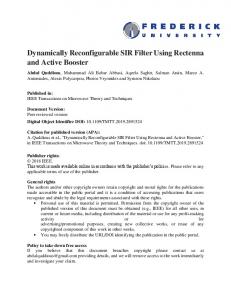
filtering. Speech filters, in particular, have received a lot of attention in the field of human-robot interaction for foveating a robot towards a target [5] in 1D. Valin uses specially designed filters for separating out speech signals from ambient and robot noise [1] to identify the angle (yaw, pitch) to a speech source and do auditory streaming. Also, filters modeling the precedence effect, a biological phenomena that emphasizes early sounds over reverberations, can track timevarying signals such as speech or music [6]. If a source position is necessary, however, and not just its angle, then one robotic solution is to move the physical array and sample in multiple locations. Angular estimates from each sample location, when combined together, triangulate upon one or more targets in 3D. Combining the measurements effectively becomes the difficult part, with both evidence grids [4] and the RANSAC [7] algorithm having been used for this purpose. When the microphone array does not need to remain on the robot, then a good alternative solution in some cases is to mount microphones throughout the environment. Aware environments research has demonstrated this in home environments to keep track of their occupants [8]. Nakadai et al [2] demonstrated this successfully with 2D localization of a speaker in a single room, ultimately integrating both local measurements from an on-robot array with the room mounted array using a particle filter. The auditory streams from the robot measurements, however, were not compared directly to the room mounted microphones due to the lack of precise inter-microphone spacing. In general, however, the room mounted array solution suffers from deployment problems. Relatively rapid re-calibration techniques using high-frequency pulses [10, 11] are effective for localizing disparate microphones, but have reduced accuracy in the presence of obstacles. Furthermore, hardware setup may be prohibitive. Wires need to be strung throughout the room or built into the environment, or wireless systems need to manage batteries, base stations and interference from other wireless type devices. All of which limits deployment of large room mounted arrays to arbitrary environments. III. DYNAMIC MICROPHONE ARRAY DESIGN In contrast to previous work mixing multiple microphone arrays together [2], this work integrates microphones together at the signal level. Combining data at the signal level means that sound localization probabilities are calculated for every microphone pair instead of each separate microphone array. Therefore, each detected microphone in the environment, when combined with on-robot static array, doubles the number of total sound localization estimates. Furthermore, because environmental microphones are generally located further away from the robot, the baseline of the array is extended tremendously, improving overall accuracy. The system we have developed to test our dynamic array is shown in Figure 1. An iRobot B21r is equipped with a
Figure 1. Wireless microphones (right) are rigidly attached to fiducials. The B21r robot uses its onboard camera to localize these microphones and combine their signals with 2 overhead microphones.
single Point Gray firefly camera for localizing fiducials attached to wireless microphones. The SR3000 time of flight camera seen in Figure 1 is not currently used except as a visualization aid. The wireless microphones detected by the robot are continuously streaming to 2 variable frequency base-stations mounted on the robot. The signals of both the 2 wireless base stations and 2 robot-mounted microphones are amplified with battery powered preamps and then sampled using an 8 channel PCMCIA A/D converter. Currently, all microphone streams are continuously sampled by the robot. Stream inclusion in sound localization is then guided by software. In the future, however, we hope to remove this need for a base station per wireless microphone by either synchronizing streams locally and then transmitting via traditional wireless network [10], or dynamically switching between wireless frequencies depending upon the set of visible fiducials. The remainder of this section describes the sensing components of this system in more detail. Specifically, it covers the modifications necessary for accurate visual localization of the microphones, and the algorithms used to localize sound sources from a dynamic microphone array. A. Visual Microphone Localization Dynamic microphone localization is achieved through rigidly affixing fiducials to the wireless microphones. The fiducials we use are developed by the ArToolkit [3] which can recover fiducial positions in real time. When using the ArToolkit in a real time signal processing task, the system must be calibrated and parametrically optimized before accurate position estimates can be recovered. We will review calibration of ArToolkit parameters first, followed by camera calibration techniques and testing results. The ArToolKit provides a system for generating and tracking planar markers. The system is based on the
5637
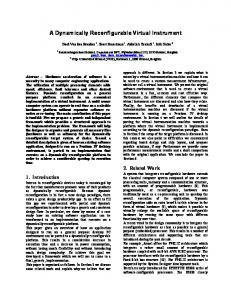
capability of recognizing black squares printed on white backgrounds commonly known as fiducials. To recognize the fiducials, a segmentation algorithm is employed that labels black pixels as part of the square and white pixels as part of the background. For pixels containing only a white background or black square, the labeling is straightforward. Pixels on the border of the square, containing portions of both black and white colors, however, are often highly ambiguous and result in incorrect estimation of a fiducial’s boundary in an image. Two factors that contribute to boundary ambiguity are the use of a Bayer pixel pattern and image blur. The Bayer pixel pattern utilizes an uneven spacing of red, green and blue pixels used in most modern cameras. The process of generating a color image requires demosaicing the pixel pattern to generate a full resolution image. The image interpolation necessary for demosaicing introduces blurring about edges of image features. In addition to blurring caused by the demosaicing process, blurring occurs due to lens/image plane effects. The end results of image blur is the need to parametrically set the image segmentation threshold in the ArToolKit. In work presented here, the threshold boundary was modified until the segmentation boundary for our fiducial coincided with the actual boundary of the fiducial in the image. Without setting the segmentation threshold, the ArToolKit consistently underestimated fiducial size, resulting in underestimated distances between camera and fiducial. Once the segmentation parameters were set, internal calibration of focal length and distortion was performed. To overcome image distortion, the ArToolKit’s distortion calibration tools were used to solve for the center of projection and image distortion characteristics. For recovering the camera’s focal length, we used the fiducials themselves. Fiducials were placed in known locations and then the focal length was modified until the distances between fiducial locations matched the actual theoretical distances between the fiducials. By using the fiducials to solve for the focal length, the internal calibration parameters of the camera were determined while further minimizing any effects of the aforementioned segmentation parameters. Once the camera was calibrated, we tested fiducial localization accuracy by comparing distances between fiducials placed at known locations. Two tests were performed. First, we evaluated inter-fiducial location accuracy in regard to translations away from the camera with error metrics shown in Figure 2. These results show a greater error for greater distances between fiducials. This demonstrates that fiducials further away from the camera, necessary for producing larger inter-fiducial distances, caused the inter-fiducial distance to be under estimated. This deterministic underestimation can be partially attributed to inaccurate focal length calibration. With due diligence, the decrease in fiducial accuracy with respect to range could be mitigated by additional modification to the camera focal length parameters. However, the projected mean error for a
Figure 2. Measurement error vs. inter-fiducial distance for: (Top) translations away from the camera, (Bottom) horizontal translations
2-m inter-microphone distance was still