EFFICIENT ON-LINE COMPUTATION OF CONNECTIVITY: ARCHITECTURE OF THE CONNECTION UNIT OF NESPINN Ulrich Roth, Frank Eckardt, Axel Jahnke, and Heinrich Klar Institut für Mikroelektronik, Technische Universität Berlin Jebensstr.1, Sekr. J13, D - 10623 Berlin E-mail:
[email protected] [email protected] Abstract We present the architecture of a connection unit for NESPINN, the neurocomputer for the simulation of spikeprocessing neural networks. Due to on-line computation of connectivity, this connection unit enables access to connections in forward and backward direction. Access to connections in both directions is necessary for learning. The connection unit offers a performance of up to 100 MCPS or 50 MCUPS with optimized memory size for the weights. This performance is mainly a result of a modular chip architecture, where the operations of the modules are asynchronous on system level and determined by the dataflow. Furthermore, we developed a address scheme for a four times interleaved weight memory, which exploits regularities of the address stream.
1
Introduction
This paper presents a connection unit for NESPINN, the Neurocomputer for the simulation of spiking neurons [1]. The NESPINN-system will enable real-time simulations of large-scale spike-processing neural networks. Spiking neurons are complex integrate-and-fire neurons which may possess the following properties: postsynaptic potentials with realistic time course, absolute and relative refractory periods, axonal delay times and different types of synapses for every neuron [2][3][4][5]. Developing hardware for high-performance neural network systems confronts us with several problems. A first approach would be to integrate a lot of processing circuits that perform neuron calculations and a large capacity onchip memory in which synaptic weights can be stored on one chip. However, there are limits to the number of processing circuits and the amount of memory that can be integrated on a single chip using present VLSI technology. It is until now not possible to implement more than 64 neurons on one chip, even with analog or mixed analog/digital implementations (e.g. pulse stream networks). Thus, for the simulation of large-scale neural networks a
processor-based approach is the first choice. A certain number of parallel processing elements processes partitions of a network. Storing the weights on-chip limits drastically the number of neurons which can be simulated. So, for simulation of large-scale networks synaptic weights has to be stored in large off-chip DRAMS. The I/O-bandwidth becomes now a critical issue, because DRAM access times are typical much larger than system cycle times. A sophisticated organization and addressing scheme is necessary for the weight-memory. For forward fully-connected networks, e.g. MLP, interleaved memory with weights stored in a layer-connection matrix is a usual solution. But for sparsely connected networks, which we will regard, storing in connection lists for each neuron is clearly more efficient. The data items of these lists consist of weight and address of connected neurons. However, almost all learning algorithms require that connections of the network can be accessed in two ways: forward and backward. The Back-Propagation algorithm requires e.g. the transposed weight matrix for the calculations of error values. In our case, on-line Hebbian-learning, it is necessary to access weights forward from sending to receiving neuron and backwards from receiving neuron to sending neuron in order to update weights in dependence of the activity of sending and receiving neuron [13]. Storing the connection information for both ways would require a large-capacity connection memory, because it is necessary to store a pointer to every weight and connected neuron for one direction. In the following we will present a connection unit with a dedicated processor chip for the NESPINN-system, which aims to tackle the mentioned problems. Due to on-line computation of connectivity with a tailored chip architecture, and a sophisticated addressing scheme for a four times interleaved weight memory, this connection unit offers up to 100 MCPS or 50 MCUPS and a drastically reduced weight memory size compared to a memory-only approach. The remainder of the paper will proceed as follows: In section 2 we survey the specific properties of spiking neurons and the important implementation issues regarding
connectivity. Section 3 describes the system architecture of NESPINN in which the connection unit has to fit. Section 4 presents the new connection unit: the supported algorithms, the chip architecture and the results of our performance evaluation.
2 2.1
Spiking neural networks Features
Spiking neurons are complex integrate-and-fire neurons [2][3][4][5]. Regarding connectivity they possess the following properties: • Neurons communicate with each other only via delayed spikes. • Incoming spikes were weighted and induce a postsynaptic potential according to an impulse response function. • Impulse response functions are constructed of one or several leaky integrators. A leaky integrator is described in a discrete version by IP(n+1) = r * IP(n), where IP is an internal potential and r a decay factor. • Internal potentials (IPs) are combined in output functions containing addition, subtraction and/or multiplication and at least a threshold function. • Networks may consist of some 105 neurons and can be divided in layers of neurons with equal properties. Each neuron is connected with up to 104 other neurons. • The connectivity structure of the network can be divided into two groups: 1.) regular connections, which follow some deterministic rules (e.g. convergent, divergent or homogeneous connections) and 2.) non-regular connections (sparse, random connections). • Weights are on-line modified according to local Hebbian-rules. The update of the weights depends on the activity of sending and receiving neuron
2.2
Implementation issues
Implementing spike-processing networks on digital computers the time t proceeds in discrete basic time units T (usually T = 1ms). We will call the simulation of one basic time step for the whole network a time slice (TS). The processing in each time slice involves three operations: input: spikes have to be distributed and the spike-receiving neurons have to increment their corresponding IP. output: each neuron has to combine its internal potentials and to decide whether to emit a spike or not decay: the internal potentials have to be decayed for each neuron. Regarding these operations, we can apply several methods in order to speed-up the simulation: • The network activity (average number of spikes per TS / number of neurons) is usually quite low. A very efficient communication scheme for such networks is the eventlist protocol. Only the addresses of spiking neurons are
registered in a spike event-list [6]. Hence, only the small number of these active neurons have to distribute spikes. • Typically, spike-processing neural networks are not fully connected. One method of representing the connectivity of sparsely connected networks is the use of lists, one for each neuron ni. The items in the lists are data sets consisting of weights, delays and addresses. The addresses aj in the list may denote the neuron nj, to which ni sends a spike or from which ni receives a spike. The former represents sender-oriented, the later receiver-oriented connectivity [8]. For low network activity the senderoriented method is advantageous [9][10]. It permits that only spike-receiving neurons have to compute the input function. However, learning requires that the connectivity from spike-receiving neuron to spike-sending neurons is also known [13]. Concerning the simulation on a parallel computer, the computer architecture has to be well suited for the computation of all three steps. In a simulation study we showed that none of the available neurocomputers is able to reach required performance [11][12]. High performance parallel computers would be suitable [7] but their high acquisition and maintenance costs justify their use only for very few applications. According to our results, we propose the use of a bus oriented parallel computer with dataflow characteristics and neuron-parallel mapping. Neuron-parallel mapping means that all synapses or inputs of a neuron are mapped to the same PE. By this way different neurons are processed in parallel, but the inputs of one neuron are processed serially. This approach achieves a good performance for both the spike propagation and the computing of decay and output function.
3
The NESPINN system
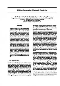
An efficient architectural approach for a digital accelerator for spiking neurons has been developed together with the research group from Hartmann, Paderborn [9]. One result of this approach is the architecture of NESPINN. We included spike-event-addressing, sender-oriented connectivity units, fixed-point arithmetic, neglecting of small IPs, an efficient neuron-parallel mapping scheme and a mixed dataflow/SIMD mode in the architecture of our neurocomputer for spike-processing neural networks. NESPINN will simulate spike-processing neural networks with up to 4 M neurons with up to 104 connections each. The time needed for the simulation of one time step will be in the range form a few µs to ms. Figure 1 shows a block diagram of one NESPINN-board. The system may be build with 16 equally equipped boards. One board consists of spike-event lists (implementing the event-list protocol), two connectivity units (containing the network topology), the neuron state memory (containing Figure 1: Block diagram of NESPINN-board, showing
NESPINN-chip RC Event-lists
PE0
SRAM
PE1
SRAM
PE2
SRAM
PE3
SRAM
WU0 VME Bus
VME CU WU1 NRC
Delay Unit
board and NESPINN-chip architecture the neuron data), and the NESPINN processor chip with four PEs with 2kB local on-chip memory each and two weight units, performing the update of the weights. Features of the architecture which are important for the connection unit are now described.
3.1
Network mapping
The computation of large networks has to be split into several parts due to the limitation of on-chip memory of the NESPINN processor chip. The part of the network computed together at one simulation interval will be called a sector. The numbers of sectors ns and the number of neurons per sector nb depends on both the capacity of the local
0 1 2 3 4 5 6 7
0 1
2 3 4 5 6 7
8
0
1
2
3
0
1
4
5
6
8
7
4
5
9
0 10
11
8
12
13
14
15
0
1
2
4
5
6
8
9
12 0
2
3
0
6
7
4
9
1 10
11
8
12
13
14
15
12
3
0
1
2
3
0
3210
7
4
5
6
4
11
8
9
3310
7 11
8
13
14
15
12
13
14
15
12
1
2
3
0
1
2
3
0
X
on-chip memory and the complexity of the neuron models, i.e. the number of IPs of a neurons. For example: a network of 16 k neurons with 4 IPs will be mapped to ns = 16 sectors with nb = 1 k neurons each. For network-to-sector mapping the layer of a network is divided into rectangular blocks with ns neurons (see fig. 2). Each neuron which has the same position relative to its block is mapped to the same sector. The neuron address consists now of a sector number SN and a block number BN. During the simulation of one sector only the block-number is required to address a neuron. Assuming spatial and temporal correlated activity, the active neurons of one time step are forming local clusters. The neurons of one cluster are now mapped to different sectors. Regarding the whole network, active neurons of one time-step are equally distributed over sectors and processing elements, and a balanced workload is achieved.
3.2
Connection units
2
34
Y BLOCK NUMBER (BN) SECTOR NUMBER (SN) Figure 2: Mapping of a layer in X/Y-representation to SN/BN-representation.
The two connection units, NRC (non regular connections) and RC (regular connections), hold the network topology. The connection units have to compute serially the connections to neurons of the actual sector given by an active neuron number from the spike-event list. The connections consist of the corresponding weight and a pointer *N to the specific input of the receiving neuron. In order to increase the system performance, a senderoriented addressing scheme with connection lists has been implemented for the NRC-unit. The architecture of the NRC-unit has been proposed by Hartmann [9]. It consists mainly of pointer-addressed, interleaved memory (64 MB DRAM) for *Nx, W and pointers. The RC-unit will be described in depth in the next chapter. This connection unit supports hebbian learning. Therefore, it has also to com-
pute connections from active neurons backwards to sending neurons. The target neurons, which are active regarding the learning process, are stored in a second event-list.
3.3
Interface to NESPIN chip
The NESPINN processor chip contains four processing elements (PEs) with local memory and two weight units. It will be implemented in 0.7 µm CMOS technology. and operate at a frequency of 50 MHz. Each clock cycle a maximum of two weights can enter the chip. The interface to the RC-unit is implemented with separate FIFOs for incoming weights and modified outgoing weights. Processing of a sector is divided into three phases: INIT, input&decay and output. During these phases the chip operates in either dataflow or SIMD mode. In the sector initialization phase (INIT), the sector program code for each neuron in the sector are transferred from external neuron state memory. In the input&decay phase, either weighted spikes are received from the connection units or IPs will be loaded from the neuron state memory, and decayed. The instructions performed by a PE in this phase are controlled by the dataflow. In the output phase, output functions will be computed and numbers of active neurons will be transferred to the spike-event lists. The system operates now in SIMD mode. During input&decay phase the two weight units update weights from sending neurons to receiving neurons [13]. During output phase the weight units modify weights from active target neurons in dependence of the activity of the sending neurons. This information is now available from the processing elements.
4
Regular connection unit of NESPINN
Summing up, the regular connection unit has the following tasks: input phase: propagating weights from source neurons to target neurons. output phase: back-propagating weights from target neurons to source neurons. In both phases the connection unit has furthermore to write back weights which have been modified by Hebbian-learning. Incorporating the backward path into a sender-oriented addressing scheme, which relies only on pointer accessed memory, faces severe problems. Our NRC-unit e.g. stores for each source neuron a pointer to a connection list in weight memory and this list of weights (9 bit) and pointers *N (12 bit). Regarding a weight memory of 64 M weights, the backward projection would require an additional connection memory (same address space) consisting of lists for each target neuron. The list items would be pointers to source neurons (12 bit) and addresses of the corresponding
weights (26 bits). In order to avoid this huge storage effort, we suggest online computation of connectivity. Only the weights are stored in a DRAM, while pointers to source or target neurons and weight addresses are computed whenever they are required during run-time. This computation is done according to connection rules in dependence of the neurons spatial position. Different connection schemes between two layers are implemented by a specific parameter set for a connection rule. In the following paragraphs we will survey the algorithms, which our connection unit will support and their mapping to a ASIC. Computation of connectivity compromises mainly two tasks: 1. computation of connected neurons according to a specific rule (see 4.1) and 2.generation of weight addresses (see 4.3).
4.1
Computation of connectivity
The computation of connected neurons involves mainly the following operations: data decode, field computation, sector match, and block count. Data decode maps incoming neurons in SN/BN-representation to X/Y-representation according to equation 4.1 and equation 4.2, where X/Y denotes the X/Y-coordinate, BN the block number, SN the sector number, BCx the number of blocks in x-direction, and SCx/y the number of sectors in x- resp. y-direction. X = ((BN mod BCx) * SCx) + (SN mod SCx) Y = ((BN int BCx) * SCy) + (SN int BCx)
(4.1) (4.2)
Field computation yields the number of the first and the last connected neuron in x- and y-direction. Both direction are independent of each other, so, we will describe only the one-dimensional case. The computation distinguishes between divergent, few-to-many connection (F2M,see fig. 3) and convergent, many-to-few connections (M2F, see fig. 4). 12 13 14 15 16 17 18 19 20 2122 232425 26 2728 29 30 31 32 33 34 35
4
5
6
7
Figure 3: Few-to-many connection (dashed: connections due to scale, solid: connection due to overlap) firstx = X ⋅ scale x – overlap x – offset x
(4.3)
last x = X ⋅ scale x + ( overlap x + offset x + scale x – 1 )
(4.4)
The computation of the first and the last neuron is done
2
3
4
0
1
5
2 4 5 6 7 8 9 10 11 12 13141516 17 18 1920 21 22 232425 26 27
3
Figure 4: Many-to-few connection (dashed: connections due to scale, solid: connection due to overlap)
first x = last x =
X – overlap x + offset x --------------------------------------------------------------------------scale x X + overlap x – offset x ---------------------------------------------------------------------------scale x
0
1
2
3
SN
BN
SN (bin)
00000000 00000001 00000010 00000011 00000100 00000101 00000110 00000111 00001000 00001001 00001010 00001011 00001100 00001101 00001110 00001111
0 1 2 3 0 1 2 3 0 1 2 3 0 1 2 3
NEURON (bin)
(4.5)
Figure 5: Sector match, left solid circle represents incoming neuron and right solid circles connected neurons for sector SN = 1
(4.6)
4.2
One-to-one and fully-connected layers are special cases of both connection schemes. A backward-projection can easily be done, because a M2F-connection in forward direction corresponds in backward direction to a F2M-connection, and vice versa. Sector match, the next operation, matches the computed field to the actual sector. By this way, we get the number of neurons which are connected with neurons of the actual sector and the corresponding first and last block number in x- and y-direction (see fig. 5). During sector match we can perform the required border checking. Block count, finally, increases the first block numbers until all block numbers are delivered. This operation involves a concatenation of the x- and y-part of block numbers (BNx resp. BNy) to a linear block number BN according to equation 4.7, where BCx denotes the number of blocks in x-direction. BN = BN x + BN y ⋅ BC x
0 1 2 3 4 5 6 7 8 9 10 11 12 13 14 15
BN (bin)
NEURON
according to equation 4.3 and equation 4.4 for few-tomany connections resp. equation 4.5 and equation 4.6 for many-to-few connections. It requires only three parameters for each direction: scale: representing size relation between connected layers, F2M: target layer size / source layer size M2F: source layer size / target layer size overlap: denoting the number of additional connected neurons in target field (F2M) resp. source field (M2F) offset: special parameter to shift the target rep. source field.
(4.7)
The neurons resp. IPs in the local memory of the NESPINN processor chip are only addressed by block numbers. The sector number part is constant during the simulation of a sector.
Weight memory organization
As mentioned before, a maximum number of two weights may enter the NESPINN processor chip per system cycle (ft = 50 MHz). In contrary, DRAM access times are much larger, typically 110 ns for single access and 40 ns in page mode. So, we need a interleaved weight memory organization and addressing scheme, which exploits regularities of the address stream. The usual addressing of weights with coordinates of source and target neurons is not a feasible scheme in our case. This scheme would lead to wasted address space, because fully-connected layers are not the normal case. When we store for each neuron its connection matrix in a linear list, it is possible to store all weights of connections between two layers in dedicated sections of the weight memory without wasting of address space. The address of a weight consists now of a start address to this section and a neuron number and weight number as offset. The weight number WN denotes in a linear way the position of a weight resp. connected neuron in the connection matrix of a neuron. Regarding access times of DRAMs we would like to access all weights in page mode or interleaved single access mode. Interleaved access without wait states would require 2 memory banks for page mode or 8 banks for single access. However, our address stream is unfortunately
not highly regular, because connections are computed event-controlled and connection parameters (e.g. layer size, overlap etc.) can be freely configured. So, it is not possible to organize the memory in such a way, that we can always guarantee access without wait states in both directions. The memory organization, which we developed, tries to enable access in page mode in one direction and interleaved single access in the other direction. Our weight memory consists of four banks of 16 MB. Accepting one wait state after four single accesses we can cut in half the control effort compared to a memory with 8 banks. Each bank is build of 4 M x 32 b, where one word holds four weights.
4.3
Address generation
In order to exploit regularities in the address stream we build a address different for F2M- and M2F-connections. Figure 6 shows generation of the logical address out of sector, block and weight number and the mapping to the physical address *W. The arrows indicate variable bit size of the logical parts. Logical address of a F2M-connection SNt
SNs
BNs
WNs
Logical address of a M2F-connection SNs
SNt
BNt
WNt
Physical address of weight memory row address
column address
B
W
Figure 6: Generation of logical address and mapping to physical address *W, with 11 bit row address, 11 bit column address, 2 bit bank select B, and 2 bit word select W. (The subscripts s and t denote source resp. target) Computation of weight numbers for a F2M-connection in forward direction is done according to equation 4.8, for a M2F-connection according to equation 4.9. The subscripts in denotes the incoming neuron, and con the connected neuron. In backward direction, we have to change for a F2M-connection to the equation for a M2F-connection, and vice versa. When the connection scheme in y-direction differs from the scheme in x-direction, we have to use equation 4.10 for a M2F-connection in y-direction and a F2M-connection in x-direction, equation 4.11 is used for a F2M-connection in y-direction and a M2F-connection in x-direction. Otherwise the weight number in y-direction is computed in analogy to equation 4.8 and equation 4.9. Finally, we form a
linear weight number out of the x- and y-part according to equation 4.12, where WCx denotes the number of weights in x-direction. WN x = Xcon – ( X in ⋅ scale x – ( overlap x – offset x ) )
(4.8)
WN x = Xin – ( X con ⋅ scale x – ( overlap x – offset x ) )
(4.9)
WN y
=
X in – overlap y + offset y X con – --------------------------------------------------------------------------------scale y
(4.10)
WN y
=
X con – overlap y + offset y X in – -------------------------------------------------------------------------------------scale y
(4.11)
WN = WN x + WN y ⋅ WC x
(4.12)
Regarding for example a F2M-connection: in forward direction target sector, source sector and block number will remain constant for a incoming neuron. Only the weight number will increase linear. This enables access in page mode to the four memory banks. In backward direction the target sector and the source sector number will remain constant for a incoming neuron. The block numbers of the connected neurons will increase linear. This enables interleaved single access or even access in page mode, when the bit size of block and weight number is smaller than the size of a column address (15 bit). Our addressing scheme exploits furthermore that active neurons are ordered by first increasing block numbers and than increasing sector numbers due to the incremental sector processing of the NESPINN-chip.
4.4
Chip architecture
The chip architecture of our processor chip is displayed in Figure 7. The described operations are handled by dedicated modules, operating in a feed-forward pipelined fashion. Each module consists of a datapath, control circuitry and a local on-chip memory for parameter sets of connections. Incoming neuron numbers enter the chip together with a connection number CN. The connection number serves as an address to the actual parameter sets. A maximum number of 32 parameter sets are loaded during a initialization phase at the beginning of the simulation of one sector. During address computation the modules operate asynchronous i.e independent of each other, synchronized by two handshake signals. Performed operations are determined by the dataflow. Only start and end of a sector simulation phase is controlled by a central sequencer.
BLOCK NUMBER INPUT NEURON
DATADEC.
CON. NUM.
FIELDCOMP
BLOCKCOUNT
LOGICAL-
PHYSICAL-
ADDRESS
ADDRESS
SEC. MATCH
DRAM CONTROL WEIGHTADDRESS
INPUT NEURON CONTROL-PATH DECODE-
FIELD-
MEM
MEM
LOGICALADRESSMEM
PHYSICALADDRESSMEM
NEURON-PATH ADDRESS-PATH CON.-PARAMETER
Figure 7: Block diagram of the connection processor chip Data decode, field computation and sector match compute first the x-information and than the y-information of connected neurons for a incoming neuron. This serial processing reduces chip area and leads only for neurons with less than two connections to performance degradation. Restricting layer size to 2n, with a arbitrary natural number n, allows to change all division operations to shift operations. Block count increases block numbers of connected neurons by two, when possible. This enables to address simultaneously two connected neurons. Logical address computes weight numbers, and physical address forms a weight address by adding the start address of a connection scheme and concatenation of the different parts of the address. The DRAM-controller monitors finally the state of the weight memory. When possible, it emits every cycle weight address and number of connected neuron for two successive connections. The DRAM-controller handles both reading of connections, which are stored in a FIFO for the NESPINN-chip, and writing back of modified weights, which are stored in a FIFO by the NESPINN-chip. The design of the connection processor was done in a VHDL-based design-flow with macro cells for datapath circuits and memory. Control circuitry was synthesized to standard-cells. For test purpose we added scan-path and direct access to on-chip memory. The chip will be fabricated with a die size of 52 mm2 in ES2-0.7 CMOS-technology and operate with a clock frequency of 50 MHz. At the time of writing this paper we are finishing the layout.
4.5
Estimated performance
With VHDL-simulations of our connection processor
after layout we estimated the performance of our connection unit. We simulated layers with different F2M-connections, different M2F-connections, and mixtures of both connection schemes with and without learning. The measured performance was in the range from 24 to 100 MCPS or from 17 to 50 MCUPS. According to our expectations, we achieved the best results for F2M-connections in forward direction and M2F-connections in backward direction. One-to-one-connections displayed the lowest performance. Performance beneath the peak performance is due to the following reasons: - only one weight can be addressed with one access instead of two weights - a sequence of neurons with less than two connections enters the chip every second cycle - wait states are encountered when between two accesses to one memory bank less than four accesses to different memory banks are performed in single access mode, or less than one access in page mode. The effects of performance degradation are reduced on system level due to the FIFO-interface and the dataflow-processing of the NESPINN-chip. Only the weight units are idle during cycles in which no connection may enter the NESPINN-chip.
5 Conclusion We presented a connection unit with a dedicated processor chip for the NESPINN-system. This connection unit enables access to connections in forward and backward direction, due to on-line computation of connectivity. Access to connections in both directions is necessary for learning. The connection unit offers a performance of up to
100 MCPS or 50 MCUPS with optimized memory size for weights. This performance is mainly a result of a modular chip architecture, where the operations of the modules are asynchronous on system level and determined by the dataflow. Furthermore we optimized memory access times by a addressing scheme for a four times interleaved weight memory, which exploits regularities of the address stream. Compared to a only memory-based approach this connection unit offers a drastically reduced weight memory size. But our connection unit is restricted to regular connection schemes ranging from one-to-one to fully connected layers. Irregular connections (e.g. random connections) have to be mapped to regular connections with wasted address space. An implementation of address computation with a available standard-processor or DSP would not be feasible, according to our examinations. Just the computation of a connected field would require more than 16 lines of assembler code. A single-processor solution would not achieve the required performance. Our approach is not limited to spike-processing networks. On-line computation of connectivity is advantageous, whenever the majority of connections of a network are local field connections and fully connected layers are not the normal case. Acknowledgments In appreciation of their help during the development of the connection unit, we would like to thank Nasser Mehrtash, Maher Taibi, Panagiotis Vlassakidis and Hai Wang. Furthermore we would like to thank G. Hartmann and G. Frank for stimulating discussions. This work has been supported in part by the DFG under Grant No. Kl 918/1-3 and the BMBF under Grant No. 01 M 3013 A 8. References [1] A. Jahnke, U. Roth, H. Klar: "A SIMD/Dataflow Architecture for a Neurocomputer for Spike-Processing Neural Networks (NESPINN)", MicroNeuro'96, 232-237, 1996. [2] R. Eckhorn, H. J. Reitboeck, M. Arndt, P. Dicke, "Feature linking via stimulus-evoked oscillations: Experimental results from cat visual cortex and functional implication from a network model", Proc. ICNN I: 723-730, 1989. [3] W. Gerstner, R. Ritz, J. L. van Hemmen, "A biologically motivated and analytically soluble model of collective oscillations in the cortex", Biol. Cybern. 68: 363-374, 1993. [4] G. Hartmann, "Hierarchical neural representations by synchronized activity: a concept for visual pattern recognition", In: Neural Network Dynamics, edited by J. G. Taylor et al., Springer Verlag, Berlin, pp. 356-370, 1992. [5] W. Maas,"Lower Bounds for the Computational Power of Networks of Spiking Neurons", Neural Computation 8, 1-40, 1996. [6] L. Watts, "Event-Driven Simulation of Networks of Spiking
Neurons", Advances in Neural Information Processing Systems 6: 927-934, 1994. [7] E. Niebur, D. Brettle, "Efficient Simulation of Biological Neural Networks on Massively Parallel Supercomputers with Hypercube Architecture", Advances in Neural Information Processing Systems 6: 904-910, 1994. [8] J. Lazarro, J. Wawrzynek, "Silicon Auditory Processors as Computer Peripherals", Advances in Neural Information Processing Systems 5: 820-827, 1993. [9] G. Frank, G. Hartmann, "An artificial Neural Network Accelerator for Puls-coded Model-neurons“, ICNN’95, 1995. [10] U. Roth, A. Jahnke, H. Klar, "Hardware Requirements for Spike-Processing Neural Networks", in: From Natural to Artificial Neural Computation (IWANN´95), edited by J. Mira and F. Sandoval, Springer Verlag, Berlin, pp. 720-727, 1995. [11] A. Jahnke, U. Roth, H. Klar, "Towards Efficient Hardware for Spike-Processing Neural Networks",. World Congress on Neural Networks, 460-463, 1995. [12] A .Jahnke, T. Schoenauer, U. Roth, K. Mohraz,H. Klar, "Simulation of Spiking Neural Networks on Different Hardware Platforms", ICANN‘97. [13] U. Roth, A. Jahnke, H. Klar, "On-Line Hebbian Learning for Spiking Neurons: Architecture of the Weight-Unit of NESPINN",ICANN’97.