Fuzzy logic based mobile robot target tracking in dynamic hostile environment Tharindu Fernando
Harshala Gammulle
Department of Statistics and Computer Science Faculty of Science, University Of Peradeniya, Peradeniya, Sri Lanka.
[email protected]
Department of Statistics and Computer Science Faculty of Science, University Of Peradeniya, Peradeniya, Sri Lanka.
[email protected]
Chamila Walgampaya Department of Engineering Mathematics Faculty of Engineering, University Of Peradeniya, Peradeniya, Sri Lanka.
[email protected]
Abstract— With the increasing number of applications, mobile robots are required to work under challenging conditions where the environment is cluttered with moving obstacles and hostile regions. In this paper we propose a fuzzy logic based control system for mobile robot target tracking and obstacle avoidance in a dynamic hostile environment. Given the existing body of research results in the field of obstacle avoidance and path planning, which is reviewed in this context, particular attention is paid to integrate computer vision based sensing mechanisms to robust fuzzy logic based navigation control method. Depth and colour information for both navigation and target tracking are to be captured using a Asus Xtion PRO sensor, which provides RGB colour and 3D depth imaging data. The fuzzy logic based navigation control algorithm is implemented to control obstacle avoidance, hostile region avoidance and target tracking. The effectiveness of the proposed approach was verified through several experiments, which demonstrates the feasibility of a fuzzy target tracker as well as the extensible obstacle and hostile region avoidance system. Keywords— fuzzy logic control, mobile robot target tracking, obstacle avoidance.
I.
INTRODUCTION
In recent years, there has been a growing realization that mobile robots are one of the key factors affecting the success in the service sector. Mobile robots are becoming popular and used extensively in many fields, such as military and nuclear power plants as a method of intervention in hostile environments or in warehouse as a method of transport and inventory inspection. Generally in computer integrated manufacturing (CIM) systems automatic guided vehicles (AVG) are replaced with mobile robots, as they employee intelligent behaviour to cope with the open real world environments without the constraints that are imposed in AVGs [3]. Mobile robots posses the
978-1-4799-6092-7/15/$31.00 ©2015 IEEE
capability to interact with humans and other robots in the environment and navigate itself to the desired target without imposing additional constraints on the working environment. In dynamic challenging environment finding hostile conditions such as a collapsing building or an opponent may become a possibility. But traditional industrial robots assume that the state of the world is known with near certainty. Therefore there is a need for a robust, intelligent system which can navigate mobile robots dynamically and capable of graceful motion with increased dynamic stability. Furthermore, hostile region avoidance capability of mobile robots is well tested in covert robotics [2]. It is a relatively new field in which covert navigation abilities are developed for robots to carry out different missions. The robot derives various strategies based on the environment and the hostile observers' locations. Based on those strategies a motion plan is generated which minimizes the risk of being detected. In many research findings fuzzy logic techniques are tested for the navigation of mobile robots. A fuzzy control module for mobile robot target tracking is proposed in [4]. The authors have only tested the approach for motion control but not for obstacle avoidance. Another fuzzy logic based target tracking system for mobile robot is presented in [7]. The system is comprised of infrared (IR) sensors to detect obstacles and two wheeled robots, the first one as the moving target and the second as the tracker. Apart from IR sensors, Ultra sonic sensors and laser range finders are the most commonly used sensors in depth sensing mechanisms [5]. Deviated from that several studies have being conducted using camera information to navigate the robot in a dynamic environment. With the introduction of low cost 3D cameras, several independent studies have emerged in order to exploit the
advantages of this equipment in other applications, ranging from healthcare to robotics. Due to the use of infrared, the sensor is able to create the depth map even at environments with total absence of light. In [1] the system proposed by Santos et al. an artificial neural network (ANN) is used to recognize different configurations of the environment, for example, path ahead, left path, right path and intersections. The ANN was trained using data captured by the Kinect sensor in indoor environments. The authors proposed the system for surveillance robots as the system was capable to work even under the dark lighting conditions with the use of IR depth sensor in the Kinect sensor. The method lacks in generalisation to different dynamic environments as the ANN should be explicitly trained to track targets and avoid hostile regions. Kloss et. al have proposed a method for adaptive colour processing in object recognition problems with the aid of trained neural network [10]. The method has been tested for mobile robots target tracking problem in the study conducted by Benavidez et. al [11]. The study uses Microsoft Xbox Kinect sensor as the sensing mechanism, which provides RGB colour and 3D depth imaging data. The authors have used this compact sensor for both obstacle avoidance and target tracking tasks. The proposed methods in [18] and [19] which uses a similar RGB-Depth camera set up lack in its applicability to unstructured environments. Both systems have the capability to localize the robot in the environment given a probabilistic occupancy grid of the area for the robot to explore. Hence, a predefined goal is represented in (x,y) coordinate pair. These approaches are ideal for robot application in office environments but hardly applicable for rescue robots and covert robots. II.
MATERIALS AND METHODS
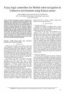
A. Asus Xtion PRO sensor The sensor is capable to capture separate colour and depth information. It uses a RGB camera, a monochrome camera and reflective infra-red (IR) camera for sensing. The sensor generates a depth map in real time, where each pixel corresponds to an estimate of the distance between the Xtion sensor and the closest object in the scene at that pixel’s location. It is expressed as point cloud data in a coordinate system fixed to the monochrome camera. The sensor can capture depth images in 320x240 resolution at a rate of 30 fps [8]. The depth map is a 320 x 240 matrix with 11-bit values, ranging from 0 to 2047, for each pixel. The depth values produced by the sensor will be inversely proportional to the depth. Higher the depth value in a particular pixel, the 11-bit value will be lower. A 3D depth image taken with the Xtion PRO sensor is shown below in Figure 1. For manipulation purposes the depth map is converted to 8-bit gray scale image.
Figure 1 (a): RGB image
Figure 1 (b): Depth image
B. OpenNI SDK OpenNI [6] is a free and open source driver that enables accessing the depth and colour matrices of Asus Xtion PRO using C++ platform. The depth map produced from the IR camera and the texture map produced by RGB colour map of the scene is obtained via OpenNI driver. The maximum depth for automatic object recognition through OpenNI is limited to 4m [9]. C. Modelling Dynamic hostile Environment The modelled environment is dynamic and hostile. There can be any number of static and dynamic obstacles in the region which can enter and exit the scene in any time. When localising the desired target region and hostile regions RGB camera of Asus Xtion PRO sensor is used. The target area is indicated using a red colour laser dot. In order to eliminate the noise from other similar coloured objects in the environment, the gain of the RGB camera is decreased. A colour stream with higher energy is emitted by a laser. Therefore the laser dot will still be visible in the detected frames. This will ensure that the detected colour patches are only from the laser dots. This approach was experimented with shifts in light intensity and was able to obtain acceptable results. The hostile regions are indicated using blue colour laser beams and the existence of multiple hostile regions is possible. The target for the robot is provided using a red colour laser beam and if no such target is provided the robot enters the wondering mode and will start exploring the environment. D. Fuzzy logic control Figure 2 illustrates the composition of the fuzzy logic based navigation control system. Target Tracking Module (TTM), Obstacle Avoidance Module (OAM) and Hostile Regions Avoidance Module (HRAM) are combined to move the mobile robot to the target along a collision and hostile regions free path. The output of the TTM produces a fuzzy set representing the desired turning direction while the outputs from OAM and HRAM produces fuzzy sets representing the allowed turning directions. Target Tracking Module (TTM) RGB map Hostile Regions Avoidance Module (HRAM)
sensor
Depth map
Defuzzification
Moving Direction
Obstacle Avoidance Module (OAM)
Figure 2: fuzzy logic based navigation controller Each control module consists of a set of fuzzy control rules and a fuzzy inference module. Instead of producing an exact value, each control module used produces a fuzzy set. They provide the preferred behaviour of each module. Preferences contain more information, as they give a measure of desirability for each possible command. The control rules could be induced by empirical knowledge. Rule base is composed of many fuzzy implication relations, which are obtained based on lots of experiments, observation and operation experience. Furthermore the actual number of fuzzy rules should be taken depends on many factors. The general principle is on the completeness of the premise. In order to simplify the design process and to enhance the performance factor of the fuzzy logic system, a smaller number of rules were used.
We then use the summation fuzzy operator to combine the preferences of different behaviours intoo a collective preference [17]. After combining individuual preferences through a command fusion module, the collective preference is defuzzified to produce an exactt output value. The structure of each module is further elaborated in below subsections. 1) Target Tracking Module (TTM) m robot is As shown in Figure 3 the target to the mobile indicated using a red laser beam. The anglee α between the red laser beam and the mobile robot is fuzzified f as the desired turning direction.
variables used for angle input are L: Left, FL: Forward Left, F: Forward, FR: Forward Rightt, R: Right. The linguistic variables for the distance variabble which is illustrated in figure 6 are N: Near, M: Medium, F: Far.
Figure 5: Membership function for angle
Figure 6: Membership function for distance
L angle = {L, FL,, F, FR, R} L distance= {N, M, M F}
Figure 3: Target direction Hue, Saturation and Value (HSV) colour spaace separates the intensity information from colour informatioon. Therefore it is the most appropriate colour space for coloour based image segmentation where there can be fluctuationn in illumination conditions. After the conversion of the RG GB colour map produced by the colour camera of the Xtionn PRO sensor to HSV stream, it is threshold for red colour too obtain the red colour area in the image. This produces a binnary image with intensity value equal to 1 for red colour region r and zero otherwise. Post processing morphological operations such as filling holes, is implemented using openCV [122] library. This removes small areas with intensity value equal to zero within a connected component with intensityy value equal to 1. Obtained centroids are superimposed with thhe depth map to measure the distance to the target from the current c location. In the case of existence of multiple targets, thhe closest target is selected. The image plane is partitioned innto five vertical non overlapping columns, labelled as left (L L), forward left (FL), forward (FW), forward right (FR) and right (R) regions. The position of the centroid of the closes target in those partitions is used to evaluate the target direction. The reference model used for the selectioon of the target direction is shown in figure 4. It is selected with respect to o the reference the robot where the robot is in the center of frame.
2) Obstacle Avoidance Modulle (OAM) In this study we have used the method proposed in [13]. The gray level image construucted by depth map is segmented into left, forward left ft, right, forward right and middle regions. Each partition is i analysed for traversable areas by thresholding for lager depth values (i.e. smaller matrix values). This segmentatioon process produces binary images for each partition, with 1 assigned to areas with larger depth than the threshold values v and 0 otherwise. If these resultant areas to be travversed by the robot, they should be large enough to accom mmodate the robot as well. Connected component analysiss [16] is used for this verification. For each connected component c with value 1 in the binary images, width and height are computed and checked against the minimum wiidth and height required to accommodate the robot. As illusttrated in Figure 7, OAM is implemented with eight mem mbership functions. The linguistic variables are L: Left, FL: F Forward Left, AL: All Left, F: Forward, FR: Forward Right, AR: All Right, R: Right, A: All area (No obstacles)..
Forward Forward Right
Forward Left
Figure 7: Membership functiion for allowed direction Right
Left
Figure 4: Reference frame.
TTM is implemented with five membershipp functions for angle input as illustrated in Figure 5.. The linguistic
L allowed_dir = {L, FL, AL L, F, FR, AR, A} 3) Hostile Regions Avoidancee Module (HRAM) When considering the industrial applications, sometimes it might be harmful for the robot to enter hostile areas such as wet areas or areas with high temperature. t Such hostile regions are represented using bluue laser beams and similar
to processing the red colour beams RGB colour map is converted to HSV and then it is threshold to blue colour. After the de-noising procedure the binary im mage is inversed to get the friendly directions. Similar OA AM module, the friendly directions are represented using eigght membership functions. It’s further illustrated by Figure 8. 8 The linguistic variables are L: Left, FL: Forward Left, AL: A All Left, F: Forward, FR: Forward Right, AR: All Righht, R: Right, A: All area
A. First Stage: Rough Global Tuuning. The objective of this stage is to accomplish the main goals of the algorithm such as target tracking, hostile regions and collusion avoiidance. In this stage we generally altered the fuzzy rule base to achieve our main objectives. B. Second Stage: Refined Local Tuning. From the previous contribbution, this second stage polishes the solutions byy means of small local modifications of the rule basee. The optimal path for that particular configuration of thhe environment was taken as the reference and the ruless were fine tuned to get the path of the robot close as muuch possible to the optimal path. III.
Figure 8: Membership function for frieendly direction R, A} L friendly_dir = {L, FL, AL, F, FR, AR 4) Deffuzzyfication Process The fuzzy sets defined in the above steps are defuzzified r the and converted to a final exact output value representing moving direction of the robot using Centre C of Area defuzzification technique. The outputt variable is represented with five membership functionss (Figure 9) for moving direction. The linguistic variables are a L: Left, FL: Forward Left, F: Forward, FR: Forward Righht, R: Right.
RESULTS AND D DISCUSSION
A C++ serial communication library l is implemented to communicate with the Arduino microcontroller m [14] which controls the L298N dual H bridgge motor driver. RP5 robot platform [15] is used with two servo motors. The output variable, moving direction willl indicate what functions should be invoked among the set of functions that resides in the microcontroller. The functiion calls are transmitted serially between host computer annd microcontroller. Several experiments are designeed to test the accuracy of each module separately and the combined operation of the robot. A. Statics obstacles without a traaget The mobile robot navigates throuugh four static obstacles in the environment without a speciffied target (Figure 10 (a)). These obstacles have different shapes s and sizes, two are rectangular and others are cylinddrical shape. The produced path map is superimposed withh the surrounding and the accuracy of the obstacle avoidingg module is measured. The output is illustrated in Figure 10 (b). (
Figure 9: Membership function for moviing direction L moving_direction = {L, FL, F, FR, R} 5) Two-stage Tuning The performance of an FLC depends on its Rule Base and on the membership functions associated to the fuzzy partitions. Hence, it is very important to t adjust these parameters to the process to be modelled. Tuning T methods fit the membership function shapes of the t fuzzy rules obtaining high-performance membership functions. We decided to manually tune our fuzzy controlller by adjusting some rules consequences of the rule base. The tuning was done in two stages.
Figure 10 (a): Environment with static obstacles
Figgure 10 (b): Path taken by the robot
B. Dynamic and static obstacles with a specified target In this experiment one rectangulaar static obstacle is replaced with a dynamic obstacle and a tarrget is specified. As shown on Figure 11 (a) the laser dot is placed 230cm away from the robot. In the first few iteratiions robots sensor doesn’t pick the target. After reachingg 110cm to the target, it recognises the target and switchhes to the target tracking mode. The path taken by the robbot is shown in the Figure 11 (b).
Dynamic obstacle
Initial position
Target Figure 11 (a): Dynamic environment with a specified target
Figure 11 (b): Path taken by the robot
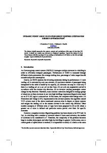
C. Hostile enviroment with a specified target One hostile region is added to the previous setup in (a) (Figure 12 (a)). As the robot prioritises the hostile region avoidance than target tracking, the deviation of path is clearly visible. Figure 12 (b) elaborates these deviations. The path taken by the robot in the previous experiment is shown in doted lines. As the robot enters the hostile area, it prioritizes hostile region avoidance over target tracking. But later there is no significant deference in the two paths. Target
Hostile Region Figure 12 (a): Hostile Figure 12 (b): Path taken by environment with one the robot target D. Hostile enviroment with two targets For the same environment described in (c), another target is added (Figure 13 (a)). The first target is kept 134cm from the initial position and the next in 164cm. After reaching the first target the robot moves to its next goal. Figure 13 (a) illustrates the robots path. The target tracking module selects the closest target in the existence of multiple target. Therefore though the robot sees both targets, it only selects the closest target first. After completely visiting the target 1 it moves towards the target 2. Target 2 Target 1 134cm
164cm
Hostile Region
Figure 13 (b): Path taken by Figure 13 (a): Hostile environment with two the robot targets Due to the nature of the problem, it is hard to objectively evaluate the performance of the proposed methods. To say where the clear movable path is a matter of definition and will probably vary depending on the observer. Taking all this into account we define a measurement called Movement Error (ME) for the goal of quantifying the accuracy of our algorithm.
Movement error (ME) is the average Euclidian distance from the sample points of the optimal path to the path followed by the robot, irrespective of whether the points are above or below the optimal path. ∑ x, x, y, y, ME number of sample points n Where x , , x , are the locations of the ith sample point in the optimal path (op) and robot path (rp) in x Cartesian axis and y , , y , in y Cartesian axis. The optimal path is obtained by manual plotting of the path on top of a Cartesian grid by the human observer. To eliminate the human error in this process we have used 3 observers and the average path for each experiment plotted by these 3 individuals is taken as the optimal path. In order to obtain the path followed by the robot we have stacked the turning directions as well as the distances travelled and plotted the final path on top of a Cartesian grid using a custom written graphics application. The movement error and time taken for robot to complete each experiment is illustrated in the following table. TABLE I.
Experiment
MOVEMENT ERROR AND TIMES PER RUN
A
Movement Error (cm) 3.9
Time per run (s) 12.5
B
2.7
15.1
C
7.8
13.7
D
5.0
17.2
Average
4.8
14.6
We conducted an additional experiment to compare proposed system’s ability against the method proposed in [20]. According to Peasley et. al their proposed method is capable to avoid obstacles at a high rate of speed. But the approach is limited for navigations in a fixed rectangular region. We tested our approach under similar conditions, at translation velocity from 0.2 m/s to 0.8 m/s and rotation velocities from 2.8 rad/s to 5.6 rad/s. The robot successfully avoided all obstacles which were avoided as they had been at slower speeds. This verifies the applicability of the proposed method for all unstructured environments without any additional constraint. Furthermore its none dependency on prior knowledge of the environment, in contrast to methods in [18] and [19], ensures the applicability of the proposed method in exploration applications such as rescue operations. IV.
CONCLUSION
This paper addresses the navigational challenges that arise in settings where mobile robots move in an unstructured environment. We have proposed a robust fuzzy logic based navigation control algorithm and a novel framework for the integration of computer vision based sensing mechanism for mobile robots. The proposed work intends to introduce robots into open, real world environments and navigate them intelligently with minimal human intervention. The
study has addressed the two main issues in robot path planning. Reliable reactive obstacle and hostile region avoidance to guarantee safe operation, and smooth path planning that allows to dynamically adapt environment information to the motion of surrounding persons and objects. The experiments were performed with a mobile robot. A researcher has been used as a dynamic obstacle and special care was taken to model the environment so as to be as close to real world. The experimental results have shown that the proposed architecture provides an efficient and flexible solution to avoid obstacles and hostile regions when navigating the robot in structured and unstructured environments. Furthermore results suggest that low-cost 3D camera can be used to replace higher cost imaging systems in mobile robots. For the future work, we will be extending the fuzzy algorithm to a neuro-fuzzy control system where higher degree of flexibility in automatic object recognition is possible.
[12] www.opencv.org; April 2014 [13] Ravari A.R.N., Taghirad H.D. “ Vision-based fuzzy navigation of mobile robots in grassland environments”, IEEE/ASME International Conference on Advanced Intelligent Mechatronics, 2009, pp. 1441-1446. [14] http://arduino.cc/en/Main/arduinoBoardUno ;April 2014 [15] http://www.pololu.com/product/1060 ;April 2014 [16] Rosenfeld A., Kak A. C. “ Digital Picture Processing”, vol. 1. Academic Press, Orlando, USA, 1982 . [17] Saffiotti .A. “Fuzzy Logic in Autonomous Robotics: behaviour coordination”, IEEE conference in fuzzy systems. July 1997. [18] Bajones M., Einramhof P., Wolf D. “RGB-D sensor setup for multiple tasks of home robots and experimental results”, Intelligent Robots and Systems. 2014 [19]
REFERENCES [1]
Santos D., Correa O., Fernando D. “ Mobile Robots Navigation in Indoor Environments Using Kinect Sensor”, Second Brazilian Conference on Critical Embedded Systems (CBSEC), 2012.
[2]
Marzouqi S., Jarvis R. “Hiding strategies for a mobile robot in hostile obstacle strewn environments”, Cambridge University Press 2014
[3]
Ronald C. ,Robin R. “Autonomous navigation in manufacturing environment”, IEEE Transactions in robotics and automation: 4 August 1990
[4]
Rashid R., Elamvazuthi I. “Differential Drive Wheeled Mobile Robot (WMR) Control Using Fuzzy Logic Techniques”, AMS Proc. of the 2010 Fourth Asia International Conference on Mathematical/Analytical Modelling and Computer Simulation 2010.
[5]
Mohammed F, Ramdane H. “Fuzzy Logic Navigation and Obstacle Avoidance by a Mobile Robot in an Unknown Dynamic Environment”.
[6]
Rusu C. G., Birou I. T. “Obstacle Avoidance Fuzzy System for Mobile Robot with IR Sensors”, 10th International Conference on development and application systems, Suceava, Romania, May 2729, 2010
[7]
Li T. H. S, Chang S. J. “ Fuzzy target tracking control of autonomous robots by using infrared sensors”, IEEE on Fuzzy Systems, vol.12, no.4, pp.491 501. 2004
[8]
www.asus.com/Multimedia/Xtion_PRO_LIVE/ 2013.
[9]
Choppin S., Jonathan W. “The potential of the Microsoft Kinect in sports analysis and biomechanics”; Sports Technology Published online: 23 Aug 2013.
31
December,
[10] Kloss G. K., Shin S. “Dynamic colour adaptation for colour object tracking”, in Image and Vision Computing New Zealand, Wellington, 2009. [11] Benavidez P., Jamshidi M. “Mobile Robot Navigation and Target Tracking System”, 6th International Conference on System of Systems Engineering, Albuquerque, New Mexico, USA - June 2730, 2011
Biswas J., Veloso M. “Depth Camera Based Indoor Mobile Robot Localization and Navigation”, Proceedings of IEEE International Conference on Robotics and Automation. May 2012, pp. 16971702.
[20] Peasley B., Birchfield S. “Real-Time Obstacle Detection and Avoidance in the Presence of Specular Surfaces Using an Active 3D Sensor”. IEEE Workshop on Robot Vision (WORV). 2013