Haptic rendering of sharp objects using lateral forces Otniel Portillo-Rodríguez, Carlo Alberto Avizzano, Massimo Bergamasco, Gabriel Robles-De-La-Torre Abstract – Achieving realistic rendering of thin and spatially sharp objects (needles, for example) is an important open problem in computer haptics. Intrinsic mechanical properties of users, such as limb inertia, as well as mechanical and bandwidth limitations in haptic interfaces make this a very challenging problem. A successful rendering algorithm should also provide stable contact with a haptic virtual object. Here, perceptual illusions have been used to overcome some of these limitations to render objects with perceived sharp features. The feasibility of the approach was tested using a haptics-to-vision matching task. Results suggest that lateral-force-based illusory shapes can be used to render sharp objects, while also providing stable contact during virtual object exploration.
A
I. INTRODUCTION
N important, open problem in computer haptics [1,2] is the force-feedback-based rendering of thin objects such as needles and, in general, of objects with spatially sharp physical features. During interaction with force-feedback virtual objects, important high-frequency spatial information about sharp features is lost due to mechanical and bandwidth limitations of force-feedback interfaces. This makes it challenging to produce adequate, stable haptic rendering of thin, sharp haptic objects. It has been found that force-feedback information alone can elicit complex perceptions relating to haptic texture and shape [3-7]. Such perceptions can be considered as haptic perceptual illusions of texture and shape. This article explores the feasibility of using one of these perceptual phenomena to render haptic surfaces with spatially sharp surface features. In this article, lateral forces [5,6] have been used to design haptic surfaces with sharp, illusory bumps. A haptics-to-vision matching task has been used to assess human perception and performance during user exploration of these surfaces, as well as during the exploration of surfaces with real, sharp surface features. The principal motivation of this work is creating a framework to exploit haptic illusions to modify user perception and help overcome physical limitations of haptic interfaces when rendering sharp objects. In this way it would be possible, for example: a) to render complex geometries, b) to allow manipulation of micro features, c) to improve the Manuscript received March 15, 2006. This work was supported in part by Enactive and Intuition European Excellence Networks. Otniel Portillo-Rodriguez, Carlo Alberto Avizzano and Massimo Bergamasco are with Perceptual Robotics Laboratory (PERCRO), Scuola Superiore Sant’Anna, Pisa, Italy (phone: +39 050-883-071; fax: +39 050883-333; e-mail: carlo@ sssup.it). Gabriel Robles-De-La-Torre is with the International Society for Haptics. (e-mail:
[email protected]).
stability of the contact with virtual objects. II. METHODS A. Experimental setup Subjects interacted with the virtual surfaces and made judgments about them. They used a GRAB haptic interface [8-10] (Fig. 1) through a thimble-like attachment in which they inserted the index finger of their right hand. The GRAB interface allows users to touch 3D virtual surfaces with the index fingertip while moving their hand along a desktop workspace. As the user moves his/her finger over the virtual surface, he/she feels contact forces at the fingertip and can experience the virtual surface’s geometric features (such as corners, surface edges, curvature, etc.), distinguish sizes and distances and understand spatial relationships between elements.
Fig 1. Experimental setup. Subjects explored the haptic virtual surfaces through a GRAB interface. A thimble-like manipulandum was used. During exploration, subjects listened to broadband noise to mask auditory cues. Subjects closed their eyes during whole exploration. After exploring the haptic surfaces, the profiles of four different surfaces (Fig. 3) were displayed on the computer monitor.
During the experiments, subjects’ were instructed to maintain their finger inserted into the thimble at all times. By doing this, they avoided any kind of accidental contact with other parts of GRAB. At the beginning of a trial, the experimenter moved GRAB’s thimble to the starting position at the right side of GRAB’s workspace (Fig. 4). Subjects were instructed to explore the virtual surface by sliding their finger sideways (left-right) along the virtual surface. Subjects explored the virtual surface at their own pace. There was no time limit to explore the surface, but subjects were encouraged to proceed with some speed. Before they started exploring the surface, subjects closed their eyes. They kept them closed during the exploration. To
mask auditory cues to the interface’s operation, subjects listened to broadband noise through headphones. Fig. 2 shows the architecture of the experimental setup. During the experiment, a series of computer-generated haptic surfaces were presented to the subjects. The surfaces were not presented in any particular order. Each presentation of a surface defined a trial. The shape of the surface changed from trial to trial. Subjects experienced different qualities about the surfaces, such as their texture and shape. They were asked to concentrate on perceiving how the shape of the surface felt like.
C. Haptic Surfaces Five different haptic surfaces were used in this experiment: 1) a sinusoidal segment, 2) a sinusoidal segment with a lateral-force-based [5,6] illusory Gaussian shape, 3) a sawtooth segment, 4) a sinusoidal segment with a small sawtooth bump, and 5) a sinusoidal segment with a small Gaussian bump. The force-feedback and geometrical features of each surface are described below. A surface was rendered with lateral (along the x-axis, Fx, see Fig. 4) and vertical forces (along the y-axis, y(x), see Fig. 4). The vertical forces were servoed to maintain the vertical position of the haptic manipulandum as close as possible to the target geometry of each surface. Vertical forces thus depended on the forces applied vertically by subjects during exploration. Lateral forces, however, did not depend on subjects’ applied force, unlike previous experiments on the perceptual role of lateral forces [6]. However, it has been found that perception of haptic shape can be elicited through lateral forces that are independent of vertical force applied [5].
Fig 2. Experiment’s Architecture.
When subjects finished haptically exploring each shape, they matched the haptic shape to a visually displayed profile. A set of shape profiles was visually shown to subjects on a computer screen (Fig. 3). Each profile had a number. Subjects used a computer keyboard to enter the number of the profile that they believed to be closest to the profile of the shape that was haptically explored. If they were not completely certain about the shape, subjects were instructed to give their best guess. The following variables were saved during the experiment: trajectory of GRAB’s thimble during exploration, trial exploration time, haptic shape presented and visual shape matched. A test consisted of 90 trials, and typically lasted for 25 minutes. B. Subjects Ten right-handed subjects ages 21–37 participated in the experiment. All subjects had previous experience with haptic interfaces, but were naïve as to the purpose of the experiment. Subjects did not self-report any hand injury or disease. All subjects gave informed consent prior to testing. The experimentation was approved by PERCRO’s review board. The participation was voluntary and the subjects had the right to withdraw their consent or discontinue participation at any time.
Fig. 3. Surface profiles that were visually displayed to subjects after exploring each haptic surface. Subjects chose the shape that best matched the haptically explored surface. Profile 1 was a sinusoidal segment. Profiles 2-4 showed different objects with sharp features. Profile 2 was a sinusoidal segment with a Gaussian-shaped bump. Profile 3 was a sinusoidal segment with a small, sawtooth bump. Profile 4 was a large sawtooth segment.
Fig. 4. Reference system of the GRAB.
The virtual surfaces were displayed within a 0.31m workspace along the interface’s x-axis (Fig. 4). Two vertical virtual walls delimited the workspace. The virtual surfaces were centered at c, which was randomly varied from trial to trial from 0.52m to 0.67m.. All sinusoidal segments were generated with a spatial period T= 0.1 m, and amplitude A= 0.01 m. All Gaussian shapes had a width ω= 0.003 m. The haptic rendering was performed at 2.5 kHz.
The definition of the haptic shapes follows. This definition describes the force and geometrical features that defined the shapes, including the workspace location in which these features appeared. Outside of such workspace locations, a flat haptic surface was rendered as a default. In what follows, x is the position of the subject’s fingertip along the x-axis. C.1 Sinusoidal segment (“SineSeg”, Fig. 5, case A). The geometry of this shape was defined by: A ⎛ 2π T ⎞ (1) ⎞ A ⎛ T ( x − c) ⎟ + y1 ( x) = cos⎜ ∀x ∈ ⎜ c - , c + ⎟ 2 2⎠ ⎝ T ⎠ 2 ⎝ 2 The lateral forces (x-force direction) were given by Aπ ⎛ 2π T ⎞ (2) ⎞ ⎛ T Fx1 = − sin ⎜ ( x − c) ⎟ ∀x ∈ ⎜ c - , c + ⎟ T 2⎠ ⎝ T ⎠ ⎝ 2 Otherwise y1 ( x) = Fx1 = 0 . C.2 Sinusoidal segment with lateral-force-based Gaussian surface (“SineLFGauss” , Fig. 5, case B). This shape consisted of SineSeg plus a lateral-force-based illusory Gaussian shape [5,6], which was positioned at the highest point of SineSeg. The geometry of SineLFGauss was the same as that of SineSeg (described above). T ⎞ (3) ⎛ T ∀x ∈ ⎜ c - , c + ⎟ 2 2⎠ ⎝ The lateral forces of this surface were also those of SineSeg plus the Gausssian component:
y2 ( x) = y1 ( x)
Fx2 = Fx1 +
2k
ω2
( x − c )e
⎛ x −c ⎞ −⎜ ⎟ ⎝ ω ⎠
(4)
2
Otherwise, y2 ( x) = Fx 2 = 0 . A value of k=0.01 m was chosen based on previous experiments with this type of stimulus [5,6].
1
k − 2 w and its value are m = m e 2 2 . The 2 ω geometric and lateral forces of this shape are defined by: x=c±
y 4 ( x ) = y1 ( x ) + y B ( x )
T ⎞ (7) ⎛ T ∀x ∈ ⎜ c - , c + ⎟ 2⎠ ⎝ 2 T ⎞ (8) ⎛ T ∀x ∈ ⎜ c - , c + ⎟ 2⎠ ⎝ 2
Fx 4 = Fx1 + FB
If y1 ( x) = 0 then y4 ( x) = Fx 4 = 0 . The geometric and lateral components forces of the small saw tooth bump are y B (x) and FB respectively, which are defined as follow: If x ≥ c
If x < c y B ( x) =
FB = −
k
ω k
ω
e
e
−
−
1 2
1 2
2 ( x − c) + k
y B ( x) = −
2
FB =
T ⎞ ⎛ ∀x ∈ ⎜ c − , c ⎟ 2 ⎠ ⎝
(9)
k
e
−
k
ω 1 2
e
−
1 2
2 ( x − c) + k
2
ω T⎞ ⎛ ∀x ∈ ⎜ c, c + ⎟ 2⎠ ⎝
(10)
In both cases: k=0.00285m, if y B ( x) ≤ 0 then FB = y B ( x) = 0 . C.5 Sinusoidal segment plus small Gaussian bump (“SineGauss”, Fig. 5. case E). The sinusoidal component is SineSeg. The small Gaussian bump is generated by geometrical and lateral forces with k=0.00285 m. 2 ⎛ x −c ⎞ T ⎞ (11) ⎛ T −⎜ ⎟ ∀x ∈ ⎜ c - , c + ⎟ ⎝ ω ⎠ y5 ( x) = y1 ( x) + e 2⎠ ⎝ 2 2 ⎛ x−c ⎞ T ⎞ (12) ⎛ T −⎜ ⎟ 2k ∀x ∈ ⎜ c - , c + ⎟ Fx 5 = Fx1 + 2 ( x − c)e ⎝ ω ⎠ 2 2⎠ ⎝ ω If y1 ( x) = 0 then y5 ( x) = Fx 5 = 0 .
C.3 Sawtooth segment (“Saw”, Fig. 5, case C). The slope of the sawtooth is equal to the maximum slope of SineSeg, m = m Aπ , which occurs at x = c ± T . With these T
4
parameters, the Sawtooth segment was defined by: If x < c
If x ≥ c
Aπ ⎛ ⎛ T ⎞ ⎞ A y3 ( x) = ⎜ x - ⎜ c − ⎟ ⎟⎟ + T ⎜⎝ ⎝ 4 ⎠⎠ 2
y3 ( x ) = −
Aπ ⎛ ⎛ T ⎞⎞ A ⎜ x - ⎜ c + ⎟ ⎟⎟ + T ⎜⎝ ⎝ 4 ⎠⎠ 2
Aπ Aπ Fx 3 = T T T⎞ T ⎞ ⎛ ⎛ (5) ∀x ∈ ⎜ c, c + ⎟ ∀x ∈ ⎜ c − , c ⎟ 2⎠ 2 ⎠ ⎝ ⎝ In both cases, if y3 ( x) ≤ 0 then y3 ( x) = Fx3 = 0.
Fx 3 = −
(6)
C.4 Sinusoidal segment with small sawtooth bump (“SineSaw”, Fig. 5, case D). The sinusoidal component of this surface is also SineSeg. The small sawtooth bump has a slope equal to the greatest slope of SineGauss (below) which occurs at:
Fig. 5. Sample haptic virtual surfaces, here centered at c = 0 m.
III. RESULTS Table 1 shows subject performance in the haptics-to-vision matching task. This table shows the frequency with which a given haptic surface was matched to one of the visual profiles shown in Fig. 3. This frequency is expressed as a percent of the overall matching performance for all subjects. Subjects consistently matched the haptic surface SineSeg to the sinusoidal shape (Row 1, Column 1). However, subjects’ matching performance was completely different when exploring SineLFGauss (Row 2, Column 2). Note how SineSeg and SineLFGauss had the same geometry. It is striking how the Saw haptic surface was very frequently matched to the sinusoidal shape segment (Row 3, Column 1). But the converse was not true: the haptic sinusoidal segment (SineSeg) was rarely matched to the sawtooth segment (Row 1, Column 4). This helps highlight the difficulties of consistently rendering a good sawtooth shape by using a literal approach. Even though the stimulus had an approximation to a real, sharp edge, the results suggest that subjects did not perceive an object with a sharp feature. This contrasts with subjects’ matching performance for SineLFGauss (Row 2). This haptic surface was rarely confused with the sinusoid. It was sometimes classified into different categories by some subjects, but overall it was mostly matched to the sinusoidal surface with a small Gaussian bump (Fig. 3, Profile 2) and to the sinusoidal surface with a small sawtooth bump (Fig. 3, Profile 3). This suggests that SineLFGauss was perceived by subjects as a sinusoidal segment with a sharp feature (Fig. 3, Profiles 2 and 3), rather than as a large sawtooth shape (such as the one in Fig. 3, Profile 4).
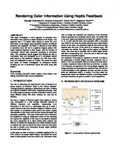
features depends on the context in which they are presented. For example, when exploring haptic shapes SineLFGauss, SineSaw and SineGauss, there was a decrease in force as the top of the sinusoidal position of the stimuli was reached, and then the sharp feature or the Gaussian lateral force provided a large increase in force. Compare this to the constant forces experienced when ascending/descending the slopes of Saw (see “Haptic Shapes” in Methods). This may not be surprising from the perceptual point of view, but it is potentially useful for haptic rendering purposes. Finally, subjects consistently matched SineSaw and SineGauss to the equivalent visual shapes: 68.9 % and 60 % of the time, respectively. Subjects’ finger trajectories during object exploration were compared to the ideal geometries of each haptic surface through Mean Squared Errors (MSEs). This allowed examining how close subjects’ finger trajectories were to the geometry of each stimulus. Fig. 6 shows a typical trajectory when exploring a SineSaw stimulus. Subjects’ finger trajectories had a slight vertical offset relative to the ideal geometry of the objects. This was due to the finite stiffness used (which in this experiment was set to 2 N/mm). The offset was eliminated before computing MSEs. MSEs were calculated within the range x ∈ (c - 0.025m, c + 0.025m ) .
TABLE I
Fig. 6. An user’s fingertip trajectory while exploring a SineSaw shape (Subject 1, trial 34).
Average Haptic to Visual matching for all subjects. The highlighted cells indicate the visual shapes to which the haptic shapes should be ideally matched. For each haptic shape, the difference in matching performance is statistically significant (ANOVA, p