Nov 13, 1991 - Indexing term: Control theory. Abstract: An integral variable structure control. (IVSC) approach for robot manipulators is pre- sented to achieve ...
Integral variable structure control approach for robot manipulators T.-L. Chern
Y.-c. wu
Indexing term: Control theory
2
Abstract: An integral variable structure control (IVSC) approach for robot manipulators is presented to achieve accurate servo-tracking in the presence of load variations, parameter variations and nonlinear dynamic interactions. A procedure is proposed for choosing the control function so that it guarantees the existence of the sliding mode and for determining the coefficients of the switching plane and the integral control gain such that the IVSC approach has the desired properties. Furthermore, a modified proper continuous function is introduced to overcome the chattering problem. The proposed IVSC approach has been simulated for the first three links of a PUMA 560 robot arm as an illustration. The simulation results demonstrate the potential of the proposed scheme. 1
Description of methodology
The IVSC approach presented here is derived for the class of second-order dynamic equations with a positivedefinite symmetric inertia matrix. Since the dynamics of most mechanical systems can be modelled in this form, this approach will have wide applications. Consider the dynamic equation [9]
M ~ + B ~ + D oW= + U
(14
where 0, 8, d are n x 1 position, velocity and acceleration vectors, respectively; M = M(0, 8) is an n x n symmetric positive-definite inertia matrix; B = B(0, 8) is an n x n matrix; D = D(0, 8) is an n x n matrix; W = W(8,8) is an n x 1 vector representing the gravity term; and U is an n x 1 control vector. The corresponding state-space model can be written as
Introduction
Most industrial robots are composed of multilinks. Such a robot arm is a highly nonlinear system with complicated coupled dynamics and uncertainty (various loads, inertia, gravitational forces etc.). With regard to such a complicated system, various controllers have been developed, such as adaptive controllers [l-31, robust controllers [ 4 6 ] and controllers based on the theory of variable structure [7-lo]. The integral variable structure control (IVSC) approach previously proposed in Reference 11 considered the single-input single-output (SISO) system and has been successfully applied to electrohydraulic servo control systems. The IVSC approach comprises an integral controller for achieving a zero steady-state error under step input and a variable structure controller (VSC) [12-141 for enhancing the robustness. With this special scheme, two control loops are obtained, and it yields improved performance when compared to conventional VSC and linear approaches [ll]. This paper extends previous results to the multi-input multi-output (MIMO) case, with an application to robot manipulators. The control of the first three links of a PUMA 560 robot arm has been simulated for illustrating the design procedure and demonstrating the robustness property.
Paper 8569D (C9, ClS), first received 21st January and in revised form 13th November 1991 T.-L. Chern is with the Institute of Electronics, National Chiao Tung University, Hsinchu, Taiwan, Republic of China Y.-C. Wu is with the Institute of Control Engineering, National Chiao Tung University, Hsinchu, Taiwan, Republic of China IEE PROCEEDINGS-D, Vol. 139, No. 2, MARCH 1992
+ [;-,]U
+ [JW
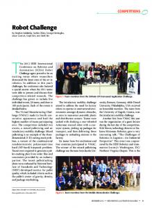
The proposed configuration of the IVSC approach is shown in Fig. 1. It combines an integral controller, a integral
cont io1ler
Fig. 1 Block diagram of an integral-variable-structure-controlled manipulator control system
VSC and the plant (eqn. I), and is described as follows:
I
e]'
where Bd = [q:e", ... represent the desired position; Z = [zIz2. . 2.1' is an n x 1 vector; I is the n x n identity matrix; K, = diag &k2 . ' . k,] is the gain matrix of the integral controller; and the control function U = [U, U , . . . U,JT is piecewise linear of the form U:(x, t ) if ui > 0 U ; ( x , t) if ui> 0
.
1=
1,
...) n
(3) 161
'
where ui is the ith component of the n-dimensional switching plane U = 0 and is chosen as ui = cAOi - kizi) + di i = 1, . . ., n
(44
or, in matrix form, C(0 - K , Z )
=
U
U
=
= diag
[UlU2
'.'
(4b)
U"]T
. . . c,] ci > 0
[clcz
Ci'O
Substituting eqn. 6 into eqn. 5 yields
ADO - M - ' ABB - AICO + AICK(Od - U) + M - ' A W + AI AT + AT
iri = - M - '
Let AW
2.1 Control function From eqns. 2 and 4,one has
+ Cd c~,(fY- e) + M - ~ W+ M - ~ U
[ A w l , ...,
=
M-' = [m;']
(i = 1, ..., n, j = 1, ..., n)
= [Adij]
(i = 1, ..., n, j = 1, ..., n)
M - ' AD
ir = - M - ' D @ - M-'Bd
M-' A B = [Abij] ( i
(5)
Let
=
1, ..., n, j
1, ..., n)
=
Each component of ir is represented as iri = (- Adi, - Aiii ci - Aiii ci ki)(Oi - ki zi)
- Abii8 + gi
M=MO+AM B=BO+AB
= (- Ad,,
W=Wo+AW
=
U,,
+ AU
=
Do@+ BO8
-
M°Cd
(64
= MOAT
( -eK , Z ) + @d + cp
Y =diag [YlY2
=Ccp,cp2
Y: Y g = {Y ;
" '
if if
-
(94
i
=
j+i
n
+ j C= ( A i i j c j K j 8 ; ' + m ; ' A w j ) +
C(AiijAzj) j= 1
1
- (Adii
+ Aiii ci + Aiii ci K i ) K iZi
(94
Then
+ Yi)(Oi- kizi)ui (10) 0;+ (8, + cpibi
+ (- Abii +
+
Y t < inf (Adii+ Aiiici Aiiiciki) if (Ui - ki zi)ui > 0 Y; > sup (Ad,, Aiii ci Aiii ciki) if (ei- k, zi)oi < 0
+
Y i=
,
1, ..., n
1, ..., n
+
i = 1, @:
mi = I=
@Jdi
and the conditions for satisfying the inequality eqn. 8 are
(64
V"1'
(ei - kizi)ai > 0 (ei - kizi)ui < 0
x ( A d i j + Aiijcj+ AiijcjKj)Oj- C ( A b i j d j ) j t i
... Y J
@ = diag [m1D2 ... O n ] cp
+ (si + vi)
ai-0
The function AU is used to eliminate the influence due to the plant parameter variations in A M , AB, AD and A W so as to guarantee the existence of a sliding mode. It is constructed as follows:
AT = ~
@i)B
+ Yi)(Oi - kizi)
lim iri ui = (- Adii - Aiii ci - Aiii ci ki
+ MOCK,(@ - U) - W o
AU where
gi =
(64
where U , , , called equivalent control, is defined as the solution of the problem U = 0 under M = MO, B = BO, D = Do and W = WO. That is, U,,
+ AT,
Aiii ci - Aiii ci k i
where
where MO, Bo, Do and W o are nominal values of M , E , D and W , and A M , AB, AD and A W are the deviations. Let the control function U be decomposed as U
-
+ ( - Abii +
D=DO+AD
162
(7)
where AI = [Aiij] (i = 1, ..., n, j = 1, _..,n ) and each entry Aiij < 1. The condition for the existence of a sliding motion on the ith switch plane is [12-141 lim ui ui < 0
Design of such a system involves (a)the choice the functions U + and U - to guarantee the existence of a sliding mode (b) the determination of the switching function U and the integral control gain K , , such that the system has the desired eigenvalues (e) the elimination of chattering of the control input.
-
+ AI
M-'Mo = I
+d
where C
For a mechanical system such as a robot arm, each diagonal component of M - ' M o is larger than the absolute value of the sum of other components in the same row [lo]. Thus, the following equation is obtained:
@;
{
..., n (lla)
< inf (Ab,,) if 4,ui > 0 i = l , ..., n ( l l b ) > sup (Abii) if 8,ui < 0
cp+suplg,l
ifui>O . I = 1, ifui