© IEEE, 2006. This is the author's version of the work. Personal use of this material is permitted. However, permission to reprint/republish this material for advertising or promotional purpose or for creating new collective works for resale or redistribution to servers or lists, or to reuse any copyrighted component of this work in other works must be obtained from the IEEE. The definite version is published in Proc. IEEE Symp. on Industrial Informatics (ISIE'06), Montreal, Canada, 2006.
Interface Design for Hardware-in-the-Loop Simulation Martin Schlager
Wilfried Elmenreich
Ingomar Wenzel
Vienna University of Technology Vienna, Austria
Vienna University of Technology Vienna, Austria
Vienna University of Technology Vienna, Austria
[email protected]
[email protected]
[email protected]
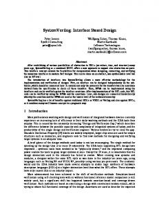
Abstract – This paper presents a scalable approach to interface between a time-triggered distributed hardware-in-theloop (HIL) simulator and the system under test (SUT) via Smart Virtual Transducers (SVTs). An SVT is an element of an HIL simulator and implements two interfaces – a standardized digital interface to a time-triggered transducer network and a transducer-specific interface. The main contribution of the approach is a separation of the execution of the simulation model and the deterministic interaction via an arbitrary transducer interface. The benefit of such separation is the temporal decoupling between simulation model execution and interaction with the SUT. Furthermore, the approach leads to a reduction of complexity of the simulation setup. The application of the approach is shown by an SVT prototype that is used to simulate a temperature sensor. I.
INTRODUCTION
Embedded applications tend to grow in size and complexity and require sophisticated test methods. One of these methods is Hardware-in-the-loop (HIL) simulation, an approach that has been introduced by the aerospace and defense industries in the 1950s [1]. At this time, the high costs of HIL technology could only be argued for systems, where human life or very expensive prototypes would have to be put at risk. In the past decade, the tremendous advances of semiconductor industry, the subsequent easy accessability of powerful computing resource to virtually every engineer and the decreasing prices of simulation hardware led to further adoption of HIL simulation to domains like industrial control applications or automotive systems. The role of HIL simulation and its benefits for the development of real-time control systems is manifold. Potential benefits are: • Testing of early system prototypes in a simulated environment becomes possible. • An ”artificial” environmental situation can be set-up that is in accordance to a defined test scenario. • Effective monitoring is possible, because control values that would be invisible for bus monitoring facilities in the system-under-test (SUT) are received by the environmental simulator (and can be further processed, logged, etc.). • Once a simulation is set-up, it is possible to perform a large number of tests with no significant cost implications.
• It is possible to develop a control system and to perform tests, even if the environment, i.e., the controlled object, is not accessible during development. • It is possible to test the behavior of a control system in hazardous situations. In the real environment it could be very costly (e.g., crash test) or even not feasible/acceptable (e.g., emergency actions of an aircraft during flight) to guide the system into such situations. This paper presents concepts for establishing the interface between the SUT and a time-triggered hardware-in-the-loop (HIL) simulator. One approach involves the concept of a smart virtual transducer (SVT) that replaces the physical transducers of the SUT without probe effect [2]. If the SUT uses a transducer network to access its transducers, we propose a gateway that performs a cluster simulation of the replaced smart transducers. A third approach to be mentioned is the physical emulation of the SUT’s environment, however this approach is elaborate and not always feasible. We present a case study that implements the first two approaches. The remainder of the paper is structured as follows: Subsequent to this introduction, section II. describes general principles of HIL simulation and specifically investigates on the coupling between an HIL simulator and the SUT. Section III. starts with a short overview of a smart transducer (ST) and thereafter elaborates the concept of a smart virtual transducer (SVT). Section IV. presents a case study with a distributed SUT and an SVT prototype. Section V. includes a short summary of the paper. II.
HARDWARE-IN-THE-LOOP (HIL) SIMULATION
Hardware-in-the-Loop (HIL) simulation is a non-intrusive test mechanism where the environment of an (embedded) SUT is simulated in order to perform tests on the SUT. In the literature, the SUT is often implemented on a single microcontroller. However, HIL simulation is not restricted to testing only a single device, but also a larger, distributed system. Figure 1 gives an overview of the basic parts of an HIL simulation. The outputs of a so called HIL simulator are used as inputs to the SUT. The outputs of the SUT are used as inputs to the HIL simulator. With HIL simulation, the SUT is usually regarded as a black box. Thus, only the interfaces of the SUT to its environment are relevant. The HIL simulator provides simulation values to the SUT and monitors the reaction of the SUT, i. e., receives the outputs of the SUT.
• The HIL simulation should be scalable and open. • The HIL simulation should be of reasonable cost in terms of HW/SW components and development time. In the following we will elaborate the concept of an SVT that supports the above mentioned considerations. C. Fig. 1: Basic parts of HIL simulation
In a pure software simulation which is sometimes also referred to as software-in-the-loop (SIL), no embedded hardware of the SUT is involved. In contrast to a pure software simulation, HIL simulation allows to observe the actual influence of the hardware characteristics of the SUT which includes the physical behavior of hardware signals and the execution of the SUT in realtime. Thus, testing with an HIL simulation is closer to the real application than a pure software simulation. Furthermore, HIL simulation can be applied in cases where protected intellectual property (IP) is involved. For instance, continuing changes of control algorithms in present traffic controllers and the need for manufacturers to maintain propriety is mentioned in [3] as a key benefit for HIL simulation in the transportation systems domain. A. Open loop vs. closed loop HIL simulation We can distinguish between the two following approaches for HIL simulation: Open loop HIL simulation: When HIL simulation is performed in an open loop, the generation of simulation data by the HIL simulator is independent of the previous output data of the SUT. The output of the SUT is only captured for future evaluation purposes but has no influence on the simulation data. Therefore, in an open loop scenario, the input data for the SUT can also be calculated off-line. Closed loop HIL simulation: In a closed loop scenario, the previous output of the SUT directly influences the calculation of subsequent input data. Thus, the simulation data must be calculated by the HIL simulator during runtime, i. e., in real-time. B.
Aspects to be considered for an HIL simulation
When setting up an HIL simulation, several aspects have to be taken into consideration. In [4] five key factors are mentioned which are: • The HIL simulation should accept a variety of SUT configurations. • A small change in the SUT must not require complete redesign of the HIL simulation. • The HIL simulation should be able to perform both open and closed-loop testing.
Coupling of HIL simulation and SUT
The SUT would normally interface its environment by means of transducers, i. e., sensors and actuators. Inputs of the SUT would be captured by sensors, outputs of the SUT would drive actuators. Thus, the coupling between the HIL simulator and the SUT can either be established by emulating the transducer interface (i. e., the interface between SUT and transducer) or by direct interaction with the physical transducers of the SUT. Figure 2 depicts three possibilities of interfacing the SUT. In case a), the interfaces to the physical sensors or actuators are emulated by an SVT. The X over the transducers of the SUT indicate, that these are not present in the HIL configuration. In many cases, the SVT has to generate or consume analog signals (in value and/or time domain), which affects the reproducibility of a test run. On the other hand, this approach affords minimal intervention with the SUT and thus avoids probe effects at the SUT. There are many different examples of transducer-specific interfacing schemes like for instance the range of an analog signal that represents the measurement of an infrared sensor, the response behavior of an ultrasonic sensor, or a PWM signal for an electrical motor. For coupling via transducer-specific interfaces, different approaches can be found in literature. These range from specific examples that are tailored to a certain class of transducers to generic reconfigurable devices like for instance the PXI-7831R FPGA I/O board from National Instruments [4]. In Figure 2 b), we assume that the SUT accesses its transducers via a digital transducer network interface. In this case, we use a gateway node that emulates the smart transducers of the SUT that are not present in the HIL configuration. If the interface between SUT and transducers is a predictable digital real-time network, the reproducibility of test runs is guaranteed. Thus, this approach is preferable over variant a), however it requires that the SUT has an appropriate transducer network interface, thus being less flexible than a). An example for coupling an HIL simulator with the SUT via the OMG standardized smart transducer interface (OMG STI [5]) is given in [6]. Approaches a) and b) are usually chosen, when the physical transducer is not available or a certain test scenario can not be established by interfacing the transducer. For example, if a fault injection campaign involves transducers to exhibit a particular erroneous behavior, the use of real transducers is problematic. Figure 2 c) depicts a configuration, where the SUT physically keeps its transducers. In case of a sensor, the HIL simulator has to drive an actuator that physically interacts with the sensor of the SUT. In case of an actuator, the HIL simulator has to measure the actions of the actuator via a sensor that is connected to the
of design principles for smart transducers as well as the comparison of two smart transducer interface standards, i. e., IEEE 1451.2 and OMG STI, is presented in [9].
Fig. 3: Smart Transducer (Atmel 4433 microcontroller and Sharp IR distance sensor, scale in cm) Fig. 2: Interfaces between HIL simulator and SUT
HIL simulator. The benefit of interfacing the SUT via a physical transducer is that no behavioral model of the physical transducer is required. Thus, the coupling via the physical transducer is the preferred approach, when it is infeasible (technically or economically) to set up a sufficiently accurate model of the transducer. In [7], an HIL simulator for an aerospace application (autopilot) is mentioned that physically interfaces the SUT via an elevator servo. Instead of modeling the internal physical behavior of the elevator servo, the deflection of the physical servo is read from a feedback potentiometer. III. CONCEPT OF SMART VIRTUAL TRANSDUCER Smart virtual transducers (SVTs) are dedicated to an HIL simulation setup where the coupling between the HIL simulator and the SUT is established via different transducer-specific interfaces (as represented by figure 2 a)). The concept of a smart virtual transducer is closely linked to the concept of a smart transducer. Thus, we will start with a brief explanation of smart transducers. A. Smart Transducer An intelligent or smart transducer is the integration of an analog or digital sensor or actuator element, a processing unit, and a communication interface. In case of a sensor, the smart transducer transforms the raw sensor signal to a standardized digital representation, checks and calibrates the signal, and transmits this digital signal to its users via a standardized communication protocol [8]. Figure 3 depicts a smart transducer with an Atmel 4433 microcontroller as processing and communication unit and a Sharp IR distance sensor as physical sensor element. A closer description
B.
Smart Virtual Transducer
In contrast to a smart transducer (ST), a smart virtual transducer (SVT) does not contain a physical sensor or actuator element. Instead, an SVT is used to emulate a sensor or actuator element. Thus, an SVT consists of a processing unit, a communication interface, and a transducer specific interface. An SVT is either used to emulate the behavior of a physical sensor or to emulate the behavior of a physical actuator. Thus, an SVT acts either as a virtual sensor or as a virtual actuator. The concept of an SVT is not specifically tailored to a certain target system and can thus connect to any ”black box” without having knowledge about the internal design of the ”black box”. This ”black box” can e. g., be a smart transducer (without transducer element) as depicted in figure 4 or an arbitrary electronic control unit (ECU). From the perspective of an SVT, only the transducer interface is relevant. The possibility to connect to any kind of target system hardware allows a wide variety of SVT simulation scenarios. An SVT that emulates a sensor must be provided with simulation data by a dedicated simulation host (refer to figure 2), an SVT that emulates an actuator provides actuator data to the simulation host. The simulation host can either be implemented as a transducer node and participate in the transducer network, or it can be implemented as a more complex and powerful hardware unit that is connected to the transducer network via a gateway node. Communication between SVTs and the simulation host is handled via the standardized transducer communication interface OMG STI [5]. The OMG STI allows deterministic communication, with a predefined update rate of transmitted data between the simulation host and the SVTs. Communication between the SVT and the SUT via the transducer interface of the virtual transducer requires more sophisti-
However, we must take assumptions on the maximum change rate of the environment variables consumed and manipulated by the SUT, since the SVT must be fast enough to keep up with changes in the environment. The environment variables must be communicated to the SVTs at least with the Nyquist rate [10], while the SVT performs a local filtering and extrapolation of the data to be fed to the SUT. C.
Temporal decoupling of SVT elements
The requirement of independence (temporal decoupling) between the virtual transducer with its interface to the target system and the remaining parts of the SVT leads to the following partitioning within an SVT: SVT logic with communication interface: The digital communication interface is responsible for deterministic exchange of messages within the HIL simulator. In case the SVT is configured to act as a virtual sensor, the SVT logic receives simulated sensor values and regularly adjusts the virtual sensor. In case the SVT is configured to act as a virtual actuator, the SVT logic reads the actuation parameters of the virtual actuator and forwards the values to the HIL simulator.
Fig. 4: Elements of a Smart Virtual Transducer (SVT)
cated inspection. Requests from the target system to perform a sensor reading of a virtual sensor or to set a virtual actuator are not under control of the SVT. Such a request can e. g., be the reading of a D/A value (virtual IR sensor), measuring the delay of a response (virtual ultrasonic sensor), setting a PWM signal (virtual PWM actuator). Regarding predictability of the occurrence of requests from the target system, we have to distinguish between two different cases: Synchronized: The HIL simulator, i. e., the SVT network, is synchronized to the SUT and has a priori knowledge about the instants when the SUT reads its sensors or updates its actuators. In order to achieve this, the design of the SUT has to be known to the extend of the timing of all possible task activations of tasks that access the transducers. Unsynchronized: The SUT is handled as a black box; we assume that the SUT can access a virtual transducer at any point in time. Therefore, the SVT has to provide a valid sensor value at any instant and, respectively, has to log new actuator settings instantly. While the synchronized approach eases the design of the SVT and supports replicable results at least in the time domain, the unsynchronized approach is more flexible since it supports any SUT without requiring knowledge about its internal timing.
Virtual transducer with VT interface: The transducer interface of the virtual transducer shall resemble the interface between the target system and a particular transducer, which would be expected by the target system. Thereby, the value domain as well as the time domain must be considered. Especially for applications that use the response time of a sensor for the calculation of a measurement (e. g., ultrasonic sensor), the timeliness of the virtual transducer response is important. D.
Types of SVTs
We distinguish between two types of SVTs: (a) SVTs that mimic the behavior of a sensor, i. e., smart virtual sensor and (b) SVTs that mimic the behavior of an actuator, i. e., smart virtual actuator. Physical sensor devices can offer sensor data in the value and/or in the time domain. Both kinds of sensors must be reflected by a smart virtual sensor. An example of a sensor that delivers sensor data in the value domain is an infrared distance sensor. The processing unit that interfaces the IR distance sensor receives an analog signal from the sensor that reflects the last measured distance. An example of a sensor that delivers sensor data in the time domain is an ultrasonic sensor. An ultrasonic sensor is triggered by a processing unit to send out an acoustic signal. As soon as the acoustic signal is echoed back to the sensor, the sensor informs the processing unit about the reception of the acoustic signal. The processing unit calculates the time from sending the signal until the reception of the signal in order to get a distance measurement. Similar to sensor devices, physical actuator devices require distinguishing between value and time domain. There are many different devices that can be operated by setting an analog
Fig. 5: Case study with a distributed SUT
value (LEDs, simple electric motors, . . . ). However, also timedependent signals must be taken into account. An application could send for instance a PWM signal to drive an actuator. For our prototype in section IV., we decided to build a smart virtual sensor that is capable to emulate sensors that operate in the value domain. Support for sensors that operate in the time domain is planned for a future implementation. E. Update Rate at Virtual Transducer Interface The update rate of transducer data that is sent via the transducer interface of the virtual transducer can be greater than the update rate of transducer data that is transmitted via the communication interface of the SVT. In case it is not sufficient to take the last transmitted value, more sophisticated services can be realized by the SVT logic. Examples for such services are interpolation or extrapolation functions for a smart virtual sensor or the average of several actuation values for a smart virtual actuator. F.
Benefits of our approach
The concept of SVT leads to a separation of concerns and thus to a reduction of the mental complexity when setting up an HIL simulation. The simulation model that is executed at the simulation host is decoupled from the specific SVT elements that interact with the SUT. Thus, it is not necessary to include the behavior of a certain transducer element in the simulation model at the simulation host. Changes of transducer elements (e. g., upgrade of a transducer to a newer model) do not directly influence the simulation model because the behavior of the transducer is hidden by the SVT. A re-design of the simulation model can in general be avoided. The separation of the execution of the simulation model and the interaction between HIL simulator and SUT also leads to temporal decoupling (temporal firewall), i. e., a simulated value is required to be available within a certain time interval but not at
a certain point in time. Furthermore, monitoring of timing violations of the execution of a simulation model can be easily performed by an SVT. Another aspect supported by the SVT approach is reusability. Since the implementation of a SVT mainly depends on the transducer that is replaced, an SVT can be reused in other applications whenever the same kind of transducer is employed. Although features like the frequency of the update value and smoothing parameters depend on the control environment, these functions can be generically implemented and parametrized for a particular application. The presented approach is scalable in the sense that it is not restricted to a certain amount of participating SVTs within an HIL simulator. The use of a standardized interface for the communication with the simulation host allows easy adaption of existing simulation setups. The approach is open to any kind of ”black box”, i. e., any transducer-specific interface can be implemented on an SVT. Thus, integration tests, both open loop and closed loop, of a wide variety of SUT configurations can be performed with our approach. The cost of the HW components of an HIL simulator with SVTs is pretty low. The simulation host can be implemented on a standard desktop computer and the SVT elements are inexpensive (a few euros per SVT). IV.
CASE STUDY
The case study involves a distributed SUT that consists of three nodes interconnected by a TTP/A fieldbus system [11]. Figure 5 depicts the components of the case study. The control node contains a PI controller and two analog sensor interfaces, one for the actual value and one for the setpoint value. The first sensor interface is identical to the interface of a LM335Z temperature sensor from National Semiconductor. The other sensor
interface is connected to a potentiometer that gives the setpoint value. The display node receives the actual value, the set value and the setpoint value from the network and displays them at a 7-segment display. Another node acts as TTP/A master, a necessary time source in TTP/A networks. The actual target system would also have an actuator (heating element) with a TTP/A interface, in our setup this node is omitted and replaced by a simulated node. The TTP/A network is used to broadcast the actual value (8 bit), the setpoint value (8 bit) and the set value (16 bit) by the control node. The display node receives all three values, the gateway of the simulation requires only the set value. The communication bandwidth is 19200 bit/sec; the cycle time of the cluster is 16,25 ms. The simulation host does not influence the communication behavior of the SUT, thus there is no probe effect on the system. The simulation host is connected to the SUT by two different ways: The temperate sensor interface is connected by an SVT that emulates the physical electric interface of the LM335Z. Furthermore, the simulation host emulates an actuator node on the bus that reads and executes the set value. The simulation host simulates a simple control path whereas the set value from the TTP/A bus acts as input to the control path and the resulting value is converted into an analog signal and forwarded to the control node. The simulation system has been implemented in a compact way on a node with a TTP/A network interface, an Atmel AVR Atmega168 microcontroller node and an AD5330 digital/analog converter from Analog Devices. Figure 6 depicts the hardware used for the simulation system. In future applications this node will be used as an SVT within a network of SVTs and a more powerful simulation host.
The main contribution of the presented approach is the separation of the simulation model execution and the deterministic interaction between the HIL simulator and the SUT via an arbitrary transducer interface – thus, reducing mental complexity and achieving temporal decoupling between simulation model execution and interaction with the SUT. VI.
ACKNOWLEDGMENTS
This work has been supported in part by the Austrian FWF project TTCAR under contract No. P18060-N04 and by ¨ DOC [ DOKTORANDENPROGRAMM DER OSTERREICHISCHEN AKADEMIE DER WISSENSCHAFTEN ]. REFERENCES [1] S. Nabi, M. Balike, J. Allen, and K. Rzemien. An overview of hardware-in-the-loop testing systems at Visteon. SAE technical paper series, SAE International, 400 Commonwealth Drive, Warrendale, PA 15096-0001 USA, March 2004. [2] C. E. McDowell and D. P. Helmbold. Debugging concurrent programs. ACM Computing Surveys, 21(4):593–622, December 1989. [3] Z. Li, M. Kyte, and B. Johnson. Hardware-in-the-loop real-time simulation interface software design. In Proceedings of the IEEE Intelligent Transportation Systems Conference, pages 1012–1017, Washington, D.C., USA, October 2004. [4] National Instruments. LabVIEW FPGA in hardware-in-the-loop simulation applications, 2003. [5] OMG. Smart Transducers Interface V1.0. Available Specification document number formal/2003-01-01, Object Management Group, Needham, MA, U.S.A., January 2003. available at http://doc.omg.org/formal/2003-01-01. [6] M. Schlager. A simulation architecture for time-triggered transducer networks. In Proceedings of the First Workshop on Intelligent Solutions for Embedded Systems (WISES’03), pages 39–49, Vienna, Austria, June 2003. [7] M. Gomez. Hardware-in-the-loop simulation. Available at http://www.embedded.com, November 2001. Embedded Systems Programming, CMP Media LLC, 600 Harrison Street, San Franzisco, CA, 94107.
Fig. 6: Prototype of a Smart Virtual Transducer with D/A Converter
V. CONCLUSION In this paper, we presented an approach for the coupling of a hardware-in-the-loop (HIL) simulator and the respective system under test (SUT) via so called smart virtual transducers (SVTs). We started with a brief investigation on benefits and basic concepts of HIL simulation. Focus was on the coupling between HIL simulator and SUT. Such coupling can be established via the transducer interface or via a physical transducer. The concept of an SVT offers coupling of an HIL simulator with the SUT via an arbitrary transducer interface. We concluded the paper with a case study that presented an SVT prototype.
[8] H. Kopetz, M. Holzmann, and W. Elmenreich. A universal smart transducer interface: TTP/A. International Journal of Computer System Science & Engineering, 16(2):71–77, March 2001. [9] W. Elmenreich and S. Pitzek. Smart transducers – principles, communications, and configuration. In Proceedings of the 7th IEEE International Conference on Intelligent Engineering Systems, volume 2, pages 510–515, Assuit – Luxor, Egypt, March 2003. [10] H. Nyquist. Certain topics in telegraph transmission theory. Transactions of the A.I.E.E., 47:617–644, February 1928. [11] F. Skopik, M. Wihsb¨ock, and W. Elmenreich. Anbindung einer Regelstreckensimulation an ein zu pr¨ufendes System mittels eines Smart Inverted Transducers. Research Report 2/2006, Technische Universit¨at Wien, Institut f¨ur Technische Informatik, Treitlstr. 13/182-1, 1040 Vienna, Austria, 2006.