a multicast extension to the DTN's unicast PROPHET protocol. A multicast protocol .... (Global Positioning System), they may only know the region they are in by.
Multicast in Delay Tolerant Networks using Probabilities and Mobility Information José Santiago, Augusto Casaca and Paulo Rogério Pereira INESC-ID/IST R. Alves Redol, 9, 1000-029 Lisboa, Portugal e-mails: {jose.santiago, augusto.casaca, paulo.pereira}@inesc-id.pt
Abstract. Networks with frequent and long duration partitions prevent common Internet protocols from working successfully. For protocols to work properly in these Delay/Disruption Tolerant Networks (DTNs), a new protocol layer was proposed that acts on top of the transport layer for the end-to-end exchange of messages (called bundles) taking advantage of scheduled, predicted, opportunistic or permanent connectivity. In this paper, we propose and evaluate a multicast extension to the DTN’s unicast PROPHET protocol. A multicast protocol is useful to reduce the number of copies of packets when they are sent to multiple destinations. PROPHET routes packets based on estimates of the probability of nodes meeting. We show by simulation that by using just one byte for transferring mobility information between nodes, a good clue is given about the region where mobile nodes are, which can be used by the multicast protocol to decide where to forward messages. Additionally, we show that if the number of contacts between nodes is above a minimum threshold, a pseudo multicast tree will exist, multicast works efficiently and message replications are minimized. Key words: Delay/Disruption Tolerant Networks, Connection Disruption, Multicast.
1
Introduction
Delay Tolerant Networks (DTNs) are networks that may experience frequent and long duration partitions. This occurs in situations in which no stable infrastructure exists that can guarantee permanent link connectivity. Examples of these situations are: military communications in the battlefield, deep space communications and rescue actions in catastrophe hit areas. The Internet protocols are not useful for DTNs because link disruptions are not properly handled, causing protocols to timeout and abort. The DTN Research Group (DTNRG), which was chartered as part of the Internet Research Task Force (IRTF), has proposed an architecture [1] and a communication protocol [2] (the Bundle Protocol) for DTNs. In DTNs, a message-oriented overlay layer called “Bundle Layer” is added. The Bundle Layer exists above the transport (or other) layers of the networks it interconnects. Application data units are transformed by the Bundle Layer into one or
2
José Santiago, Augusto Casaca and Paulo Rogério Pereira
more protocol data units called "bundles", which are forwarded by DTN nodes according to the Bundle Protocol. To help routing and scheduling decisions, bundles contain an originating timestamp, useful life indicator, a class of service designator and a length indicator. The Bundle Protocol includes a hop-by-hop transfer of reliable delivery responsibility, called bundle custody transfer, and an optional end-to-end acknowledgement. Persistent storage may be used in DTN nodes to help combat network interruption. The Bundle Protocol does not include a bundle routing protocol nor mechanisms for populating the routing or forwarding information bases of DTN nodes. These functions are left for protocol extensions or for other protocols. One of the important routing protocols in DTNs is Epidemic Routing [3], which works by flooding the network with the messages. Although it provides the optimal solution for DTNs as regards the delivery ratio and latency, it is very wasteful of resources. The PROPHET (Probabilistic Routing Protocol using History of Encounters and Transitivity) protocol [4] is a routing protocol for unicast communication in DTNs. The DTN PROPHET Protocol (DTN-PP) uses the history of encounters between nodes and transitivity to estimate the probability of nodes meeting and exploits the mobility of some nodes to bring messages closer to their destination. The DTN-PP is an alternative to Epidemic Routing with lower demands on buffer space and bandwidth, with equal or better performance in cases where those resources are limited and without loss of generality for scenarios where it is applicable. Multicast communications are used when data is to be sent efficiently and simultaneously to a group of destinations, creating copies of the data not in the source, but only as required by the paths to the destinations. Extensions to the Bundle Protocol for supporting multicast are defined in [5]. No multicast routing strategies are yet defined, just the basic mechanisms for supporting multicast. An overview of multicast models for DTNs is presented in [6], but no specific protocol is proposed. In [7], we proposed the Multicast over DTN-PROPHET Protocol (MoDTN-PP) as an extension to DTN-PP for non-custodial multicast. Non-custodial, by itself, means that the protocol will do its best effort to deliver messages. No node assumes custody for bundles being transmitted to the destination, so no special actions will be done to assure success. The probabilistic model from DTN-PP for node contacts was kept in MoDTN-PP. A pseudo-multicast tree mechanism was added to manage multicast groups. [8] proposes several extensions to handle custody transfer that may be added to multicast routing protocols for DTNs. In this paper, we describe how indications of the location and direction of the moving nodes are introduced in MoDTN-PP to help forming a pseudo multicast tree [9]. We show that DTNs can benefit with multicast communications when certain requirements are respected. We demonstrate that if there are a minimum number of contacts between nodes, multicast works efficiently, minimizing the number of message replications done in the network. Section 2 of the paper summarizes the main aspects of probabilistic routing in DTN-PP. Section 3 provides an overview of the DTN-PP extensions for multicast. Sections 4 and 5 are dedicated to the simulation goals and results. Finally, section 6 presents conclusions and further work topics.
Multicast in Delay Tolerant Networks using Probabilities and Mobility Information
2
3
The DTN Prophet Protocol Probabilistic Model
DTN-PP uses the concept of probabilistic routing instead of epidemic routing, exploring the predictability of opportunistic contacts for message dissemination. In DTN-PP, the calculation of the delivery predictability is done in three parts as shown in the equations below. P(x,y) is the delivery or contact probability from node x to node y, which is used as a routing metric. 0 ≤ Pinit ≤ 1.
(1)
P(a,b) = P(a,b)old × γk;
0 ≤ γ < 1.
(2)
P(a,c) = P(a,c)old + (1- P(a,c)old) × P(a,b) × P(b,c) × β;
0 ≤ β ≤ 1.
(3)
P(a,b) = P(a,b)old + (1- P(a,b)old) × Pinit;
Equation (1) is for probability update whenever two nodes meet: it will increase P(a,b) every time they meet, since nodes that contact frequently have a higher probability to exchange messages. P(a,b)old is the last previous calculation in node ‘a’. Pinit is an initialization constant that controls the rate of probability increase. Equation (2) lowers the P(a,b) probability as time passes, being used whenever the tables are updated. If contacts are rare, the probability should be reduced to reflect this. γ is an aging constant. k is the number of time units that have elapsed since the last time the metric was updated. Equation (3) expresses transitivity, as messages can go from “a” to “c” directly or via “b”. If “b” frequently meets “c”, then it is probably a good node for forwarding messages to “c”. β is a scaling constant that models the impact the transitivity should have on the delivery predictability. This probabilistic model was kept in MoDTN-PP.
3
Multicast over DTN-Prophet Protocol
MoDTN-PP adds multicast message delivery capabilities to DTN-PP. MoDTN-PP introduces the use of mobility information, which is an innovative point compared with DTN-PP. This means that MoDTN-PP can use the information of the node position and of its moving direction in addition to the estimate of the probability of contact between nodes from DTN-PP. 3.1
Mobility Information Mechanism
Contacting nodes need to exchange the following control information: − Contact probability of nodes which move in the same area; − Their own geographical position and the geographical position of the nodes they contacted; − Their moving direction and the moving direction of the nodes they contacted.
4
José Santiago, Augusto Casaca and Paulo Rogério Pereira
This additional information can be carried in just one byte. The convention used is as follows: − The two most significant bits carry the direction information; − The three following bits carry the x coordinate; − The last three bits carry the y coordinate. The moving direction of a node identifies the approximate direction the node is heading to as the quadrant into which the node is moving to (identified with a number between 0 and 3). If the node is stopped or moving in the border between quadrants, then any of the quadrants involved may be reported. Of course, the moving direction can change, but this is not known beforehand. This relevant information is complemented with the approximate global position coordinates (referred to the total area), at the moment in which the node contact happens. With this method, the mobile's position and direction passed to a peer are not completely precise. However, for most situations it is enough to introduce efficiency in the system. Indeed, nodes can be always moving and connections are difficult. Their actual position cannot be delivered instantaneously to the entire network. When this information is propagated, it may become obsolete very fast, so it is not very important to be completely accurate. As a matter of fact, a system will be more costeffective if it consumes fewer resources and just gives good clues about the region where a mobile node shall be found. In addition, unless mobile nodes have GPS (Global Positioning System), they may only know the region they are in by identifying some wireless access point in the neighbourhood or by getting their position from adjacent nodes. 3.2
Information Exchanged During Nodes Contact
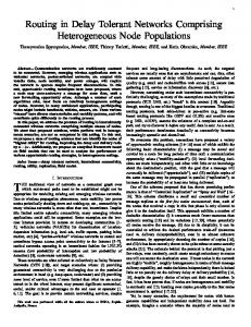
When nodes establish contact, they exchange two types of information: routing and data. All the mechanisms related with unicast routing from DTN-PP were kept in the multicast extension. As shown in Fig. 1, after the nodes establish contact and exchange Hello and Acknowledgement messages, nodes exchange a Routing Information Base Dictionary (Dict) that includes the address list used to make routing decisions for all known destinations. Nodes also exchange their Routing Information Base (RIB), where contact probabilities are stored. The mobility information added in MoDTN-PP was inserted in the Hello messages for the nodes sending the messages, and into the RIB for other nodes. After the exchange of Dict and RIB messages, nodes send an offer message with the list of bundles they have. Then they wait for request messages and send data messages with the bundles requested. Some small modifications were made to the DTN-PP state machines to stop sending periodic messages when there is no more useful information to exchange, saving energy. Also, a new field for multicast mode usage was proposed in [10] to be added to the Bundle Protocol messages. This field carries the previous hop identity, which permits a node to determine the shortest path to the source. In this way, loops can be prevented. This field was also added to the MoDTN-PP implementation.
Multicast in Delay Tolerant Networks using Probabilities and Mobility Information
Node 1 Hello(SYN)1
Node 2 Hello(SYN)2
Hello(SYNACK)1 Hello(SYNACK)2
Node 1
Hello(ACK)1
Hello(ACK)2
Node 2
Dict1
Dict2
RIB1
RIB2
Offer1
Offer2
Req1 data1
5
Req2
data2
Fig. 1. Information exchanged during nodes contacts.
3.3
Pseudo Multicast Tree
In traditional multicast, a well-defined tree is created whenever a group interested in the communication is active. This tree connects all members of the multicast group to a point in the network. This point can be the source or another point called rendezvous point (RP). In the first case, the tree is called a source-based tree and in the second case it is known as a shared tree. For DTNs, such trees cannot be created permanently. Connections between nodes may have a very short duration, so an all-way active path from the source (or RP) to one or more destinations through a considerable number of nodes is not expectable. As a consequence, in DTNs, the concept of a multicast tree is broader. This pseudo multicast tree will be composed by one source (or RP) and a set of destinations with a set of intermediate nodes (mules) between them. Mules get data packets from sources - or RPs - or other mules and forward them to destinations points. When a node needs to join a multicast group, it uses the best of its neighbours to contact the group. The choice is made with a heuristic based on the conditions of neighbours as shown in Table 1. Every condition is evaluated based on the available information at the moment. The weight of every condition that is true is added. An additional bonus varying from 15 to 0, according to how old the information was received from that particular neighbour is also added. The bonus of 0 is for information older than 4 minutes. The neighbour that has a higher final result is selected. The weights were chosen to value connections as direct as possible to the source. This is the reason the largest weight (30) is for a direct connection to the multicast source. The second largest (14) is for a neighbour already contributing to the multicast tree operation. The third weight (10) is for a neighbour that can contact
6
José Santiago, Augusto Casaca and Paulo Rogério Pereira
the multicast source with high probability. The fourth weight (6) is to distinguish from the case where this probability is zero. The remaining conditions are for giving preference to good contacts with neighbours, to neighbours near the source, to neighbours moving near the source or to neighbours that can contact any member of the multicast group. These weights were chosen intuitively and proved to produce good results. The study of other parameters or heuristics was left for further work. Table 1. Criteria for selecting a neighbour for inclusion on the multicast tree Weight 30 14 10 6 4 3 2 1
Condition of neighbour is the source of the group is a group member, or already serves as a mule has/can contact the source with P(x,y)>=0.7 has/can contact the source with 0 P(A,D). When two nodes meet, a bundle is sent to the other node if the delivery predictability of the destination of the bundle is higher at the other node. The first node does not delete the bundle after sending it, as long as there is sufficient buffer space available (since it might encounter a better node, or even the final destination of the bundle in the future). GRTRsort - Select bundles in descending order of the value of P(B,D)-P(A,D). Forward the bundle only if P(B,D) > P(A,D). This strategy is like GRTR, but instead of just going through the bundle queue linearly, this strategy looks at the difference in delivery predictabilities for each bundle between the two nodes, and forwards the bundles with the largest difference first. As bandwidth limitations or disrupted connections may result in not all bundles that would be desirable being exchanged, it could be desirable to first send bundles that get a large improvement in delivery predictability. Direct - Bundles are delivered only when its end-destination is contacting with the source. Some of these forwarding strategies will be used and evaluated in the simulations shown in Section 5.
8
4
José Santiago, Augusto Casaca and Paulo Rogério Pereira
Simulation Conditions and Goals
In order to evaluate MoDTN-PP, we had to recreate the conditions in which DTN-PP was tested. It is important to test MoDTN-PP in the same conditions in which DTN-PP proved to work well. In this way, it can both be observed if its performance was affected and if unicast and multicast modes performed satisfactorily. 4.1
Test Scenario Definition
Two scenarios used in the DTN-PP evaluation [11] were reproduced. The first scenario was generated using the Random Waypoint Mobility Model [14], which is a model commonly used by the scientific community, and the second scenario is based on the Community Model [11], which was originally created for DTN-PP tests. For the sake of the evaluation, the main parameters of the DTN-PP mobility models were preserved. This means that, for both cases, hereafter referred to as Scenario_1 and Scenario_2, respectively, the parameters used and shown in Table 2 were strongly based on those defined in [11]. Table 2. Specification of the scenarios
Parameters Area Total number of nodes Speed Pause time Warm up period Message generation period Simulation duration
Scenario_1 1500 m × 300 m 50 0 – 20 m/s 5 – 13 s 500 s 1980 s 4500 s
Scenario_2 3600 m × 1500 m 50 10 – 30 m/s 5 – 13 s 500 s 3000 s 11500 s
Parameters in Table 2 have literal meanings. “Area” represents the geographical area in which mobile nodes move; “Speed” indicates the limits between which the mobile speed varies and “Pause time” is the time range during which the mobile stops when it arrives at a new position. “Warm up period” represents the moment at which messages begin to be generated after the start of the simulation (the warm up period is needed to allow the DTN-PP delivery probabilities to have initial values). The message generation stops when the “Message generation period” is elapsed. Besides the differences between both scenarios shown in Table 2, there are other differences related to the mobility model used in each of the scenarios. In Scenario_1 all nodes move randomly. The movement of each node starts by randomly selecting a new direction and position. As the node arrives at that position, it stops for a period of time randomly selected between 5 and 13 seconds. After that, it repeats the procedure to move to another place. The Community model has a different philosophy. Although the node, after arriving at a certain position, also stops for a period of time between 5 and 13 seconds, in this case the geographic area of Scenario_2 is divided
Multicast in Delay Tolerant Networks using Probabilities and Mobility Information
9
into 12 sub-areas as in [11]. Each represents a community place. The last sub-area is the “Gathering place”. In each of the 12 sub-areas there is a community static node that helps message exchange between mobile nodes. Sub-areas from 0 to 10 are homes for the nodes. The number of resident nodes may vary from 3 to 6 in each subarea. Finally, node destinations are selected probabilistically as shown in Table 3. Selecting a destination means: if a node is at “Home”, 0.8 represents the probability of the “Gathering place” to be its next destination and 0.2 is the probability for the node to go elsewhere; in the same way, the probability for the node to go “Home” when it is “Elsewhere” is 0.9, and only 0.1 to move to another sub-area. Table 3. Destination selection probabilities
From/To
Home
Home Elsewhere
0.9
Gathering place 0.8 -
Elsewhere 0.2 0.1
The reasons for creating a scenario such as the Community Model are given by its authors. In their own words, this kind of scenarios, where mobility can occur, involves human mobility in communities represented by villages and larger towns. Furthermore, towns themselves can represent the gathering place to and from which people resident in the surroundings move to work every day. Another rural example used for this gathering place model is a feeding ground where shepherd communities conduct animals with sensors attached to them. Indeed, projects like ZebraNet [12] and other related to semi-nomadic Saami population of reindeer herders [13], in the north of Sweden, were inspired for seemingly realities. Other differences between the two scenarios are related to traffic. In Scenario_1 a message is sent every second from any node belonging to a subset of forty-five sources. If the message must be delivered in unicast mode, the source is selected randomly and the destination will be any node belonging to the remaining forty-four nodes. However, if the message must be delivered in multicast mode, the message is only distributed to the other members of the group (in our case, 8 nodes). A ninth node acts as the multicast group source. Only one multicast group was active in the simulations. The group is identified by the association of two addresses: the source address and the group address. In Scenario_2, multicast messages have the same source and end-destinations as in Scenario_1. However, unicast is generated in a different way when compared with the first scenario. In Scenario_2, two randomly selected community static nodes send one message every ten seconds for static nodes located in other communities. Every time, five seconds later, two randomly selected mobile nodes send one message to randomly selected destinations. Three kinds of message delivery modes were used simultaneously: i) unicast, where a message is sent to a single destination; ii) multicast, where a message is sent to all members of a group of destinations with a reduced number of message replications; and iii) multidest, where independent copies of the source message are sent in unicast to every destination of a group of destinations. In both scenarios, the number of unicast bundles generated is about 2/3 of the generated bundles, while multicast and multidest
10
José Santiago, Augusto Casaca and Paulo Rogério Pereira
bundles were configured each one to be about 1/6 of the total. These values ensure a significant proportion of multicast, but still keeping unicast traffic dominant. Finally, the parameter values used to test MoDTN-PP were kept exactly as in the original protocol scenarios. These parameters are defined in the protocol to calculate contact probabilities between nodes as seen in section 2. The parameter values used are shown in Table 4. Other simulation parameters are shown in Table 5. Table 4. MoDTN-PP parameters
Parameter Pinit β γ
Value 0.75 0.25 0.98
Table 5. Other simulation parameters
Parameter link bandwidth queue size 4.2
Value 250 kBytes/s 1000 packets
Measuring Goals
The main goals of the evaluation are to verify under which conditions multicast in MoDTN-PP works and to assess its performance as compared to unicast and multidest communications. Multidest is also used to confirm that multicast improves performance by reducing message replication. Being wireless communication a subjacent goal, the evaluation criterion used is based on the wireless link range. Considering the link range used by many equipments operating in the wireless area, one hundred meters was selected as an average value: 60m and 160m limit the test interval. In this kind of simulation, the variation of the link range corresponds directly to the variation of the number of node contacts. This effect could be also achieved by varying the number of nodes in each simulation. In both cases, the number of opportunities for nodes to exchange messages is linearly related to the number of nodes or to their wireless link range. However, modifying the link range is easier to simulate than modifying the number of nodes. The performance is measured by the bundle delivery ratio (received messages/registered messages) and the average bundle delay. As a supplementary goal of the evaluation, it is also important to analyse how the multicast trees succeed, if they succeed, while the system works. Indeed, a starting point for this analysis is the fact that multicast trees cannot permanently exist in presence of multiple and frequent link disruptions. This means that it is not expected to have an end-to-end path that ties the multicast group source to all group members, through some intermediate nodes. This is a principle for DTN networks, and cannot be ignored while trying to use the multicast mode. However, another system principle is that there are a large enough number of nodes that move. Moreover, there are
Multicast in Delay Tolerant Networks using Probabilities and Mobility Information
11
regularities in these moves that facilitate encounters among nodes. Some sub-group of these nodes will maintain more or less longer contact as they move in a similar direction. If these same nodes are members of a multicast group, they can form a multicast tree branch acting as a bridge that paves the way for multicast bundles to go from a passing group member to another that casually contacts the opposite side of the branch.
5
Simulation Results
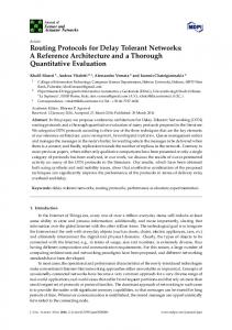
The simulations were done on the ProphetSim simulator [15], whose implementation is based on OMNeT++, version 3.2p1, and uses the Mobility Framework, version 1.0a6. For evaluation purposes, the two scenarios described in Section 4 have been used. In the graphs below, each point represented is the average result of five simulation runs. The same simulation run was used for generating the multicast, multidest and unicast data, so that performance can be compared. The chosen forwarding policies are GRTRsort and MBAF (Multicast Bundles After). Fig. 2 shows the bundle delivery ratio as the ratio between received messages and sent messages. If the message is not delivered to all group members by the end of the simulation, it counts to the delivery ratio with a value equal to the ratio between the number of group members that received the message and the total number of group members. Fig. 3 shows the average delay for bundles to be delivered to their destination. This delay is an average delay for all destinations to which the bundles were successfully delivered within the simulation time. Fig. 4 shows the number of nodes grafted to the multicast tree in a randomly selected starting point (186s) and with a randomly selected period (800s). This number includes the members of the multicast group (source plus 8 destinations) as well as mule nodes that cooperate in the message transmission. b) Scenario 2 Bundle delivery rate
Bundle delivery rate
a) Scenario 1 1 0.9 0.8 0.7 0.6 0.5 0.4 0.3 0.2 0.1 0 60
70
80
90
100 110 120 130 140 150 160
Signal propagation range [meters] Multicast
Unicast
Multidest
1 0.9 0.8 0.7 0.6 0.5 0.4 0.3 0.2 0.1 0 60
70
80
90
100 110 120 130 140 150 160
Signal propagation range [meters] Multicast
Fig. 2. Bundle delivery ratio for: a) Scenario_1; b) Scenario_2
Unicast
Multidest
12
José Santiago, Augusto Casaca and Paulo Rogério Pereira b) Scenario 2 Bundle delay average [s]
Bundle delay average [s]
a) Scenario 1 3000 2500 2000 1500 1000 500 0 60
70
80
90
100
110
120
130
140
150
7000 6000 5000 4000 3000 2000 1000 0
160
60
70
80
Signal propagation range [meters] Multicast
Unicast
90
100
110
120
130
140
150
160
Signal propagation range [meters]
Multidest
Multicast
Unicast
Multidest
Fig. 3. Bundle delay average for: a) Scenario_1; b) Scenario_2 b) Scenario 2
a) Scenario 1
Number of group members
Number of group members
35 30 25 20 15 10 5 0 186
986
1786
2586
3386
4186
35 30 25 20 15 10 5 0 186
986
Simulation Time [s] range90
range100
range110
1786
2586
3386
4186
Simulation Time [s] range160
ranget90
range100
range110
range160
Fig. 4. Number of Multicast group members for: a) Scenario_1; b) Scenario_2
5.1
Wireless Link Range Analysis
The results for unicast and multidest are roughly similar. This is natural, as multidest is based on multiple unicast communications. As the wireless link range increases, the quality of the contacts between nodes and their duration improves so that the delivery rate increases, while the delay average decreases. The exact values depend on the particular scenario characteristics. For multicast, the results shown in Fig. 2 and Fig. 3 must be divided into three parts, according to the wireless link range: 1 From 60m to 100m: here, unicast performs badly and multicast performs worse. This is because contacts are infrequent and their quality is not good. This can be better observed in Fig. 2-a) for wireless ranges below 100 m, where multicast performance quickly drops to a very low value. In these conditions, multicast tree branches and multicast operations have almost no opportunity to work. 2 From 100m to 140m: both unicast and multicast perform well. Multicast presents better results for the bundle delay average. For this wireless link range, the number of contacts and their quality is good for both modes. It must be remembered that, generally speaking, the quality of these contacts are better than in the previous situation. In the simulation conditions, signal propagation is strictly related to link range: the longer this range is, the greater is the duration of contacts between nodes.
Multicast in Delay Tolerant Networks using Probabilities and Mobility Information
13
3 From 140m to 160m: in this case, it could be expected that the increased number of contacts would guarantee good conditions. However, multicast performance declines in scenario 1. In fact, as in the MBAF forwarding policy unicast bundles are offered first than multicast bundles, as the number of unicast bundles is greater than multicast bundles and as the unicast bundles have no limits for replication, the number of unicast bundle copies in the net becomes too large and multicast bundles starve. The quality of communication is, on average, the same as before, but it is not enough for multicast. Now the contact duration is not sufficient and the minimum number of contacting node pairs is not guaranteed for a significant number of mobiles. The large unicast bundle traffic even causes perturbations in the multicast tree. This can be observed in point 2586 s of Fig. 4-a), where the results for range 160 m are worse than for shorter ranges. This suggests that a different forwarding mechanism that better shares the bandwidth between unicast and multicast should be implemented. 5.2
Forwarding Strategies Analysis
Other forwarding strategies were tested. Fig. 5 and Fig. 6 show the delivery ratio and delay average for the LESSD forwarding strategy. With this strategy, the multicast delivery rate improves 0.5% on the average, which can be noted for the wireless range 160 m on Scenario_1, while its average delay decreases about 0.5% for the operating range (100 m and above). However, the cost is a significant degradation for unicast and multidest delivery rates (about 20%) and average delays (about 30%). a) Scenario 1 - GRTRSort/LESSD
b) Scenario 2 - GRTRsort/LESSD Bundle delivery rate
Bundle delivery rate
1 0.9 0.8 0.7 0.6 0.5 0.4 0.3 0.2 0.1 0 60
70
80
90
1 0.9 0.8 0.7 0.6 0.5 0.4 0.3 0.2 0.1 0
100 110 120 130 140 150 160
60
70
Signal propagation range [meters] Multicast
Unicast
80
90
100 110 120 130 140 150 160
Signal propagation range [meters]
Multidest
Multicast
Unicast
Multidest
Fig. 5. Bundle delivery ratio using LESSD for: a) Scenario_1; b) Scenario_2 b) Scenario 2 - GRTRsort/LESSD Bundle delay average [s]
Bundle delay average [s]
a) Scenario 1 - GRTRSort/LESSD 3000 2500 2000 1500 1000 500 0 60
70
80
90
100
110
120
130
140
150
Signal propagation range [meters] Multicast
Unicast
Multidest
160
7000 6000 5000 4000 3000 2000 1000 0 60
70
80
90
100
110
120
130
140
150
Signal propagation range [meters] Multicast
Unicast
Multidest
Fig. 6. Bundle delay average using LESSD for: a) Scenario_1; b) Scenario_2
160
14
José Santiago, Augusto Casaca and Paulo Rogério Pereira
Fig. 7 and Fig. 8 show the delivery ratio and delay average when the epidemic forwarding strategy is used for unicast traffic. By comparing this situation with Fig. 2 and Fig. 3, we can conclude that epidemic routing reduces the delay for unicast traffic, but also reduces its delivery rate for the usual situations. As epidemic maximizes message replication, it also minimizes the time for messages to be delivered to their destination. However, as more messages circulate, and as storage is limited, the delivery rate is reduced since more copies of the same messages circulate. An exception is for low wireless ranges, where the reduced number of contacts between nodes can benefit from epidemic forwarding. Since multicast traffic uses its own forwarding strategy, it is not affected much. Actually, it seems to benefit somewhat from the reduced delivery rate of unicast traffic. Again, an exception is for low wireless ranges in Scenario_2, where the increased success of unicast degrades multicast performance. b) Scenario 2 - Epidemic/MBAF Bundle delivery rate
Bundle delivery rate
a) Scenario 1 - Epidemic/MBAF 1.0 0.9 0.8 0.7 0.6 0.5 0.4 0.3 0.2 0.1 0.0 60
70
80
90
100
110
120
130
140
150
1 0.9 0.8 0.7 0.6 0.5 0.4 0.3 0.2 0.1 0
160
60
70
Signal propagation range [meters] Multicast
Unicast
80
90
100 110 120 130 140 150 160
Signal propagation range [meters]
Multidest
Multicast
Unicast
Multidest
Fig. 7. Bundle delivery ratio using Epidemic for a) Scenario_1; b) Scenario_2 b) Scenario 2 - Epidemic/MBAF Bundle delay average [s]
Bundle delay average [s]
a) Scenario 1 - Epidemic/MBAF 3000 2500 2000 1500 1000 500 0 60
70
80
90
100
110
120
130
140
150
Signal propagation range [meters] Multicast
Unicast
Multidest
160
6000 5000 4000 3000 2000 1000 0 60
70
80
90
100
110
120
130
140
150
160
Signal propagation range [meters] Multicast
Unicast
Multidest
Fig. 8. Bundle delay average using Epidemic for a) Scenario_1; b) Scenario_2
5.3
Load Analysis
Fig. 9 and Fig. 10 show the effect of increasing the number of generated messages to the double both for multidest and multicast. By comparing this situation with Fig. 2 and Fig. 3, we can conclude that the load increase results in a reduced delivery rate for unicast traffic (about 18%), with just minor differences in the delay. Multicast shows only a small increase in the delay (about 5%) for Scenario_2 and minor modifications otherwise.
Multicast in Delay Tolerant Networks using Probabilities and Mobility Information
a) Scenario 1
b) Scenario 2 Bundle delivery rate
Bundle delivery rate
1 0.9 0.8 0.7 0.6 0.5 0.4 0.3 0.2 0.1 0 60
70
80
90
100
110
120
130
140
150
1 0.9 0.8 0.7 0.6 0.5 0.4 0.3 0.2 0.1 0
160
60
70
Signal propagation range [meters] Multicast
15
Unicast
80
90
100 110 120 130 140 150 160
Signal propagation range [meters]
Multidest
Multicast
Unicast
Multidest
Fig. 9. Bundle delivery ratio with load increase for a) Scenario_1; b) Scenario_2 b) Scenario 2 Bundle delay average [s]
Bundle delay average [s]
a) Scenario 1 3000 2500 2000 1500 1000 500 0 60
70
80
90
100
110
120
130
140
150
Signal propagation range [meters] Multicast
Unicast
Multidest
160
7000 6000 5000 4000 3000 2000 1000 0 60
70
80
90
100
110
120
130
140
150
160
Signal propagation range [meters] Multicast
Unicast
Multidest
Fig. 10. Bundle delay average with load increase for a) Scenario_1; b) Scenario_2
5.4
Evaluation
The simulation results confirm that the use of multicast mode in DTNs is advantageous. Moreover, Scenario_2 is positively thought to be more realistic than Scenario_1. It fits better to the human community activity, and it is here that multicast adds better quality of service. After achieving a sufficient number of contacts with quality, the bundle delivery ratio is the best in multicast. The bundle delay average for multicast is even better than for unicast as can be observed in most figures for the operating wireless ranges. This can be explained by the use of mobility information for the multicast routing, while unicast routing just uses contact probability. The mobility information permits the pseudo multicast tree to have more direct connections, optimizing the paths and reducing delay. Fig. 4 illustrates that multicast trees work in DTNs if the needed conditions exist: valuable contacts between nodes, with enough duration and communication possibility. Fig. 4 also shows that the effectiveness of the multicast tree is not proportional to the number of nodes grafted with the tree. Indeed, the multicast mode performs better in Scenario_2, despite the larger number of multicast members in Scenario_1. This happens because another factor affects the results. Indeed, the geographical position that crucial members occupy in the overall network is also important. A paradigmatic example is given by a node positioned in a strategic point, where many nodes pass towards multiple directions. This case represents privileged places where mules load, unload and exchange messages.
16
José Santiago, Augusto Casaca and Paulo Rogério Pereira
6
Conclusion
In DTNs, communication channels may fail repeatedly. They can do that for long periods of time. Considering such conditions, it might not seem realistic to try to use multicast trees to deliver messages in scenarios like these. Nevertheless, to prove that it is indeed possible, we extended DTP-PP with a multicast mode, adding information with indications of node position and direction of movement to help forming pseudo multicast trees. The work presented here proves that the multicast mode can be used if a minimum of contacts between nodes exists. The GRTRsort/MBAF forwarding strategies were those that gave best results. The use of position and direction information proved to be a good routing metric, contributing to the existence of a pseudo-multicast tree, which results in shorter message transfer delays. There are situations in which multicast can even perform better than unicast, as is the case of Scenario_2. This is justified by the use of nodes located in strategic points that can be crucial for the performance of communication. Multicast can improve DTNs efficiency, as it permits saving resources as the number of message replications is minimized in the network. Fewer replications mean that less processing capacities are needed, more memory and bandwidth are available and packets suffer less delay and loss. This adds a valuable contribution to the quality of service in DTNs as it does for other communication systems. Some other further work topics are: testing other heuristics for building the pseudomulticast tree; evaluating the effect of error or lack of knowledge in the location information; determining the best values for the protocol parameters according to the mobility model or automatically.
References 1. V. Cerf et al., “Delay Tolerant Network Architecture”, IETF, RFC 4838, April 2007. 2. K. Scott and S. Burleigh, “Bundle Protocol Specification”, IETF, RFC 5050, November 2007. 3. A. Vahdat and D. Becker, “Epidemic Routing for Partially Connected Ad Hoc Network”, Duke University Technical Report Cs-200006, April 2000. 4. A. Lindgren and A. Doria, “Probabilistic Routing Protocol for Intermittently Connected Networks”, IETF, draft-lindgren-dtnrg-prophet-02.txt, March 2006. 5. S. Symington, R. Durst, “Bundle Protocol Extensions to Support Multicasting”, IETF, draft-irtf-dtnrg-bundle-multicast-00.txt, October 2005. 6. W. Zhao, M. Ammar and E. Zegura, “Multicasting in Delay Tolerant Networks: Semantic Models and Routing Algorithms”, SIGCOMM’05, Philadelphia, USA, August 2005. 7. José Santiago and Augusto Casaca, “Non-Custodial Multicast Operations on Intermittently Connected Networks”, EuroFGI Workshop on IP and Traffic Control, pp.143-150, Lisbon, Portugal, December 2007. 8. Susan Symington, Robert C. Durst, Keith Scott, “Custodial Multicast in Delay Tolerant Networks”, 4th IEEE Consumer Communications and Networking Conference, CCNC’2007, pp.207-211, January 2007.
Multicast in Delay Tolerant Networks using Probabilities and Mobility Information
17
9. José Santiago, Augusto Casaca, Paulo Rogério Pereira, “Non-Custodial Multicast over the DTN-Prophet Protocol”, 2008 IFIP Conference on Wireless Sensor and Actor Networks, Ottawa, Ontario, Canada, Springer-Verlag IFIP series, vol. 264/2008, pp. 197-208, July 2008. 10. S. Symington, R. Durst, K. Scott, “Delay-Tolerant Networking Previous Hop Extensions Header”, IETF, draft-irtf-dtnrg-bundle-previous-hop-extension-header-00, April 2006. 11. A. Lindgren, A. Doria and O. Schelén, “Probabilistic Routing Protocol for Intermittently Connected Networks”, Mobile Computing and Communication, Springer LNCS, Volume 3126, pp. 239-254, January 2004. 12. Philo Juang, Hidekazu Oki, Yong Wang, Margaret Martonosi, LiShiuan Peh and Daniel Rubenstein, “Energy-Efficient Computing for Wildlife Tracking: Design Tradeoffs and Early Experiences with ZebraNet”, ASPLOS-X conference, San Jose, CA, October, 2002. 13. Avri Doria, Maria Uden, Durga Prasad Pandey, “Providing connectivity to the Saami nomadic community”, Development by Design Conference 2002. 14. T. Camp, J. Boleng and V. Davies, “A survey of mobility models for ad hoc network research,” Wireless Communications & Mobile Computing (WCMC): Special issue on Mobile Ad Hoc Networking: Research, Trends and Applications, vol. 2, no. 5, pp. 483-502, 2002. 15. Anders Lindgren Software Releases. http://www.sm.luth.se/~dugdale/index/software.shtml