yCadence Design Systems, Inc., San Jose, CA 95134. Abstract. This paper ... http://www.cs.virginia.edu/~robins/vlsi cad.html. Switch Block. Logic Blocks.
Performance-Oriented Placement and Routing for Field-Programmable Gate Arrays � Michael J. Alexander, James P. Cohoon, Joseph L. Ganleyy, and Gabriel Robins Department of Computer Science, University of Virginia, Charlottesville, VA 22903-2442 y Cadence Design Systems, Inc., San Jose, CA 95134
Abstract
This paper presents a performance-oriented placement and routing tool for eld-programmable gate arrays. Using recursive geometric partitioning for simultaneous placement and global routing, and a graphbased strategy for detailed routing, our tool optimizes source-sink pathlengths, channel width and total wirelength. Our results compare favorably with other FPGA layout tools, as measured by the maximum channel width required to place and route a number of industrial benchmarks.
1 Introduction
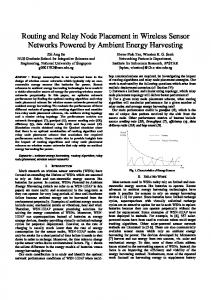
Field-programmable gate arrays, or FPGAs, a�ord designers a versatile and inexpensive way to implement and test VLSI designs [5, 10]. FPGAs are available in a number of styles and con gurations [29]. One of the most common FPGA architectures consists of symmetrical arrays of user-con gurable logic blocks interconnected by a set of programmable routing resources [32] (Figure 1). FPGA reprogrammability is achieved at the expense of performance, i.e., long signal delays through the recon gurable routing resources. This penalty is of primary concern to designers and users alike [28]. To increase FPGA performance, partitioning and technology mapping have been extensively studied [7, 12, 18, 24]. However, the observation that circuit performance is impacted more by routing delays rather than by device delays [4, 17] has focused recent attention on routing [1, 2, 6, 9, 21, 22, 31]. In this paper we present an FPGA Placement and Routing (FPR) tool. FPR is based on a recursive geometric strategy for simultaneous placement and global routing, followed by a graph-based detailed-routing phase. FPR heuristically minimizes both wirelength and source-sink pathlengths. Thus, FPR optimizes the number of FPGAs required to implement a given design, as well as the performance of the implementation. In particular, FPR successfully routes a number of large industrial benchmark circuits using smaller channel widths than other FPGA layout tools. � This work is supported by NSF grants CCR{9224789 and MIP{9107717 (Cohoon), a Virginia SpaceGrant Fellowship (Ganley), and NSF Young Investigator Award MIP{ 9457412 (Robins). Additional related papers may be found at http://www.cs.virginia.edu/~robins/vlsi cad.html
Switch Block
Logic Blocks
Figure 1: Symmetrical-array FPGA.
2 Overview
Placement and routing are performed after the technology-mapping phase of the FPGA design process. Thus, the input to FPR consists of unplaced logic blocks and a set of nets (a net is a set of logic block I/O pins that must be interconnected). FPR performs simultaneous placement and global routing using a recursive geometric technique called thumbnail partitioning, which decomposes the circuit area into an m � n grid, for some small xed m and n. This grid is called the partitioning template. The placement is then optimized and a global routing is determined relative to the partitioning template using optimal rectilinear Steiner arborescences 1 (RSAs) [23]. Since m and n are small and xed, these optimal RSAs (called thumbnails ) may be precomputed for e�cient lookup during execution. Setting m = n = 3 yields the basic 3 � 3 partitioning template that is used in our implementation (Figure 2). Thumbnail partitioning is a generalization of sharp partitioning [3], which in turn is a generalization of quadrisection [27]. The overall strategy consists of a placement and global-routing phase, followed by a detailed-routing phase. During placement and global routing, a partitioning heuristic is used to assign the logic blocks
1 An RSA is a minimum-weight rectilinear tree that contains a shortest path from a designated source vertex to all other vertices/sinks.
Figure 2: (a) Partitioning template for m = n = 3; (b) a sample pointset (the source is at the upper-left); and (c) one of its possible thumbnails. to regions in the partitioning template, minimizing source-sink pathlengths as well as the total length of the thumbnails. When the circuit area is divided according to the partitioning template, each logic block lies in one of the m � n regions. For each net, we construct a pointset in the m � n grid, where a point is present in a region if some logic block associated with the net lies in that region. A thumbnail over this pointset is then determined. To reduce overall routing congestion, alternative thumbnails are selected in order to balance the number of thumbnail edges that cross each edge of the partitioning template. \Virtual" pins are then created at the intersections of thumbnails and partitioningtemplate edges, and the algorithm is then applied recursively to each subregion of the partitioning template. This scheme simultaneously produces both a placement and a global routing in which source-sink pathlengths, total wirelength, and maximum channel congestion are all heuristically minimized. The resulting placement and global routing is then used in the detailed-routing phase to produce a complete routing solution. Detailed routing consists of assigning speci c routing resources from the global routes to each net. By modeling the FPGA routing architecture as a graph, e�cient graph-search algorithms can be used to produce detailed-routing solutions. The nets are routed one at a time. As resources are committed to nets, the corresponding edges in the underlying graph are made unavailable to subsequent nets. The next three sections detail the main phases of FPR, namely: (1) logic-block placement and thumbnail selection for balancing congestion, (2) global routing, and (3) detailed routing.
3 Placement
The placement phase overlays the FPGA with the partitioning template and initially partitions the design logic into the m � n regions. Cut lines of the partitioning template go through switch blocks so that each logic block lies entirely within a single region of the partitioning template. The distribution of logic
blocks among regions of the partitioning template is then improved using simulated annealing [19], where a move consists of swapping two logic blocks that lie in di�erent regions of the partitioning template and the objective is to minimize (1) the sum of the maximum source-sink pathlengths in the thumbnails over the nets, and (2) the total length of the thumbnails for all nets. I/O blocks on the perimeter of the FPGA are not moved during these iterative re nement steps. An important measure of the quality of a placement and global routing is maximum congestion, which in our case is the number of thumbnail edges crossing any given partitioning-template edge. Thus, once logic blocks have been assigned to regions in the partitioning template, a congestion-balancing step is undertaken.
Figure 3: All eight thumbnails for the pointset shown in the 3 � 3 partitioning template (source is at upperleft). Note that a typical pointset can have many thumbnails; for example, Figure 3 illustrates a pointset and its eight thumbnails. The objective of the congestionbalancing step is to assign one of the precomputed thumbnail alternatives to each net in a manner that minimizes the maximum thumbnail congestion. This task is accomplished using the following greedy heuristic:
� Sort the nets in ascending order of the number of distinct thumbnails for each net; and
� For each net on this list, choose the thumbnail that minimizes the maximum congestion induced by all previously processed nets.
This scheme postpones the global routing of nets for which there are more thumbnail choices. This intuitively enables FPR to better compensate for the less avoidable congestion incurred earlier by nets with fewer thumbnail choices.
Logic Block
Switch Blocks
(a)
Logic−Block Node
Switch−Block Nodes
Connection Edges
Figure 4: Global-routing information for a threepin net, showing the associated logic blocks (dark squares), global route (cross-hatched region), and potential Steiner switch block (single gray square).
Channel Edges
(b)
4 Global Routing Thus far in our discussion, FPR has mapped the logic blocks to regions in the partitioning template and each net has been assigned a thumbnail. Next, every edge in each thumbnail must be assigned to a speci c switch block along the crossed cut-line of the partitioning template. Each such switch block is then conceptually added as a new \virtual" pin in the net. The portion of each net within each region of the partitioning template is then passed on to a lower level of the recursion (this is similar to the virtual terminal [3] and terminal propagation [8] techniques). Thus, the global routing computed for a net corresponds to the topology of its thumbnail. The assignment of nets to switch blocks is accomplished in a manner similar to [26]. The number of nets that can be assigned to each switch block is bounded by the number of nets crossing the cut, divided by the number of switch blocks on the cut. This construction induces a complete bipartite graph with nets in one partition and switch blocks in the other. Edge weights in this graph model the cost of assigning a net to the corresponding switch block. Assignments are then determined by computing a minimum-cost matching. The recursion terminates when a region contains at most one logic block (along with the adjacent channel segments, connection blocks, and switch blocks). We then route nets within the channels surrounding the logic block (if it exists) while minimizing the maximum channel congestion. In our implementation, an optimal solution is computed using integer programming. This is e�cient in practice since the number of nets involving any single logic block is small [11].
Switch−Block Edges
Figure 5: Global-routing information (a) is used to construct routing graph (b) for a Xilinx [32] 4000series part with a channel width of 2.
5 Detailed Routing
Following the placement and global-routing phases described above, FPR performs detailed routing by assigning speci c channel and switch-block edges to each net. The placement and global-routing phase passes the following to the detailed router: (1) the locations of relevant logic-block pins (i.e., the net to be routed), (2) a \loose" route for the net (leaving unspeci ed the edges within channel segments and switch blocks), and (3) switch blocks that are likely to serve as Steiner nodes in the detailed routing (Figure 4). A main design goal for FPR is the ability to handle a wide variety of FPGA architectures. To achieve this goal we have adopted a graph-based approach to detailed routing. Each switch block contains internal switch-block edges that may be programmed to connect incoming channel edges. This allows detailed routes to pass through the switch block (Figure 1). Connection edges allow logic-block pins to latch onto adjacent channel edges. The routing structure of the entire FPGA is captured by a routing graph: detailed routes on the FPGA correspond to paths in the routing graph, and vice-versa (Figure 5). In a routing graph, vertices model logic-block and switch-block nodes, while the edges correspond to connection, channel, and switch-block edges. This strategy enables the detailed router to employ generic graph algorithms in order to produce detailed-routing solutions.
Using the routing-graph approach, detailed routing entails interconnecting the logic-block vertices using the edges and vertices inside the corresponding global-route region. This goal is modeled by the graph Steiner tree (GST) problem: given graph G = (V; E), where V is the vertex set and E � V � V is a set of weighted edges, nd a minimum-weight tree in G that spans a subset of the vertices N � V (the logicblock vertices in a net), using switch-block vertices as possible Steiner nodes. Since the GST problem is NP-complete [15], we utilize the heuristic of Kou, Markowsky and Berman [20] (KMB), which approximately solves the GST problem in polynomial time, and is guaranteed to yield solutions with cost less than twice the optimal. While the KMB heuristic always nds a feasible detailed routing if one exists, it often does not \branch" at the appropriate Steiner nodes (Figure 6(a)). This potential drawback is e�ectively ameliorated using the greedy strategy described below. Our detailed-routing algorithm is based on combining a greedy, iterated heuristic [13, 16] with the KMB algorithm; we refer to this hybrid method as the Iterated-KMB (IKMB) algorithm [1]. Given a routing graph G = (V; E), a net N � V , and a set S of potential Steiner nodes, we de ne the savings of S with respect to N as �KMBG(N; S) = KMBG (N) ? KMBG (N [ S). Intuitively, �KMBG(N; S) represents the interconnect savings incurred by KMB when Steiner nodes in S are included into the node set N to be spanned. This is illustrated in Figure 6(b), where using a candidate Steiner node from the shaded switch block results in an optimal solution. In order to e�ciently nd such Steiner nodes, a set of candidate Steiner nodes is determined for each net. Candidate Steiner nodes are switch-block nodes that correspond to Steiner switch blocks (Figure 4).
(a)
Given these de nitions, the IKMB method operates by repeatedly nding candidate Steiner nodes that reduce the overall KMB cost by the largest amount, and then including them into a growing set S of Steiner nodes. The cost of the KMB tree over N [ S decreases with each added node, and the construction terminates when there is no x 2 V with �KMB(N [ S; fxg) > 0. The nal topology is obtained by computing the KMB construction using N [ S as the pins and the remaining V ? (N [ S) nodes as potential Steiner nodes. The placement and global-routing phases seek to minimize congestion, thereby enabling the detailed router to nd a feasible (and high-quality) solution more easily. However, since it is NP-complete to determine whether there exists a feasible detailed-routing solution for all nets [30], we use a deterministic netordering scheme to route the nets one at a time. When a detailed-routing solution for a net is found, the corresponding routing resources are committed to that net and are made unavailable for subsequent nets (i.e., they are removed from the underlying graph). If infeasibility is encountered during the detailed routing of a net (i.e., some logic-block pin is unreachable in the routing graph from the other pins of the net), the following two heuristics are employed. We rst use an incremental \wavefront-expansion" technique to gradually \loosen" the global route, allowing the detailed route to detour around local blockages caused by previously-routed nets (Figure 7). Note that this wavefront-expansion technique determines the region searched by the routing algorithm, as opposed to the order in which graph edges are explored [14]. We found that in practice, the vast majority of those nets that fail to route using the initial global route become routable after only a single loosening operation. In cases where wavefront expansion fails to produce a routing solution, we next employ a \move-to-front" heuristic [25], where unroutable nets are moved to the beginning of the net-routing order and the new routing order is attempted.
(b)
Figure 6: Detailed-routing solutions; (a) a KMB solu-
tion containing unnecessary parallel paths, while (b) the IKMB solution reduces total number of channel edges by 22%.
Figure 7: Wavefront expansion is used to \loosen" global routes when infeasibility is encountered.
6 Experimental Results
We have implemented our algorithms and incorporated them into FPR. Two FPGA architectures, corresponding to Xilinx 3000-series and 4000-series parts, were modeled [5, 32]; these architectures are identical to the ones used by CGE [6], SEGA [22] and GBP [31], respectively. We compared the performance of these tools on fourteen large benchmark circuits: the suite of ve 3000-series benchmarks used by [6], and the suite of nine 4000-series benchmarks used by [22] and [31]. The 3000-series benchmarks were routed on FPGAs with switch-block exibility Fs = 6 and connection
exibility Fc = d0:6 � W e, where W is the the channel width. The 4000-series benchmarks use FPGAs with Fs = 3 and Fc = W. Name busc dma bnre dfsm z03
Name 9symml term1 apex7 alu2 too large example2 vda alu4 k2
3000-Series Benchmarks Size Nets CGE 13 � 12 151 10 18 � 16 213 10 22 � 21 352 12 23 � 22 420 10 27 � 26 608 13 Totals 55
FPR 9 9 11 11 13 53
4000-Series Benchmarks Size Nets SEGA GBP 11 � 10 79 10 9 10 � 9 88 10 10 12 � 10 115 13 11 15 � 13 153 11 11 14 � 14 186 12 12 14 � 12 205 17 13 17 � 16 225 13 13 19 � 17 255 15 14 22 � 20 404 17 17 Totals 118 110
FPR
9 8 9 10 11 13 13 13 17 103
Table 1: Maximum channel width achieved by FPR on the benchmark circuits.
A common objective in FPGA physical design is to minimize maximum channel width. Table 1 shows the maximum channel widths of actual complete placement and routing solutions produced by FPR; these compare favorably with CGE [6] for the 3000-series benchmarks, and with SEGA [22] and GBP [31] for the 4000-series benchmarks. The channel width required by FPR is smaller than that required by CGE, SEGA, and GBP in 8 of the 14 benchmark circuits, and is equal on all but one of the remaining 6 benchmark circuits. We also measured how well FPR optimizes total wirelength and maximum source-sink pathlengths (i.e., radius ). Since previous works do not report these statistics, we have implemented a modi ed version of FPR, called SFPR, that uses unrooted Steiner trees as thumbnails [11], instead of the preferred arborescence thumbnails described in Section 3. We compared the solutions produced by SFPR against performanceoriented solutions produced by the unmodi ed FPR
tool. These results are summarized in Table 2, where we observe that a 1:0% increase in wirelength has yielded a 6:7% decrease in radius. The time to run FPR is comparable to other tools: CPU times to completely route the circuits on a Sun SparcServer 10/514 workstation ranged from several minutes for the smallest circuit to several hours for the largest. Name busc dma bnre dfsm z03 Average
3000-Series Benchmarks Avg. Wirelength Avg. Max Radius SFPR FPR �% SFPR FPR �% 9.3 9.1 -2.2 6.6 6.0 -9.1 13.2 13.0 -1.5 8.6 7.7 -10.5 14.0 14.0 0.0 9.0 7.9 -12.2 12.0 12.7 5.8 7.3 7.1 -2.7 13.7 14.1 2.9 8.9 8.7 -2.2 12.4 12.6 1.0 8.1 7.5 -7.3
4000-Series Benchmarks Avg. Wirelength Avg. Max Radius Name SFPR FPR �% SFPR FPR �% 9symml 11.4 10.9 -4.4 7.1 6.1 -14.1 term1 7.0 7.4 5.7 5.2 5.2 0.0 apex7 9.1 9.5 4.4 6.3 6.7 6.3 alu2 12.2 12.5 2.5 7.5 7.2 -4.0 too large 11.9 11.5 -3.4 8.5 7.2 -15.3 example2 9.3 9.4 1.1 7.2 6.8 -5.6 vda 15.0 15.0 0.0 10.6 9.4 -11.3 alu4 14.5 14.9 2.8 9.5 9.0 -5.3 k2 17.7 17.7 0.0 13.1 12.1 -7.6 Average 12.0 12.1 1.0 8.3 7.7 -6.3 Overall
12.2 12.3
1.0
8.2
7.6
-6.7
Table 2: Comparison of arborescence-based FPR against Steiner-tree-based SFPR. The �% column gives the percent change from SFPR to FPR.
7 Conclusion
We have developed FPR, a placement and routing tool for FPGAs that combines a recursive geometric strategy for simultaneous placement and global routing with a general graph-based detailed-routing algorithm. FPR addresses performance issues by minimizing source-sink pathlengths as well as total wirelength and maximumchannel width. FPR compares favorably to existing tools on both 3000-series and 4000-series Xilinx-type parts, as measured by the maximumchannel width required for the complete placement and routing of a number of industrial benchmarks.
Acknowledgements
We thank Matt Saltzman for the use of his matching code, and Steve Brown and Jonathan Rose for supplying the benchmark circuits. We are grateful to Dr. Bob Grafton of the National Science Foundation for his support and advice.
References
[1] M. J. Alexander, J. P. Cohoon, J. L. Ganley, and G. Robins, An Architecture-Independent Approach to FPGA Routing Based on Multi-Weighted Graphs, in Proc. European Design Automation Conf., Grenoble, France, September 1994, pp. 259{264. [2] M. J. Alexander and G. Robins, New PerformanceDriven FPGA Routing Algorithms, in Proc. ACM/IEEE Design Automation Conf., San Francisco, CA, June 1995, pp. 562{567. [3] S. Bapat and J. P. Cohoon, A Parallel VLSI Circuit Layout Methodology, in Proc. IEEE Intl. Conf. VLSI Design, January 1993, pp. 236{241. [4] N. B. Bhat and D. D. Hill, Routable Technology Mapping for LUT FPGAs, in Proc. IEEE Intl. Conf. ComputerAided Design, 1992, pp. 95{98. [5] S. D. Brown, R. J. Francis, J. Rose, and Z. G. Vranesic, Field-Programmable Gate Arrays, Kluwer Academic Publishers, Boston, MA, 1992. [6] S. D. Brown, J. Rose, and Z. G. Vranesic, A Detailed Router for Field-Programmable Gate Arrays, IEEE Trans. Computer-Aided Design, 11 (1992), pp. 620{628. [7] K. C. Chen, J. Cong, Y. Ding, A. B. Kahng, and P. Trajmar, DAG-Map: Graph-Based FPGA Technology Mapping for Delay Optimization, IEEE Design & Test of Computers, 9 (1992), pp. 7{20. [8] A. E. Dunlop and B. W. Kernighan, A Procedure for Placement of Standard-Cell VLSI Circuits, IEEE Trans. Computer-Aided Design, 4 (1985), pp. 92{98. [9] J. Frankle, Iterative and Adaptive Slack Allocation for Performance-driven Layout and FPGA Routing, in Proc. ACM/IEEE Design Automation Conf., 1992, pp. 536{542.
[10] A. E. Gamal, J. Greene, J. Reyneri, E. Rogoyski, K. El-Ayat, and A. Mohsen, An Architecture for Electrically Con gurable Gate Arrays, IEEE J. Solid State Circuits, 24 (1989), pp. 394{398. [11] J. L. Ganley, Geometric Interconnection and Placement Algorithms, PhD thesis, Department of Computer Science, University of Virginia, Charlottesville, Virginia, 1995. [12] T. Gao, K. C. Chen, J. Cong, Y. Ding, and C. L. Liu, Placement and Placement Driven Technology Mapping for FPGA Synthesis, in Proc. IEEE Intl. ASIC Conf., Rochester, NY, September 1993, pp. 87{91. [13] J. Griffith, G. Robins, J. S. Salowe, and T. Zhang, Closing the Gap: Near-Optimal Steiner Trees in Polynomial Time, IEEE Trans. Computer-Aided Design, 13 (1994), pp. 1351{1365. [14] W. Heyns, W. Sansen, and H. Beke, A Line-Expansion Algorithm for the General Routing Problem with a Guaranteed Solution, in Proc. ACM/IEEE Design Automation Conf., Minneapolis, 1980, pp. 243{249. [15] F. K. Hwang, D. S. Richards, and P. Winter, The Steiner Tree Problem, North-Holland, 1992.
[16] A. B. Kahng and G. Robins, A New Class of Iterative Steiner Tree Heuristics With Good Performance, IEEE Trans. Computer-Aided Design, 11 (1992), pp. 893{902. [17] A. B. Kahng and G. Robins, On Optimal Interconnections for VLSI, Kluwer Academic Publishers, Boston, MA, 1995. [18] K. Karplus, Xmap: a Technology Mapper for Tablelookup Field-Programmable Gate Arrays, in Proc. ACM/IEEE Design Automation Conf., 1991, pp. 240{243. [19] S. Kirkpatrick, C. D. Gelatt, and M. P. Vecchi, Optimization by Simulated Annealing: An Experimental Evaluation (part 1), Science, 220 (1983), pp. 671{680. [20] L. Kou, G. Markowsky, and L. Berman, A Fast Algorithm for Steiner Trees, Acta Informatica, 15 (1981), pp. 141{145. [21] Y.-S. Lee and A. C.-H. Wu, A Performance and Routability Driven Router for FPGAs Considering Path Delays, in Proc. ACM/IEEE Design Automation Conf., San Francisco, CA, June 1995, pp. 557{561. [22] G. G. Lemieux and S. D. Brown, A Detailed Routing Algorithm for Allocating Wire Segments in FieldProgrammable Gate Arrays, in Proc. ACM/SIGDA Physical Design Workshop, Lake Arrowhead, CA, April 1993. [23] S. K. Rao, P. Sadayappan, F. K. Hwang, and P. W. Shor, The Rectilinear Steiner Arborescence Problem, Algorithmica, (1992), pp. 277{288. [24] K. Roy, B. Guan, and C. Sechen, FPGA MCM Partitioning and Placement, in Proc. ACM/SIGDA Physical Design Workshop, Lake Arrowhead, CA, April 1993, pp. 211{212. [25] H. Shin and A. Sangiovanni-Vincentelli, A Detailed Router Based on Incremental Routing Modi cations: Mighty, IEEE Trans. Computer-Aided Design, 6 (1987), pp. 942{955. [26] H. Spruth, F. Johannes, and K. Antreich, PHIroute: A Parallel Hierarchical Sea-of-Gates Router, in Proc. IEEE Intl. Symp. Circuits and Systems, 1994, pp. 487{490. [27] P. R. Suaris and G. Kedem, A Quadrisection-Based Place and Route Scheme for Standard Cells, IEEE Trans. Computer-Aided Design, 8 (1989), pp. 234{244. [28] S. Trimberger, E�ects of FPGA Architecture on FPGA Routing, in Proc. ACM/IEEE Design Automation Conf., San Francisco, CA, June 1995, pp. 574{578. [29] S. M. Trimberger, Field-Programmable Gate Array Technology, S. M. Trimberger, editor, Kluwer Academic Publishers, Boston, MA, 1994. [30] Y.-L. Wu and M. Marek-Sadowska, Graph Based Analysis of FPGA Routing, in Proc. European Design and Test Conf., 1993, pp. 104{109. [31] Y.-L. Wu and M. Marek-Sadowska, An E�cient Router for 2-D Field Programmable Gate Arrays, in European Design and Test Conf., 1994, pp. 412{416. [32] Xilinx, The Programmable Gate Array Data Book, Xilinx, Inc., San Jose, California, 1994.