IEEE TRANSACTIONS ON NEURAL SYSTEMS AND REHABILITATION ENGINEERING, VOL. 20, NO. 5, SEPTEMBER 2012
617
The Effect of Coil Type and Navigation on the Reliability of Transcranial Magnetic Stimulation Melanie K. Fleming, Isaac O. Sorinola, Di J. Newham, Sarah F. Roberts-Lewis, and Jeroen H. M. Bergmann
Abstract—The objective of this study was to investigate reliability of transcranial magnetic stimulation (TMS) parameters for three coil systems; hand-held circular and figure-of-eight and navigated figure-of-eight coils. Stimulus response curves, intracortical inhibition (SICI) and facilitation (ICF) were studied in the right first dorsal interosseus muscle of 10 healthy adults. Each coil system was tested twice per subject. Navigation was conducted by a custom built system. Cortical excitability showed moderate-to-good reliability for the hand-held and navigated figure-of-eight coils (Intraclass correlation coefficients (ICCs) 0.55–0.89). The circular coil showed poor reliability for motor evoked potential (MEP) amplitude at 120% resting motor threshold and MEP sum (ICCs 0.09 & 0.48). Reliability for SICI was good for all coil systems when an outlier was removed (ICCs 0.87–0.93), but poor for ICF (ICCs < 0.3). The circular coil had a higher than the navigated figure-of-eight coil (p = 0.004). Figure-of-eight coils can be used confidently to investigate cortical excitability over time. ICF should be interpreted with caution. The navigation device frees the experimenter and enables tracking of the position of the coil and subject. The results help guide the choice of coil system for longitudinal measurements of motor cortex function. Index Terms—Coil type, navigation, reliability, three-dimensional (3D) tracking, transcranial magnetic stimulation.
I. INTRODUCTION
T
RANSCRANIAL magnetic stimulation (TMS) is a widely used noninvasive technique for assessing neural mechanisms underlying motor control and recovery from neurological dysfunction. Temporal stability of measurements is important since parameters such as resting motor threshold (RMT), motor evoked potential (MEP) amplitude, short latency intracortical inhibition (SICI), and facilitation (ICF) are often assessed at multiple time-points and also to compare different populations. There are two coil types predominantly used for stimulation of hand muscle representations; the circular and figure-of-eight Manuscript received September 02, 2011; revised March 05, 2012; accepted May 19, 2012. Date of publication June 08, 2012; date of current version September 07, 2012. This work was supported in part by The Dunhill Medical Trust. M. K. Fleming, D. J. Newham, and S. F. Roberts-Lewis are with the Centre of Human and Aerospace Physiological Sciences, School of Biomedical Sciences, King’s College London, London, United Kingdom (e-mail:
[email protected]). I. O. Sorinola is with the Division of Health and Social Care Research, School of Medicine, King’s College London, London, U.K.. J. H. M. Bergmann is with Medical Engineering Solutions in Osteoarthritis Centre of Excellence, Imperial College London, London, U.K.. Color versions of one or more of the figures in this paper are available online at http://ieeexplore.ieee.org. Digital Object Identifier 10.1109/TNSRE.2012.2202692
coils. The centre of the circular coil is placed on or close to the vertex with the edge of the coil close to the hand area of the primary motor cortex (M1). If the left hemisphere is the area of interest then this is preferentially stimulated when the coil current flows in an anticlockwise direction (viewed from above), but there will still be activation of the right hemisphere [1]. The figure-of-eight coil provides a more focal and directed stimulus under the central segment, which is positioned over the hand area of M1. Precise and consistent placement of the figure-ofeight coil is crucial, as both the position and orientation affect the evoked response [2]. Navigation systems enable the position of the figure-of-eight coil to be tracked in real time, ensuring consistency of coil placement [3]. Most navigators work in cooperation with magnetic resonance imaging (MRI) to identify target areas and guide positioning of the TMS coil relative to anatomical or functional landmarks [4], [5]. However, such systems can be expensive and there is an interest in systems that provide feedback on placement, recall previous used positions and allow for comparison over multiple trials without the use of MRI. We have devised a low cost, easy to use navigation system to fix the figure-of-eight coil in place and monitor movements of the coil or subject throughout the session. We hypothesize that the navigation system will allow real-time monitoring of coil and subject positions, allowing any deviations in placement to be corrected and improving reliability of the figure-of-eight coil. Since the figure-of-eight coil provides a more focal stimulation than the circular coil, the reliability of these two coil types may differ. Studies investigating the reliability of the hand-held figure-of-eight coil have shown RMT, MEP amplitude and the slope of the stimulus-response (SR) curve to be consistent over time [6], [7]. Badawy et al. [8] found no significant differences in RMT between the hand-held figure-of-eight and circular coils, but the focus of their study was on paired-pulse measures and therefore differences in the reliability of SR curve and MEP amplitude parameters between the two coil types were not investigated. Malcolm et al. [9] reported good SR curve repeatability for abductor pollicis brevis and first dorsal interosseus (FDI) with the circular coil, but made no direct comparison with the figure-of-eight coil. Information regarding the differences between coil types would be useful in helping guide the coil selection for a specific study. Paired pulse TMS is commonly used to investigate changes in SICI or ICF [10]. Previous studies have found the variability of SICI and ICF with a figure-of-eight coil to be high between subjects and sessions [11], [12], although increasing the number of MEPs recorded does reduce intersession variability [11]. Comparisons between the hand-held figure-of-eight and circular coils have reported similar amounts of inhibition
1534-4320/$31.00 © 2012 IEEE
618
IEEE TRANSACTIONS ON NEURAL SYSTEMS AND REHABILITATION ENGINEERING, VOL. 20, NO. 5, SEPTEMBER 2012
and facilitation for the two coil types at various interstimulus intervals [8], [13]. One study has compared the reproducibility of paired pulse measures for the hand-held figure-of-eight and circular coils [8] and found no significant session-to-session differences in SICI or ICF with either coil. However, they did not use intraclass correlation coefficients (ICCs) or Bland and Altman analyses [14] to evaluate the strength of agreement between sessions, although these are suggested to be the most appropriate statistical methods for reliability studies [15], [16]. A repeated measures analysis of variance (rmANOVA) may show no significant differences, but does not provide any assessment of whether pairs of data are in agreement. ICCs reflect the degree of correspondence and agreement between pairs of measurements [16] and Bland and Altman analyses provide a visual representation of the agreement between measures, allowing patterns in the spread of differences to be realized [14], [16]. Therefore, intersession reliability for SICI and ICF requires further investigation. Within session variability of MEP amplitudes is known to be high, particularly at lower stimulation intensities, and the maximum MEP amplitude from a block of responses is likely to deviate substantially from the true mean [17]. Removal of MEP outliers may introduce bias if determined subjectively by the experimenter and therefore a systematic method for trimming of MEP outliers will be investigated. We hypothesize that systematically trimming MEP outliers will result in reduced within session variability. There were three aims of this study, 1) to examine reliability of the hand-held circular coil and the figure-of-eight coil with and without navigation by investigating the SR curve and paired pulse parameters across two sessions, 2) to determine whether there are differences in TMS measures between the three coil systems, and 3) to determine the effect of trimming MEP outliers on within session variability and TMS measures. II. METHODS A. Participants Ten healthy adults (mean age 33, range 26–61 years, three females, one left handed) each participated in three sessions. All participants provided written informed consent and the study was approved by the local ethics committee. All sessions were performed at the same time of day and were on average seven days apart (range 3–14 days). Some of the participants had experienced TMS previously, but all were experiencing the navigation system for the first time. Three experimenters tested the participants. Two were relatively novice to TMS, and tested one participant each (completing all three sessions), and the remaining participants were tested by an experienced TMS user. The experienced TMS user was present for every session with the novice experimenters to offer guidance as required. All experimenters were familiarized with the navigation system before testing any participants. B. Experimental Setup Participants were seated comfortably in a reclined dental chair, with their hands relaxed on a pillow on their lap. Surface
electomyography (EMG) was recorded bilaterally from the first dorsal interosseus (FDI) using pairs of 13 mm Ag/AgCl Biotab electrodes (Unomedical, Worcestershire, U.K.) placed over the muscle in a belly-tendon montage, following standard skin preparation techniques. A common ground electrode was placed over the right ulnar styloid (23 mm Ag/AgCl Biotab electrode). The analog EMG data were pre-amplified 1000 (Digitimer Ltd, Hertfordshire, U.K.) and bandpass filtered at 30–1000 Hz (Neurolog filter module, Digitimer, Hertfordshire, U.K.) with a 50 Hz notch filter. Data was acquired at 2 kHz, A to D converted (1401, Cambridge Electronic Design Ltd (CED), Cambridge, U.K.), recorded (Signal 4.07, CED, Cambridge, U.K.) and stored for offline analysis. C. Transcranial Magnetic Stimulation (TMS) Setup TMS was delivered by a pair of Magstim 200 magnetic stimulators connected through a BiStim module (Magstim,Carmarthenshire, U.K.). TMS parameters were measured for the right FDI only. Three coil systems were used; hand-held circular and figure-of-eight and navigation assisted figure-of-eight coil. The circular coil was 90 mm in diameter and the figure-of-eight coil outer wing diameter was 70 mm (Magstim, Carmarthenshire, U.K.). Two systems were tested in each of the three sessions, so that each system was tested twice, in a pseudo-randomised order. Circular Coil: The vertex of the participant’s head was determined with a tape measure by using half the distance from nasion to inion, and half the distance from the left to the right tragus. This position was marked on the participants scalp. The coil was held with side “A” facing upwards, to preferentially stimulate the left hemisphere. The hotspot was determined using a stimulation intensity just above RMT. The coil was placed initially on the vertex, and then moved in cm squares to determine the optimal position for eliciting MEPs from the right FDI (hotspot). This position was marked with a water-soluble pen directly on the scalp to ensure consistent coil placement within the session. Hand-held Figure-of-eight Coil: The coil was placed on the scalp over the left motor cortex. It was held tangential to the scalp at approximately 45 to the midline, such that the current flow in the cortex was in a posterior–anterior direction and approximately perpendicular to the central sulcus. The hotspot was determined by moving the coil in cm squares and marked in the same manner as for the circular coil. Navigation System Used for the Figure-of-Eight Coil (Fig. 1): Three spatial tracking systems (MadCatz Gametrack, Mad Catz Inc., San Diego, CA) were mounted on the ceiling over the head end of the dental chair (Fig. 1). Each unit uses a spring-tensioned nylon tether connected to a rotary potentiometer to measure the distance that the tether is moved [18]. This mechanism produces a constant pull of the tether, which ensures a quick response to changes in distance and prevents slack of the tether. The pull for each tether was measured to be 1.26 newtons and a distance of 2.72 m could be travelled. Each tether passes through a small tubular guide arm. This guide arm is part of a low resistance ball joint that allows the cable to be moved freely over a conical space that covers a vertex angle of 70 . The vertex angle is defined as the angle of the cross section within the plane of the
FLEMING et al.: THE EFFECT OF COIL TYPE AND NAVIGATION ON THE RELIABILITY OF TRANSCRANIAL MAGNETIC STIMULATION
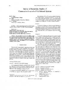
Fig. 1. Experimental setup for navigated figure-of-eight coil (1.1) and a schematic representation of the setup (1.2). A: Coil. B: Custom built arm. C: Spatial tracking system.
Fig. 2. The global (X, Y, Z) and local (y, x, z) coordinate frames used. Each tether had a local coordinate frame that was referenced to the overall coordinate frame. The two long approximately vertical lines are the tethers.
apex and centre of the base covering the conical space. The ball joint mechanism is similar to those found in analog joysticks. The angle at which the tether is pulled is sensed by a bi-axial potentiometer. Two tethers were housed within each unit. From the distance and angle data, a three-dimensional (3D) position of the tether’s endpoint was calculated. The local Polar coordinate system was transformed to a local Cartesian coordinate system. The endpoints were then transformed to the global Cartesian coordinate frame by applying a translation matrix. The translation matrix for each tether was based on the location of the origin of each unit within the global reference frame. The distances were measured between the origin of the unit and the selected origin of the global frame (Fig. 2). Each tether has a plastic female connector at the end of it, which fits to a matching male connector. These connectors made it easier to attach and unattach the wires from the objects being tracked. The control electronics used serial protocols for USB employing the Human Interaction Device (HID) protocols for personal computers [18]. Six tethers were used to obtain accurate information regarding the position of the head and the coil in a global
619
reference frame (Fig. 1). Accuracy of the navigation system was determined by comparison to an optical tracker system (Codamotion, Charnwood Dynamics, Leicestershire, U.K.). An active optical marker was placed on the female connector (endpoint). The male connector was attached on a metal frame that was placed within the calibrated space of the optical tracking system. The frame provided a rigid basis that minimized displacement of the endpoint once it was connected. The tethered spatial tracking system itself was placed at the base of the metal frame and firmly secured. In total 20 lengths were measured ranging from 290 to 950 mm and covering the full vertex angle of 70 . It was found that the initial length increase (< 250 mm) was not linear and it was therefore not taken into account. This loss of linearity at the start of lengthening would not influence the readings taken during TMS navigation as the length of tethers exceed the value at which nonlinearity occurred. All data obtained from the tethered unit was transformed to the Cartesian coordinate system of the optical tracking system. An additional optical marker placed on the origin of the base unit provided the information to transform between the local and global systems. The changes in position covered a conic volume that was greater than required for TMS navigation. Position data were collected covering the conic volume that would be used during TMS navigation. A root mean square error of 2 mm was found for all three dimensions. To determine head position the participant wore a pair of glasses with three male connection points (between the eyes, right side and left side of the head) for the tethers. Additional weights were placed on the side of the glasses to counteract the previously mentioned pull of the tethers. The location of the coil in 3D space was obtained by connecting the outer edge of each wing and the handle of the coil to the tethers of the tracking system. Position data were recorded via USB on a laptop using a customized Matlab programme (The Mathworks Inc., Natick, MA) that controlled a programmable input emulator (GlovePie, 0.43, Carl Kenner). Position data were displayed for each of the spatial trackers. Previous recorded positions could be viewed alongside the real-time data. The difference between a previous selected placement and the current one was fed back to the user. This information allows the user to correct for displacements within TMS sessions and minimize the differences over multiple sessions. The coil was held by a quick-release system that was fixed to a universal locking joint (6 degrees-of-freedom SLIK pan head, Kayama, Japan) that could be adjusted in all three planes. The quick-release system composed of a tight fitting mold that consisted of two parts that were kept together by velcro-straps. This mechanism provided the means to quickly attach and detach the coil from the joint locking system. The joint itself was connected to an arm that was adapted from a dentist’s ceiling mounted lamp. This setup allowed free movement of the coil, while maintaining its position once correctly placed on the participant’s scalp (Fig. 1). The hotspot was initially determined when holding the coil by hand, and then confirmed with the navigation device in place. Position of the head and coil was displayed on a computer screen throughout data collection, updated every 0.4 s. The initial position of each marker was also displayed on the screen, allowing
620
IEEE TRANSACTIONS ON NEURAL SYSTEMS AND REHABILITATION ENGINEERING, VOL. 20, NO. 5, SEPTEMBER 2012
the TMS user to correct for any deviation from the original position throughout the whole protocol. The participants were encouraged to remain as still as possible throughout testing and the 3D positions were checked regularly by the experimenter to determine if displacement of the head or coil had occurred. D. TMS Parameters The same measures were collected for each coil system. Resting motor threshold (RMT) was determined for the right FDI as the lowest intensity to give a motor evoked potential (MEP) V in at least 5 out of 10 consecutive stimuli. A stimulus-response (SR) curve was constructed by delivering 10 stimuli at five different intensities (90%, 100%, 110%, 120%, and 130% RMT) in a pseudo-randomised order. Paired-pulse TMS was delivered to evaluate short latency intracortical inhibition (SICI) and intracortical facilitation (ICF). The test stimulus was at the intensity which produced an MEP of approximately 50% of the participants maximum achievable MEP, such that the intensity would lie on the steep portion of the SR curve, allowing both increases and decreases in MEP amplitude to be observed. This intensity was determined following hotspot localization, prior to collecting SR curve data. Stimuli were delivered in increments of approximately 5%–10% maximum stimulator output (MSO) and peak-to-peak MEP amplitude measured online in order to determine the maximum MEP achievable (up to 100% MSO if needed). The conditioning stimulus was set to 85% RMT, and interstimulus intervals (ISI) of 2.5 and 12.5 ms used for SICI and ICF respectively (conditioning stimulus preceding test stimulus). Ten nonconditioned responses were recorded and 10 conditioned responses at each ISI, in a pseudo-randomized order. E. Data Analysis Three dimensional marker data were continuously recorded throughout the use of the navigation system. Changes in marker positions within the sessions were determined by calculating the root mean square (rms) for each participant and condition. The average and range of rms was then computed for each of the sessions, as a measure of movement that occurred during the navigated trials. Peak-to-peak MEP amplitude (mV) was determined for each of the 10 MEPs from the right FDI for each block of the SR curve and each paired-pulse block using Signal 4.07 (CED, Cambridge, U.K.). Pre-trigger rms EMG was determined for bilateral FDI over a 50 ms period ending 5 ms before the stimulus. Trimming was performed in order to remove outliers: the 10 MEPs at each stimulation intensity were ranked by amplitude and then the highest and lowest responses removed before averaging [19]. Only untrimmed data were used for the reliability analysis and both trimmed and untrimmed data were analyzed for the comparison of TMS measures between coil systems. The average MEP amplitude at each of the five stimulus intensities of the SR curve was calculated, and added together to determine the MEP sum, with a higher value indicating greater output for the same input. In addition, the MEP amplitude at
was recorded to examine reliability at a 120% RMT single intensity of stimulation. Within session MEP variability was assessed using the coefficient of variation (CV), calculated for the SR curve and for SICI and ICF by dividing the standard deviation of each block of MEP amplitudes with the average MEP amplitude from that block. For the SR curve, the CV of each block was averaged to determine the overall CV. For the paired pulse TMS, the average MEP amplitude for SICI and ICF were expressed as a percentage of the non-conditioned response (% NC). Values < 100% indicate inhibition and those > 100% indicate facilitation of the test response. F. Statistics Reliability: Intersession reliability was assessed using ICCs and Bland and Altman analyses [14]. ICCs were determined using SPSS 17.0 (SPSS Inc., Chicago, IL) with a type C (two way mixed effects model) average measure algorithm, based on the Shrout and Fleiss ICC (3, k) equation [20]. Bland and Altman plots were constructed to examine the difference between sessions against the average of the two sessions. The 95% limits of agreement were calculated using GraphPad Prism 5.0 (GraphPad Software, San Diego, CA). The coefficient of repeatability (CR) was calculated using the equation
where is the difference between sessions and is the number of participants [12]. Comparison of TMS Measures Between Coil Systems: A repeated measures analysis of variance (rmANOVA) was used to test for differences between coil systems and for the effect of trimming (SPSS 17.0, SPSS Inc., Chicago, IL). For RMT a 3 COIL SYSTEM by 2 SESSION rmANOVA was used. For all other TMS parameters a 2 TRIMMING by 3 COIL SYSTEM by 2 SESSION rmANOVA was used. Level of significance was set at < 0.05. Greenhouse–Geisser corrections were applied as necessary to correct for violations in the sphericity assumption highlighted by Mauchly’s test of sphericity. To further investigate main effects, post-hoc analyses were completed using two tailed paired t-tests and a modified Bonferroni correction [21]. III. RESULTS A. Navigation System Data Position data for each of the six tethers were recorded in three planes (x, y, z) during collection of the SR curve and paired pulse blocks for each session. The rms ranged from 0.03-6.1 mm (average 0.5 mm) for session one and 0.02-5.9 mm (average 0.8 mm) for session two. B. Pretrigger RMS EMG The lack of EMG activity before TMS indicated relaxation in all trials. There was no effect of coil system, session or TMS parameter on rms values for either right or left FDI.
FLEMING et al.: THE EFFECT OF COIL TYPE AND NAVIGATION ON THE RELIABILITY OF TRANSCRANIAL MAGNETIC STIMULATION
621
Fig. 3. Bland and Altman plots contrasting difference between sessions with the average across sessions for RMT (left panel) and MEP amplitude at 120% RMT (right panel). Solid line = mean difference. Dotted lines = upper and lower 95% limits of agreement. CR = coefficient of repeatability. ICC = intraclass correlation coefficient. Black circles indicate outliers. A and D: Hand-held figure-of-eight coil. B and E: Circular coil. C and F: Navigated figure-of-eight coil.
C. Reliability Analysis The results of the Bland and Altman analyses and the ICCs for intersession reliability are presented in Figs. 3 and 4. ICC values above 0.75 are indicative of good reliability and those below show moderate to poor reliability [16]. For the purpose of this study, ICCs between 0.5–0.75 are identified as moderate reliability. The ICC values obtained indicate moderate to good reliability for RMT across all coil systems [Fig. 3(A)–(C)]. reliability was moderate to good using both the hand-held and navigated figure-of-eight coils [Fig. 3(D) and (F)], but poor for the circular coil [Fig. 3(E)]. For all coil systems, the ICC was improved by using MEP sum instead of (MEP sum ICC: figure-of-eight , circle , navigated figure-of-eight ). ICC values for SICI were moderate for the circular coil and good for the navigated figure-of-eight coil [Fig. 4(B) and (C)], but poor for the hand held figure-of-eight coil [Fig. 4(A)] and across all coil types for ICF [Fig. 4(D)–(F)]. The results of the Bland and Altman analyses support the findings from the ICCs, with no systematic differences observed for any TMS parameter. The spread of the differences and CR values were greater for ICF than for SICI across all coil systems.
The Bland and Altman plots show outliers (outside 95% limits of agreement; Figs. 3 and 4) in some conditions. Removal of the data from those participants made a considerable difference for SICI, with ICC values increasing to 0.87 for the hand-held figure-of-eight (from 0.23) and circular coils (from 0.60) and to 0.93 for the navigated figure-of-eight coil (from 0.88). The Bland and Altman analyses showed mean difference values closer to zero and tighter limits of agreement across coil systems. This affects the interpretation of results, as the hand-held figure-of-eight coil no longer showed poor reliability. Removal of outliers for MEP sum and with the circular coil did not improve ICC values substantially (ICC’s 0.39 and 0.14, respectively). The limits of agreement for the Bland and Altman analyses improved slightly, but not sufficiently to fall into the category of “good reliability.” There were no substantial differences observed by removing outliers for any other TMS parameter. D. Comparison of TMS Measures Between Coil Systems RMT: The RMT values are presented in Table I. There was a tendency for RMT to differ between coil systems
622
IEEE TRANSACTIONS ON NEURAL SYSTEMS AND REHABILITATION ENGINEERING, VOL. 20, NO. 5, SEPTEMBER 2012
Fig. 4. Bland and Altman plots contrasting difference between sessions with the average across sessions for SICI (left panel) and ICF (right panel). Solid line = mean difference. Dotted lines = upper and lower 95% limits of agreement. CR = coefficient of repeatability. ICC = intraclass correlation coefficient. Black circles indicate outliers. A and D: Hand-held figure-of-eight coil. B and E: Circular coil C and F: Navigated figure-of-eight coil.
MEAN
TABLE I AVERAGE (SEM) VALUES OF TMS OUTPUT (FOR RMT) USING THE RIGHT FDI
AND
( ), being higher with the circular coil than with the hand-held figure-of-eight coil. MEP Sum: There was no significant effect of coil system ( ) or session ( > 0.9) although MEP sum with the navigated figure-of-eight coil tended to be smaller than with the circular coil. MEP Amplitude at 120% RMT: There was an effect of coil system and MEP amplitude was higher with the circular coil (mean 1.4 mV, standard error (SEM) 0.3 mV) than the navigated figure-of-eight coil (mean 0.9 mV, SEM 0.2 mV) only . There was no effect of session ( > 0.3). Coefficient of Variation: For the SR curve, SICI and ICF there was no effect of coil system or session ( > 0.1). CV was higher for SICI than ICF (0.73 and 0.36, respectively).
Paired Pulse Parameters: There was no effect of coil system or session for either SICI or ICF (all values > 0.07). The average % NC was 25.1% (SEM 9.6) for SICI and 159.9% (SEM 15.8) for ICF. Trimming: There was an effect of trimming on MEP sum and ) which reduced values with trimming. CV was reduced with trimming for the SR curve, SICI and ICF (all values < 0.001). Trimming did not affect the % NC for either SICI or ICF ( > 0.1). IV. DISCUSSION This study assessed the reliability of three coil systems, investigated differences in TMS parameters for the three systems and determined the effect of systematically trimming MEP outliers. Reliability was moderate to good for the hand-held and navigated figure-of-eight coils for measures of corticospinal excitability, but navigation did not further improve reliability as was hypothesised. Reliability was poor for ICF across all coil systems. Corticospinal excitability was higher with the circular coil than the navigated figure-of-eight system, but SICI and ICF did not differ across systems. Trimming MEP outliers led to reduced within session variability and lower measures of corticospinal excitability.
FLEMING et al.: THE EFFECT OF COIL TYPE AND NAVIGATION ON THE RELIABILITY OF TRANSCRANIAL MAGNETIC STIMULATION
623
A. Reliability of Three Coil Systems
B. Differences in TMS Measures With Three Coil Systems
Intersession reliability was moderate to good for RMT, with the hand-held and navigated MEP sum and figure-of-eight coils, supporting previous findings for the hand-held figure-of-eight [6], [7], [9] and extending these to include the navigated figure-of-eight coil. Although reliability of the circular coil was better than the other systems for RMT, and MEP sum. This suggests that the it was poor for figure-of-eight coil systems are more reliable for these measures of corticospinal excitability, presumably due to their more focal stimulation. At a given intensity above threshold a larger area is stimulated with the circular than the figure-of-eight coil. With the circular coil, neurons oriented at different angles and on both sides of the vertex may be stimulated and the evoked response is spread across muscles of both sides of the body [1], [22]. It may be that the interactions between muscles and hemispheres vary over time, affecting reproducibility. Although the figure-of-eight coil does not exclusively stimulate the representation of the muscle of interest, the spread of current to other regions is more restricted [22]. SICI showed poor reliability for the hand-held figure-of-eight coil, but moderate to good reliability for the circular and navigated figure-of-eight coils. One outlier had a substantial influence on the reliability of this measure and its removal increased the reliability of the hand-held figure-of-eight coil from poor to good. The influence would obviously have been less in a larger sample, but relatively small sample sizes are common in TMS and reliability studies. ICF was found to have poor reliability across coils, indicating that this measure needs to be interpreted with caution. We have tested SICI and ICF using one interstimulus interval (ISI) each (2.5 and 12.5 ms, respectively). We chose 2.5 ms for SICI as this has been shown to be the most effective ISI for producing inhibition [23]. The optimal ISI for producing facilitation is less clear, and although an ISI of 12.5 ms was effective at producing facilitation in the present study it may be that reliability for ICF would be improved by using another ISI or by optimizing the ISI for each participant. Therefore, our findings of poor reliability are limited to an ISI of 12.5 ms. Badawy et al. [8] found no significant difference between sessions for SICI or ICF using the circular or the figure-of-eight coil, in agreement with our results from the ANOVA, but did not use ICCs or a Bland and Altman analysis to assess agreement between sessions for these measures. Our results highlight the importance of using appropriate statistical tests for determining reliability since reliability for ICF was shown to be poor when using ICCs and Bland and Altman analyses despite there being no significant effects of session in the ANOVA. Despite better intersession reliability for SICI than ICF in the present study, the within session CV was higher for SICI in agreement with previous findings [8], [12]. The limitation of using within session CV is that the standard deviation is divided by the average MEP amplitude and consequently low average MEP amplitudes (as is the case for SICI) lead to high CV values. Interestingly there were no significant differences in CV values across coil systems for paired or single pulse measures, indicating that within session variability was not dependent on the type of coil or reduced with the navigation system.
RMT tended to be higher with the less focal circular than the hand-held figure-of-eight coil. Badawy et al. [8] found no differences between coils and therefore a further study may be warranted to determine whether there is a difference in RMT between coils. In the present study, the circular coil produced and a tendency toward higher MEP sum than higher the navigated figure-of-eight. It may be that the SR curve is steeper with the less focal circular coil when using intensities relative to RMT, as the total descending activity for a given intensity above threshold will be higher with a nonfocal coil [22]. However, since RMT with the circular coil tended to be higher in the present study, the differences in MEP amplitude between coils may be smaller if absolute intensities (i.e., % maximum stimulator output) are considered instead. The SR curve did not reach a plateau for many of the participants in the present study and so it remains to be determined whether the maximum MEP amplitude or the intensity at which MEP amplitude would be 50% of maximum (S50) would vary between coils. The differences between the circular and figure-of-eight coils found here are specific to the sizes of coils used in this study, and it remains to be determined whether the same differences would be observed when using smaller or larger coil sizes. Importantly, there were no differences between the hand-held and navigated figure-of-eight coils on any of the parameters tested. C. The Effect of Trimming MEP Outliers There are a number of factors thought to underlie MEP variability. Certainly coil placement and orientation are likely to play a role, but also subject attention levels may have an effect. Physiologically, variability could arise from fluctuations in excitability of cortical neurons and the spinal motoneuron pool [26], [27]. Trimming of MEP amplitudes had an effect and average CV values. Within session on MEP sum, MEP variability (CV) was lower with trimming as expected and the removal of potential outliers may provide a better estimate of and MEP sum were lower with trimcentral tendency. ming, suggesting that this provides a more conservative estimate of corticospinal excitability. Additionally, the consistent and systematic removal of the highest and lowest MEPs for all blocks of responses reduces the chance for bias that could occur if the experimenter subjectively identified possible individual MEP outliers for removal. D. Navigation System We hypothesized that the use of a low cost, easy to use navigation system would elicit more consistent responses and enhance reliability of the parameters tested compared with the hand-held figure-of-eight coil. It was effective in determining the position of the coil and subject’s head and enabled small changes in the position of either to be identified with ease. However, intersession reliability was similar for the hand-held and navigated figure-of-eight coils for RMT, MEP sum and and there were no significant differences between these two coil systems in any of the TMS parameters analyzed. Navigation systems using MRI improve the spatial positioning of the TMS coil over the motor cortex, thereby enhancing the neural effect of the stimulus [4], [15] and previous studies have reported lower MEP
624
IEEE TRANSACTIONS ON NEURAL SYSTEMS AND REHABILITATION ENGINEERING, VOL. 20, NO. 5, SEPTEMBER 2012
variability, higher amplitudes and shorter latencies using these systems [4], [5], [24]. Both MRI and commercially available navigation systems are expensive and beyond the resources of most TMS studies. We designed a simple and inexpensive navigation system which leaves the operator’s hands free and our results are consistent with those of Jung et al. [25] who found no differences in MEP amplitude or variability using an optically tracked navigation system without MRI. There are clear advantages of the navigated figure-of-eight coil over the hand-held system in that it provides an objective method for determining that the coil remains in place on the scalp for the duration of the experiment, using a system which is simple to learn and understand. Furthermore, the navigator can allow the user to record previous coil placements to provide insight into the variability in coil position across sessions. The system also allows for different coils to be attached to the same navigator without the need for time consuming recalibration. The device is not dependant on an optical tracking, which means data will not be lost. Equally important is that the operator is not restricted to standing in a fixed position holding the coil, eliminating the potential for fatigue or lack of concentration to cause errors in coil placement, and reliability is not compromised. These advantages may be particularly relevant for novice TMS users who lack confidence in their ability to maintain a consistent coil position over time. Two of the experimenters in the present study were novice TMS users, who tested one participant each and their results lay within the range of the rest of the group data. Future studies should objectively compare reliability with and without navigation between experienced and novice TMS users. Disadvantages of the navigation system are that it can be time-consuming to position the coil precisely, particularly if the subject moves and therefore subjects need to stay as still as possible for the duration of the experiment. Additionally the glasses must be held firmly on the head to ensure they are not moved by the vertical pull of the tether, which can become uncomfortable during long experiments. The results from this study suggest that the navigation system tested here provides a reliable method for using the figure-ofeight coil to deliver TMS. Although some degree of movement was measured during the navigated sessions, it did not significantly affect the TMS measures compared to the hand-held sessions. Additional improvements can be made to further enhance the utility of this navigation device. For example, the sensitivity of movement of the universal locking joint could be improved, in order to ensure that the positioning of the coil over the hotspot is as accurate as possible. Moreover, an alarm system could be developed to alert the experimenter when the position of the subject’s head or coil moves so that the experimenter would not need to monitor the position of each marker on the computer screen continuously. The current software updates the tracking every 0.4 s. This was found to be more than sufficient for feedback to the user of all the values. However, a 3D visual representation of the data (e.g., animation of the head and coil) might require a greater sampling frequency. The presented system is low-cost and provides sufficient accuracy to quantify coil placement. The MadCatz Gametrack units are no longer being manufactured, although many units
are still available on the web and they currently cost around $20–30. An appropriate dental arm will have a higher price range of $200–500. In addition, to these components a low-spec pc or laptop is required. The combined total cost of this system based on off-the-shelf components ranges from $400–$800. It is a cheap and simple alternative to systems, such as the TMS Manager (NDI, Waterloo, ON, Canada), Localite TMS Navigator (LOCALITE GmbH, Sankt Augustin, Germany) or the Visor (ANT B.V., Enschede, The Netherlands). E. Conclusion The results of this study help guide the choice of coil type for an experiment as the more focal figure-of-eight coil systems are more reliable for measures of corticospinal excitability than the circular coil. Navigation helps to provide objective determination that the coil position is maintained throughout the experiment and frees up the operator, eliminating the potential for experimenter fatigue to affect consistent coil placement. Therefore, use of the navigated figure-of-eight coil may increase confidence that coil position is consistent and reproducible. ACKNOWLEDGMENT The authors would like to thank T. Christopher and L. Marjoram for their technical assistance. REFERENCES [1] K. M. Rösler, C. W. Hess, R. Heckmann, and H. P. Ludin, “Significance of shape and size of the stimulating coil in magnetic stimulation of the human motor cortex,” Neuosci. Lett., vol. 100, no. 1-3, pp. 347–352, May 1989. [2] K. R. Mills, S. J. Boniface, and M. Schubert, “Magnetic brain stimulation with a double coil: The importance of coil orientation,” Electroencephalogr. Clin. Neurophysiol., vol. 85, no. 1, pp. 17–21, Feb. 1992. [3] U. Herwig et al., “The navigation of transcranial magnetic stimulation,” Psychiatry Res., vol. 108, no. 2, pp. 123–131, Nov. 30, 2001. [4] P. Julkunen et al., “Comparison of navigated and non-navigated transcranial magnetic stimulation for motor cortex mapping, motor threshold and motor evoked potentials,” Neuroimage, vol. 44, no. 3, pp. 790–795, Feb. 1, 2009. [5] R. Sparing et al., “Transcranial magnetic stimulation and the challenge of coil placement: A comparison of conventional and stereotaxic neuronavigational strategies,” Hum. Brain Mapp., vol. 29, no. 1, pp. 82–96, Jan. 2008. [6] T. J. Carroll, S. Riek, and R. G. Carson, “Reliability of the inputoutput properties of the cortico-spinal pathway obtained from transcranial magnetic and electrical stimulation,” J. Neurosci. Methods, vol. 112, no. 2, pp. 193–202, Dec. 15, 2001. [7] S. L. Wolf et al., “Intra-subject reliability of parameters contributing to maps generated by transcranial magnetic stimulation in able-bodied adults,” Clin. Neurophysiol., vol. 115, no. 8, pp. 1740–1747, Aug. 2004. [8] R. A. Badawy et al., “The routine circular coil is reliable in paired-TMS studies,” Clin. Neurophysiol., vol. 122, no. 4, pp. 784–788, Apr. 2011. [9] M. P. Malcolm et al., “Reliability of motor cortex transcranial magnetic stimulation in four muscle representations,” Clin. Neurophysiol., vol. 117, no. 5, pp. 1037–1046, May 2006. [10] T. Kujirai et al., “Corticocortical inhibition in human motor cortex,” J. Physiol., vol. 471, pp. 501–519, Nov. 1993. [11] B. Boroojerdi et al., “Reproducibility of intracortical inhibition and facilitation using the paired-pulse paradigm,” Muscle Nerve, vol. 23, no. 10, pp. 1594–1597, Oct. 2000. [12] M. Orth, A. H. Snijders, and J. C. Rothwell, “The variability of intracortical inhibition and facilitation,” Clin. Neurophysiol., vol. 114, no. 12, pp. 2362–2369, Dec. 2003. [13] T. Shimizu et al., “Modulation of intracortical excitability for different muscles in the upper extremity: Paired magnetic stimulation study with focal versus non-focal coils,” Clin. Neurophysiol., vol. 110, no. 3, pp. 575–581, Mar. 1999.
FLEMING et al.: THE EFFECT OF COIL TYPE AND NAVIGATION ON THE RELIABILITY OF TRANSCRANIAL MAGNETIC STIMULATION
[14] J. M. Bland and D. G. Altman, “Statistical methods for assessing agreement between two methods of clinical measurement,” Lancet, vol. 1, no. 8476, pp. 307–310, Feb. 8, 1986. [15] G. Rankin and M. Stokes, “Reliability of assessment tools in rehabilitation: An illustration of appropriate statistical analyses,” Clin Rehabil, vol. 12, no. 3, pp. 187–199, Jun. 1998. [16] L. G. Portney and M. P. Watkins, Foundations of Clinical Research: Applications to Practice, 2nd ed. Upper Saddle River, NJ: PrenticeHall, 2000. [17] V. E. Amassian, R. Q. Cracco, and P. J. Maccabee, “Focal stimulation of human cerebral cortex with the magnetic coil: A comparison with electrical stimulation,” Electroencephalogr. Clin. Neurophysiol., vol. 74, no. 6, pp. 401–416, Nov.–Dec. 1989. [18] A. Freed et al., “Musical applications and design techniques for the gametrak tethered spatial position controller,” in Proc. SMC Conf., 2009, pp. 1–6. [19] C. M. Stinear, M. K. Fleming, and W. D. Byblow, “Lateralization of unimanual and bimanual motor imagery,” Brain Res., vol. 1095, no. 1, pp. 139–147, June 20, 2006. [20] P. E. Shrout and J. L. Fleiss, “Intraclass correlations: Uses in assessing rater reliability,” Psychol. Bull., vol. 86, no. 2, pp. 420–428, Mar. 1979.
625
[21] D. Rom, “A sequentially rejective test procedure based on a modified bonferroni inequality.,” Biometrika, vol. 77, no. 3, pp. 663–665, 1990. [22] V. D. Lazzaro et al., “The physiological basis of transcranial motor cortex stimulation in conscious humans,” Clin. Neurophysiol., vol. 115, no. 2, pp. 255–266, Feb. 2004. [23] R. J. Fisher et al., “Two phases of intracortical inhibition revealed by transcranial magnetic threshold tracking,” Exp. Brain Res., vol. 143, no. 2, pp. 240–248, Mar. 2002. [24] L. D. Gugino et al., “Transcranial magnetic stimulation coregistered with MRI: A comparison of a guided versus blind stimulation technique and its effect on evoked compound muscle action potentials,” Clin. Neurophysiol., vol. 112, no. 10, pp. 1781–1792, Oct. 2001. [25] N. H. Jung et al., “Navigated transcranial magnetic stimulation does not decrease the variability of motor-evoked potentials,” Brain Stimul., vol. 3, no. 2, pp. 87–94, Apr. 2010. [26] W. G. Darling, S. L. Wolf, and A. J. Butler, “Variability of motor potentials evoked by transcranial magnetic stimulation depends on muscle activation,” Exp. Brain Res., vol. 174, no. 2, pp. 376–385, Sep. 2006. [27] L. Kiers et al., “Variability of motor potentials evoked by transcranial magnetic stimulation,” Electroencephalogr. Clin. Neurophysiol., vol. 89, no. 6, pp. 415–423, Dec. 1993.