Keywords: Error detecting correcting codes; Reed-Solomon encoder/decoder; VHDL ..... Lee "A High Speed Reed Solomon decoder Chip using Inversionless.
(IJACSA) International Journal of Advanced Computer Science and Applications, Vol. 4, No.1, 2013
VHDL Design and FPGA Implementation of a Parallel Reed-Solomon (15, K, D) Encoder/Decoder Mustapha ELHAROUSSI, Asmaa HAMYANI, Mostafa BELKASMI ENSIAS RABAT MAROC Abstract—In this article, we propose a Reed Solomon error correcting encoder/decoder with the complete description of a concrete implementation starting from a VHDL description of this decoder. The design on FPGA of the (15, k, d) Reed Solomon decoder is studied and simulated in order to implement an encoder/decoder function.The proposed architecture of the decoder can achieve a high data rate, in our case, 5 clock cycles, and having a reasonable complexity (1010 CLBs). Keywords: Error detecting correcting codes; Reed-Solomon encoder/decoder; VHDL language; FPGA
I.
INTRODUCTION
Nowadays, we live in a world where communications play an important role both in our daily lives and in their involvement in the economic and technological fields. We constantly need to increase the flow of transmission while maintaining and improving their quality. But without a concern of reliability, all improvement efforts would be futile because it would necessarily mean that some data are to be rebroadcast An error correcting code allows the correcting of one or several errors in a code word by adding redundant symbols to the information, otherwise called, control symbols. Different possible codes exist but in this document we will only deal with Reed Solomon codes because for the moment being, they represent the best compromise between effectiveness (symbols of parity added to the information) and complexity (coding difficulty). The theory will present two decoding methods concerning Reed – Solomon codes. The first solution is the method of the Euclidean division adopted in this article, while the second method will highlight the Berlekamp-Massey algorithm.
II.
REED SOLOMON CODES
A. (15, k, d) Reed-Solomon codes The codes of Reed Solomon are non binary BCH codes belonging to the Galois fields GF (q=24). Each symbol q-areas of the body can be represented by m binary elements. The main Reed Solomon code parameters are (n, k, d) with n representing the length words of the codes, k representing the length of the information messages and d its Hamming distance. The (15, k, d) Reed Solomon code is wholly defined by the generator polynomial g (x). The primitive and irreducible polynomial is of the form P(x) = x4 + x +1. The Galois field contains 16 elements and α is a root of P(x). The generator polynomial g (x) characterizes the properties of the code. The size of the symbols is 4 bits [1], [2]. B. RS encoder The minimal distance d allows determining the ability of correction of the error correcting codes. The parameters are defined:
the length of the code : n 2 1
the size of the message : k 2 1 2 * t t: represents the error correction capability of the code
m
m
The Hamming distance : d 2 * t 1 The polynomial generator g (x) is defined as: d 2
g( x ) x i ) ( x 0 )( x 1 )...( x d 2 )
(1)
i 0
For the (15, k, d) Reed Solomon code, the information M (x) can be put in the following polynomial form: 0 M ( x) x i x k 1 ... x 1 x 0 (2)
In this work, we will present the hardware achievement of Reed Solomon encoder/decoder circuits for a (15, k, d) Code. i k 1 1 0 i k 1 The hardware implementation will be carried out by using programmable logic circuits of the type FPGA Altera, all where GF (16) i translated into VHDL language. The VHDL implementation The redundancy is the remainder of the division: xn-k will be treated and simulated using Quartus II. *M(x) by the generator polynomial g(x). All the additions are After recalling the principle of encoding/decoding of made in modulo two arithmetic. The rest can be written in the Reed-Solomon code, this paper presents the design and VHDL following form: 0 implementation on FPGA of (15, k, d) Reed-Solomon j n k 1 ( 3) R( x) r j x rn k 1 x ... r1 x r0 decoders following a pipeline and / or parallelized structure. j n k 1
33 | P a g e www.ijacsa.thesai.org
(IJACSA) International Journal of Advanced Computer Science and Applications, Vol. 4, No.1, 2013
where
r j GF (16)
The remainder R (x) thus obtained completes the message to make the codeword C (x), in this way the literal expression of C(x) is given by: C(x) x n k
0
i k 1
αi x i
0
r x
j j n k 1
j
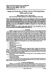
The generator polynomial coefficient is given by Tab 1. The figure 2 shows the input / output pins of the RS encoder. TAB 1: GENERATOR POLYNOMIAL COEFFICIENTS OF THE TWO RS CODES
(4)
The coding is systematic. The polynomials coefficients M (x), R (x) and C (x) can be represented either in the form of discrete values included between 0 and 15, or in the form of the power of α..
RS Code
C. RS decoder The code word C (x) transmitted may be subject to alterations due to the environment. The received code word C'(x) is equal to:
RS (15, 9)
0
b
j n k 1
j
g(x) x 6 9 x 5 12x 4 x 3 2 x 2 4 x 1 g(x) = x6 + 10 x5 + 15 x4 + 2x3 +4 x2 +3 x + 1
RS (15, 11)
(5) C' (x) [C(x) E(x)] Mod 2 . E (x) represents the expression of the errors polynomial. E(x)
Generator g(x)in linear and exponential representations
g(x) x 4 12x 3 4 x 2 x 6 g(x) = x4 + 15 x3 + 3 x2 + x + 12
x j bn k 1 x n k 1 ... b1 x 1 b0 x 0 (6)
Were b j GF (16) . III.
VHDL CIRCUIT DESIGN
The FPGA have known a great improvement in size and speed. Also, the FPGA constitute a more appropriate platform for the implementation of the applications of the error detecting correcting codes. Several studies on Reed Solomon "encoders/decoders" have already been carried out both at the university [5][6] or industrial [7][8] levels. The VHDL description of the Reed Solomon code is made so that every block of the proposed architecture is described in an independent entity. A. Encoding In this study, we have chosen the RS codes with parameters: (n, k, d) = (15, 9, 7) and (15, 11, 5). The circuit which instils the key encoding equation is given in figure1: C ( x) M ( x) * x 6 [ M ( x) * x 6 ] mod g ( x)
Figure 2: The input / output pins of the encoder.
Clk:
Timing clock signal.
Reset:
Signal allowing the reset the encoder.
Input:
Input signal of symbols to encode.
Out:
Output signal of encoded symbols.
Figure 3 shows the functional simulation of our (15, 9) encoder circuit, the latter has a complexity of 38 LEs.
Figure 3: Simulation of the encoder (coded message)
Figure 1: Encoder circuit for the RS (15, 9, 7)
B. Decoding For decoding we have used the following architecture:
34 | P a g e www.ijacsa.thesai.org
(IJACSA) International Journal of Advanced Computer Science and Applications, Vol. 4, No.1, 2013
σ(x)
S(x) Syndrome calculation
Euclid algorithm
Error locator
ω(x)
The Euclid algorithm allows to calculate these polynomials. The positions of the errors are located at the roots of the error locator polynomial which are calculated by brute force using the Chien-search. The error values are then calculated using Forney algorithm. The circuit represented in figure 5 reflects Euclid algorithm.
Error evaluator
Errors corrected
Decoded information
Figure 4: The Architecture Used For The (15, K, D) Reed Solomon Decoder.
Syndrome S(x) A syndrome for a Reed Solomon code is a polynomial with 2 * t coefficients (table 2) that depend only errors and are calculated by substituting 2 * t roots of the polynomial generator in C'(x). d 1
S( x ) S i x i 1
i 1
S1 S 2 x S 3 x ... S d 1 x 2
d 2
(7)
Figure 5: Euclid Algorithm Embedding Scheme. (w: Evaluator polynomial coefficient) (x: Locator polynomial coefficient)
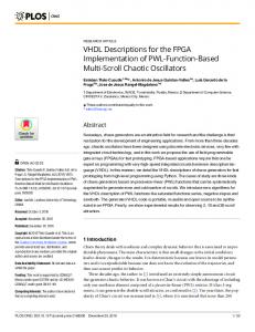
Performance of Reed-Solomon code The Figure 6 shows the performances of RS decoders (15.9) and RS (15.11), altered by AWGN channel noise with a BPSK modulation. IV.
Si C' ( i -1 )
et i 1, d 1
TAB 2: SYNDROME POLYNOMIAL COEFFICIENTS FOR THE RS CODES Code RS
S(x)
The methodology of simulation adopted in this work is to form the codeword C (x) using the encoding algorithm. The errors Injection consists of adding modulo 2 the codeword C(x) and the error polynomial E(x). The simulation example treats the case of a message with two errors. The codeword to be transmitted is the following sequence depending on the chosen code:
1, , 4 , 2 , 8 , 5 , 10, 3 , 14.
S(x) 4 x 5 14x 4 6 x 3 2 x 2 4 x 12
RS(15, 9) case
TESTS AND RESULTS
Or
1,, 4 , 2 , 8 , 5 , 10 , 3 , 14 , 9 , 7 0
10
RS(15,9) RS(15,11) -1
10
6 x 3 2 x 2 4 x 12
-2
10
Polynomial locaters and evaluators. The decoding method of Reed Solomon codes is based on the solving of key equation:
( x ) S( x )( x ) mod( x
2t
BER
RS(15, 11) case
-3
10
-4
10
) -5
10
where S (x): Syndrome polynomial. σ(x) : Error locator polynomial.
-6
10
(x) Error evaluator polynomial
0
1
2
3
4 SNR (dB)
5
6
7
8
Figure 6: Performances Of The RS Decoder
35 | P a g e www.ijacsa.thesai.org
(IJACSA) International Journal of Advanced Computer Science and Applications, Vol. 4, No.1, 2013
The message at the output of the two encoders is shown by table 3.
Figure 7b: Syndrome Of The Received Message Of Code RS(15,11)
Tab 3:The codeword at the output of the two encoders Code RS
The codeword at the output of the encoders
RS(15, 9)
1, , 4 , 2 , 8 , 5 , 10, 3 , 14, 14, 3 , 14, 4 , 9 ,0.
RS(15, 11)
1,, 4 , 2 , 8 , 5 , 10 , 3 , 14 , 9 , 7 , 4 , 0 , 6 , 6 .
The received message is affected by two errors in positions 13 2 and 9 with the amplitudes and respectively. The received message is:
1, , 4 , 2 , 8 , 7 , 10 , 3 , 14 , 14 , 3 , 14 ,1, 9 ,0. or 1,, 4 , 2 , 8 , 7 , 10 , 3 , 14 , 9 , 7 , 4 , 4 , 6 , 6 .
Figure 8a: Error Locator And Evaluator Polynomial (w: Evaluator polynomial coefficient) (x: Locator polynomial coefficient) RS (15, 9)
Or in decimal: 1, 2, 3, 4, 5, 11, 7, 8, 9, 9, 8, 9, 1, 10, 0. Or 1, 2, 3, 4, 5, 11, 7, 8, 9, 10, 11, 3, 3, 12, 12 The figure 7 shows the syndrome coefficients and the figure 8 shows the coefficients of the two polynomials (x) and σ(x). The positions of the errors are located in the figure 9.
Figure 8b Error locator and evaluator polynomial (w: Evaluator polynomial coefficient) (x: Locator polynomial coefficient) for RS(15,11) code
Figure 7a: syndrome of the received message of code RS(15,9)
Figure 9a: Detection of the positions and the amplitudes of the two errors for RS (15, 9) code
36 | P a g e www.ijacsa.thesai.org
(IJACSA) International Journal of Advanced Computer Science and Applications, Vol. 4, No.1, 2013
position and the correction of errors (1 cycle). For the case of (15, k, d) Reed Solomon code the operations require a latency of 5 Timing Clock cycles. As for the architecture adopted in [1], 8 Timing Clock cycles are required. The area occupied for the decoder for the (15, 9, 7) RS code is approximately of 972 LEs, and 868 LEs for the decoder of (15, 11) code RS. That is to say, we have reduced the area occupied in relation to the results in [1] [2] [9] [10]. V.
Figure 9b : Detection Of The Positions And The Amplitudes Of The Two Errors For RS(15,11) Code
The Altera’s FPGA FLEX10K on which we separately tested the different blocks, from the beginning, contains 1728 LEs and 189 input / output pins. The chosen encoder/decoder architecture, presented in the previous sections, was described in VHDL and embedded on FPGA (EPF10K30RI2404) using the software Quartus II from the Altera company. The area occupied by each circuit is given in the following table 4: TAB 4: THE AREA OCCUPIED BY DIFFERENT BLOCKS
LEs number RS(15, 9) case Syndrome computing Euclid algorithm Errors positions detection and Errors values calculation
175 286
LEs number RS(15, 11) case 114 243
511
511
The architecture chosen for this implementation reduces the number of cycles N necessary to have decoded data:
N N1 N 2 N 3
N 1 : Number of Timing Clock cycles needed in calculating the syndrome (1 cycle in our case).
N 2 : Number of cycles to calculate σ(x) and (x) (3 cycles).
N 3 : Number of cycles necessary to determine the
CONCLUSION
The design of the encoder/decoder was described in VHDL and validated on FPGA (type FLEX10K30) using the software Quartus II of the company Alteras. The results showed that the area occupied and the latency is very convincing. Indeed, we have decreased the latency and the area occupied by adopting architecture in which each block is pipeline and/or parallelized. REFERENCES [1]
S.Najah et M.Mrabti."Conception VHDL et implémentation sur FPGA du code Reed Solomon(15,k,d),traitement de signal, vol. 22, N° 2, p. 149-155. [2] A Dandache, T Vallino, F Onteiro et J.P Delahaye "code Reed Solomon (127,k,d) avec effacement : simulation et conception sur réseaux de circuits programmables FPGA " traitement de signal, 1999, volume 16, n°4, pp 331-341. [3] H. Lee and A. Azam " pipelined recursive modified Euclidean algorithm block for low-complexity, high-speed Reed Solomon decoder", ELECTRONICS LETTERS 18th September 2003 Vol. 39 No. 19. [4] Hsie-Chia Chang, Ching-Che Chung, Chien-Ching Lin, and Chen-Yi Lee "A High Speed Reed Solomon decoder Chip using Inversionless Decomposed Architecture for Euclidean Algorithm", ESSCIRC, Issue, 24-26 Sept. 2002, p. 519-522. [5] A Dabbagh "Etude et conception d’un circuit de détection d’erreurs en transmission d’informations numériques". PhD Thesis; Uuniversité de Rennes I, France (1995). (In French) [6] S Najah "codes détecteurs d’erreurs implémentation sur des circuits de type FPGA en utilisant le langage VHDL". PhD Thesis, Faculté des sciences Dhar Mehraz, Fez, Morocco Jan. 2006 (In French) [7] "Reed Solomon decoder". Lattice Semiconductor Corporation 2012. http://www.latticesemi.com/products/intellectualproperty/ipcores/reedso lomondecoder.cfm [8] Aha 4011 : "10 Mbytes/sec Reed Solomon error correction device. Product specification. Advanced Hardware Architectures", 20 july 1998. http://www.datasheetarchive.com/AHA4011*-datasheet.html. [9] A.Hikmat “ Implementation of Reed Solomon Encoder/Decoder Using FPGA”, Journal of Engineering and Development, Vol. 10,N°3, September 2006. [10] B.Tiwari and M.Rajesh, “FPGA Implementation of RS Codec for digital Video Broadcasting” VSRD-IJEECE, Vol. 2, 2012, 86-77
37 | P a g e www.ijacsa.thesai.org