74
ECTI TRANSACTIONS ON ELECTRICAL ENG., ELECTRONICS, AND COMMUNICATIONS VOL.5, NO.2 August 2007
VLSI Design of High-Throughput SISO-OFDM and MIMO-OFDM Baseband Transceivers for Wireless LAN Networks Shingo Yoshizawa 1 , Yoshikazu Miyanaga2 , Nobuo Hataoka 3 , Baiko Sai 4 , Norihisa Takayama 5 , Masaki Hirata 6 , Hiroshi Ochi7 , and Yoshio Itoh 8 , Non-members ABSTRACT
1. INTRODUCTION
This paper describes a VLSI design of highthroughput OFDM transceivers targeted to future wireless LAN systems. The optimum parameters composing a new packet OFDM frame are discussed by expanding the IEEE802.11a standard. The proposed system provides a maximum transfer rate of 600 Mbps by use of an 80-MHz occupied bandwidth and a MIMO technique. The SISO-OFDM and MIMO-OFDM transceivers have been designed according to the proposed OFDM format. A lowlatency and full-pipelined architecture enables a realtime processing of OFDM modulation/demodulation and MIMO detection. In the MIMO detection, the circuit structures of zero-forcing and MMSEV-BLAST algorithm in a 2 × 2 MIMO configuration are presented. The SISO-OFDM and MIMOOFDM transceivers have been implemented to a 90nm CMOS technology. It performed small implementation logic size and low power consumption after a real LSI evaluation. The circuit behavior of the OFDM transceivers has been verified by using the FPGA prototyping platform that executes both digital and analog OFDM baseband transmissions.
Wireless technologies, such as digital broad casting, wireless LAN, and wireless PAN, have enabled high-speed data transmission in home and personal networks. The IEEE802.11a standard supports a maximum of 54 Mbps at a 20-MHz frequency band by using orthogonal frequency division multiplexing (OFDM) [1]. For the standardization of next generation wireless LAN networks proceeded by IEEE802.11 Task Group n (TGn), the Enhanced Wireless Consortium (EWC) group sets a goal to achieve data rates of more than a few hundred using a multiple-input and multiple-out (MIMO) technique [2]. The EWC proposal indicates four main modifications from the IEEE802.11a standard to achieve a 600-Mbps data rate, i.e., the adoption of a 40MHz occupied bandwidth, a 400-ns short guard interval, a 5/6 coding rate and a 4 × 4 MIMO configuration. On the other hand, our research project supported by STARC1 has developed a comparable wireless OFDM system where this project mainly has focused on establishing high-speed wireless data links between information home appliances, e.g., digital data transmission of advanced high-definition digital video graphics. The proposed system achieves the same maximum data rate of 600 Mbps by use of an 80-MHz occupied bandwidth and a 2x2 MIMO configuration. The proposed system occupies the double signal bandwidth of the EWC proposal in frequency utilization. However, the EWC proposal has the following technical difficulties to transmit the above 600-Mbps data: First, it was difficult to build up a hardware that performs real time frequency-domain MIMO channel estimation and coding because of the large hardware complexity and high power consumption. Second, the use of a 5/6 coding rate is not sufficient for error correcting in a Viterbi decoder. Low density parity check code (LDPC) and turbo decoders improve transmission performance as alternative decoding schemes, however increase complexity and must deal with their increased power.
Keywords: Wireless, OFDM, MIMO, VLSI Design, Digital Circuit Manuscript received on January 30, 2007 ; revised on May 7, 2007. 1,2 The authors are with Graduate School of Information and Science Technology, Hokkaido University, Sapporo 060-0814, Japan, Emails:
[email protected] and
[email protected] 3 The author is with the Central Res. Lab., Hitachi Ltd., Tokyo 185-8601/Tohoku Institute of Tech., Sendai 982-8577, Japan, Email:
[email protected] 4 The author is with the LSI Product Development Headquarters, Rohm Co.Ltd., Kouhoku-ku, Yokohama 222-8575, Japan, Email:
[email protected] 5 The author is with the SANYO Semiconductor Co.,Ltd., Oizumi-machi, Ora-gun, Gunma 370-0596, Japan, Email:
[email protected] 6 The author is with the SANYO Semiconductor Co.,Ltd., Oizumi-machi, Ora-gun, Gunma 370-0596, Japan, Email:
[email protected] 7 The author is with the Dept. of CSE, Kyushu Inst. of Tech., Kawazu, Iizuka, Fukuoka 820-8502, Japan, Email:
[email protected] 8 The author is with the Dept. of Electrical Electronic Eng.,
Tottori University, Koyama-minami, Tottori 680-8522, Japan, Email:
[email protected] 1 Abbreviation of Semiconductor Technology Academic Research Center in Japan.
VLSI Design of High-Throughput SISO-OFDM and MIMO-OFDM Baseband Transceivers for Wireless LAN Networks
Table 1: Principal parameters in a packet OFDM system. K Fb Fn Tg Ns Nb R
DFT size Bandwidth (Hz) Guard carrier bandwidth (Hz) Guard interval (s) Number of data subcarriers Coded bits per subcarrier Coding rate
Data rate (Mbps)
300 250
Table 2: Frame format in the proposed OFDM system. Sampling period Number of FFT/IFFT points Number of data subcarriers Number of pilot subcarriers PLCP duration (short & long preambles) Symbol duration FFT/IFFT window duration Guard interval duration Subcarrier frequency spacing
350 K=64 K=128 K=256 K=512 K=1024 K=2048
75
12.5 ns 512 480 20 16 µs 7.2 µs 6.4 µs 0.8 µs 0.1563 MHz
Table 3: Transmission modes and data rates of the STARC-SISO and the STARC-MIMO.
DFT size 200
Mode
Modulation
150
1 2 3 4
QPSK 16-QAM 64-QAM 64-QAM
100
Coding Rate 1/2 1/2 1/2 3/4
SISO (Mbps) 67 133 200 300
2 × 2 MIMO (Mbps) 133 266 400 600
50 0 20
30
40
50
60
Bandwidth (MHz)
70
80
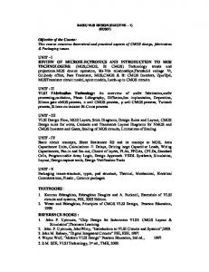
Fig.1: Data rate estimate by a function of a DFT size and a bandwidth.
This paper describes the total VLSI design of the proposed OFDM system, i.e., SISO-OFDM and MIMO-OFDM transceivers. Their results indicate that our proposed system can provide realistic instances in transmission performance and implementing hardware. A new OFDM frame format in the proposed system is discussed in Section II. Section III reports the simulation results in transmission performance comparing the EWC proposal with the proposed system. Section IV and V indicate a low-latency and full-pipelined architecture in order to enable realtime operations of OFDM demodulation/modulation and MIMO detection, respectively. The MIMO detection circuits based on zero-forcing and MMSEV-BLAST techniques are described. Section VI reports the VLSI implementation results of the designed transceivers in a 90-nm CMOS process, where circuit size and power dissipation are evaluated. Section VII introduces the FPGA prototyping platform that performs both digital and analog OFDM baseband transmissions to verify circuit behaviors of the OFDM transceivers. Section VIII summarizes the key points and mentions a future work. 2. PROPOSED OFDM SYSTEM The optimum parameters composing a new OFDM frame format are discussed in this paper. In order to realize a 600-Mbps data rate system, we first consider the OFDM parameters of a SISO-OFDM system
with a 300-Mbps data rate. The 2 × 2 MIMO-OFDM system processes two data streams and doubles the above date rate. For the SISO-OFDM system, we presented the data rate estimate for variable OFDM parameters by expanding the IEEE802.11a standard in [3]. The final representation is given by D(K, Fb , Fn , Tg , Nb , R) = ³ Fn ´ Fb K 1− ·Nb · R · . Fb K + Fb · Tg
(1)
Table 1 enumerates the parameters in the above equation. For the four parameters of Fn , Tg , Nb , and R, we adopt the same values used in the IEEE802.11a standard: The guard carrier bandwidth Fn is 4 × 10⁶ (Hz). The guard interval Tg is 8 × 10⁻⁷ (s). The coded bits per subcarrier is Nb = 6 (bits). The coding rate is R = 3/4. By substituting for above parameters, the estimate equation is transformed into a function given by a DFT size and a signal bandwidth. Figure 1 shows the estimates of data rates for variable DFT points and signal bandwidths. A 64-point DFT reaches around 60 Mbps in a 20-MHz bandwidth. However, the 64-point DFT is not sufficient in increasing the data rate for an 80-MHz bandwidth. A 512-point DFT achieves 300 Mbps in an 80-MHz bandwidth. Therefore, the proposed OFDM system employs the 512-point FFT/IFFT used for OFDM modulation/demodulation. Table 2 shows the proposed OFDM frame format. The subcarrier frequency spacing is about a half of that in the IEEE802.11a standard. The principal transmission modes and their data rates are depicted in Table 3, where the “STARC-SISO” and the “STARC-MIMO” modulate/demodulate one and two data streams, respectively.
76
ECTI TRANSACTIONS ON ELECTRICAL ENG., ELECTRONICS, AND COMMUNICATIONS VOL.5, NO.2 August 2007
10
Table 4: Simulation parameters of the EWC proposal and the STARC-MIMO.
GI Length
FFT/IFFT Size
STARC-MIMO
400 ns
800 ns
40 MHz
80 MHz
128
512
Antenna Structure (Tx, Rx)
4, 4
2, 2
2, 2
MIMO Detection
MMSE-VBLAST
MMSE-VBLAST
ZeroForcing
Coding
Coding Rate Decoding
5/6
Data Bits per Symbol (DBPS) Number of the OFDM symbols Packet Size
Maximum Data Rate
-1
10
BER
Bandwidth
EWC Proposal
Convolutional Coding
0
-2
10
-3
10
4x4 MIMO-OFDM IEEE802.11n (BLAST-MMSE) 2x2 STARC-MIMO (V-BLAST-MMSE) 2x2 STARC-MIMO (Zero-Forcing)
-4
10
15
20
25
64-State Viterbi Algorithm 2160
30
35
40
45
50
SNR (dB)
3/4
Fig.2: BER performance in the EWC proposal and the STARC-MIMO systems.
4 1000 bytes
(A) Encoding & Mapping
(D) GI/PLCP Generation
600 Mbps (E) Pre-FFT SRAM
(C) FFT/IFFT & Channel Equalization
(F) Post-FFT SRAM
Table 5: Channel Environments.
Modulation Channel model Doppler frequency Delay profile RMS delay spread
64-QAM 18-path Rayleigh fading 20 Hz TGn Channel D 50 ns
3. TRANSMISSION PERFORMANCE BER performance is compared the proposed system with the EWC proposal by baseband simulation. The simulation parameters in the 600-Mbps transmission modes listed in Table 4. The EWC proposal uses a 128-point FFT and a 5/6 coding rate. The proposed system is evaluated by taking the 2×2 MIMO-OFDM systems based on zero-forcing (ZF) and MMSE-VBLAST detection techniques. Data bits per symbol (DBPS), the number of OFDM symbols, and a packet size is the same between the EWC proposal and the STARC-MIMO. The conditions of multipath fading environments are listed in Table 5. The multipath delay profile is based on the TGn Channel D [4]. Figure 2 shows the simulation results of BER performance. The 2×2 STARC-MIMO systems outperform the EWC proposal by 6 to 7 dB and more than 10 dB in SNR for BER=10−2 and BER=10−3 , respectively. The use of a 5/6 coding rate is considered to be insufficient to remove bit errors by Viterbi decoding under multipath fading channels, as is observed from these results. 4. TRANSCEIVER ARCHITECTURE Since the number of data subcarriers is ten times large as that of IEEE802.11a standard, a new VLSI architecture is to be discussed to deal with such an
(B) Frame Synchronization
(G) Soft-Out Demapping
Transmitter Receiver
(H) Viterbi Decoding
Fig.3: Block diagram in the SISO-OFDM transceiver. (A) Encoding & Mapping
(E) PreTransform Memory
(D) GI/PLCP Insertion
(C) FFT/IFFT
(F) PostTransform Memory
(G) MIMO Detection
(B) Timing Synchronization
(H) DeMapping
(I) Viterbi Decoding
Transmitter Receiver
Fig.4: Block diagram in the 2 × 2 MIMO-OFDM transceiver.
increased complexity. The proposed system has a sampling rate of 80 Msps. A recursion procedure is not suitable for a real-time processing because a high clock rate makes it difficult to design an application specific circuit and consumes large power. We apply a full-pipelined architecture which processes one data per cycle at the minimum frequency of 80 MHz. Figure 3 shows a overall block diagram in the SISO-OFDM transceiver consisting of processing blocks (A) to (H). The two SRAM blocks adjusts data communication timing between adjoined processing blocks. For instance, while the block (A) sends mapped data to the neighbor SRAM block (E), the FFT/IFFT block (C) reads out mapped data in the previous symbol. As long as the blocks of (A) and (C) finish their own processing within symbol duration,
VLSI Design of High-Throughput SISO-OFDM and MIMO-OFDM Baseband Transceivers for Wireless LAN Networks
Long Training Short Preamble Symbols
S
Channel Estimation (1 stage)
Data Symbols
T11
T21
D11
D21
DK1
T12
T22
D12
D22
DK2
Channel Estimation and Pre-processing
MIMO Detection
Latency
D
from FFT
Channel Estimation
T22
Η
H 11
G11
H 12
−H 12
G12
H 21
−H 21
G21
H 22
H 22
1
δδ *
δ =H 11H 22−H 12H 21
Fig.6: Circuit structure in the ZF algorithm.
−1
Memory
Fig.5: OFDM frame structure, block diagram and processing timing chart in the MIMO detection block.
D
Table 6: MIMO detection complexity in the EWC proposal and the STARC-MIMO. Antenna (Tx, Rx) 2, 2
2, 2
4, 4
Channel Estimation and Pre-processing
H
G1 G
EWC Proposal
G22
δ*
T1 T 2
STARC-MIMO
1
δδ *
H 11
δδ *
G=
G = H ′′ *
H ′′ = H ′ * δ *
H′
G
H Inverse Matrix
y
MIMO Detection
T1 ,T 2
Inverse Matrix Calculation (7 stages)
T11 T12 T21
77
k
W
a
2b
W
Complexity
ya
yb
Zero-Forcing
22
αˆ a
αˆ b
MMSE-V-BLAST
23
MIMO Detection
43
no data collision occurs between these blocks. The start timing in each block is given by the start point of FFT/IFFT period and determined by the frame synchronization block (B). In the FFT/IFFT block, a pipeline FFT using a hybrid Radix-2 and Radix-22 Single-path Delay Feedback (R2SDF and R22 SDF) architecture [5] is implemented to the system. The Viterbi block decodes parallel data sequences by 3 bits per clock. The three Viterbi decoders perform their decoding for supporting the maximum data rate of 64-QAM demodulation, where they were designed in the previous research [6]. The 2 × 2 MIMO-OFDM transceiver is shown in Fig. 4. The processing blocks from (A) to (I) are duplicated except the time synchronization block and the MIMO detection block. 5. MIMO DETECTION 5. 1 Required timing constraint The OFDM frame structure, the block diagram, and the processing timing chart in the MIMO detection block are illustrated in Fig. 5. The MIMO frame consists of the short symbol, the long training symbols, and the data symbols. The long training symbols Tij with the i-th symbol index and the j-th stream are used for the estimation of a MIMO channel matrix. The channel matrix H is obtained from an orthogonal training where this equation is described
(10 stages) 2a
b
Algorithm MMSE-V-BLAST
G
r ′a
r ′b
yˆ a
yˆ b
(6 stages)
y Fig.7: Modified processing procedure in MMSE-VBLAST algorithm.
as: H11 H12 H21 H22
= (T11 − T21 )/2 = (T11 + T21 )/2 = (T12 − T22 )/2 = (T12 + T22 )/2.
(2) (3) (4) (5)
The MIMO detection block performs the channel estimation and the inverse matrix calculation given by G=H −1 (called as “pre-processing”) at receiving the long training symbols. At receiving the data symbols of D, the MIMO block decodes the transmitted data by y=GD. If the MIMO decoding is immediately applied to the first data symbol, the channel estimation and the MIMO detection should be completed before receiving the first data symbol. Hence, the permitted latency duration is within the guard interval (see “Latency” in Fig. 5). The challenging work is to realize a real-time MIMO detection which performs a large complexity of inverse matrix calculation so that the MIMO channels for all the sub-carriers can be calculated
78
ECTI TRANSACTIONS ON ELECTRICAL ENG., ELECTRONICS, AND COMMUNICATIONS VOL.5, NO.2 August 2007
on time. Table 6 shows the MIMO detection complexity per subcarrier in the EWC proposal and the STARC-MIMO, where QR decomposition algorithm is utilized for calculating an inverse matrix. We have developed the 2x2 MIMO-OFDM detection blocks in zero-forcing and MMSE-V-BLAST techniques. As well as the other processing blocks, a full-pipeline architecture is introduced. The designed circuits tend to increase circuit area; however they satisfy the above timing constraint and indicate practical instances in developing hardware.
Table 7: Circuit performance of the SISO-OFDM Transceiver. Circuit Area (μm2)
No. Logic Gates
Coder & Mapping
10143
3381
System Control
where hij and gij are factors of the channel matrix H and the inverse matrix G, respectively. The QR decomposition is generally utilized in the inverse matrix calculation in order to reduce a complexity. However, the complexity is not large as for a 2x2 MIMO configuration. Figure 6 shows the circuit structure of the ZF algorithm. This circuit operates a 8-stage pipeline including a complex divide operation. The total latency is 11 cycles including memory access. It can satisfy the above timing constraint for the guard interval of 64 cycles (12.5-ns clock period × 64 cycles = 800 ns). The numbers of real and complex multipliers are 8 and 11, respectively. 5. 3 MMSE-V-BLAST The original V-BLAST is expressed as a recursive procedure [7]. In our architecture, the procedure is modified to introduce pipeline and concurrent processing. In the 2x2 MIMO, the modified procedure is described as follows: G1 G2a G2b wa wb y¯a y¯b α ˆa α ˆb r´ a r´ b yˆa yˆb k
= = = = = = = = = = = = = =
H+ + (H)2 + (H)1 (G1 )1 (G1 )2 wa T r wb T r Q[¯ ya ] Q[¯ yb ] r−α ˆ a (H)1 r−α ˆ b (H)2 G2a r´ a G2b r´ b arg mink(G1 )j k2 j
(7) (8) (9) (10) (11) (12) (13) (14) (15) (16) (17) (18) (19) (20)
0.11
1668
80573
26858
1.44
5.26
FFT/IFFT & Equalizer
838144
279381
39.30
39.92
SRAMs for Pre-FFT
285576
95192
10.06
9.64
SRAMs for Post-FFT
285576
95192
Timing Synchronization GI・PLCP Signals
Soft Demapper
Viterbi Decoder
The zero-forcing (ZF) algorithm is simply achieved by computing an inverse matrix G. The inverse formula is given by µ µ ¶ ¶ 1 g11 g12 h22 −h12 , (6) = g21 g22 h11 h22 − h12 h21 −h21 h11
0.11
Power RX (mW)
5006
Total
5. 2 Zero-forcing
Power TX (mW)
13854
0.29
4618
3315
0.34
9.12
0.10
0.13
9.36
804624
1105
268208
0.01
0.18
3.81
35.88
2326811
775603
64.48
100.58
Table 8: Circuit performance of the zero-forcing MIMO-OFDM Transceiver. System Control
Circuit Area (μm2)
No. Logic Gates
Power TX (mW)
Power RX (mW)
20286
6762
0.49
0.10
388669
70.50
73.32
16976
0.43
118353
Coder & Mapping
Timing Synchronization FFT/IFFT
81967
1166008
39451 27322
0.01
1.42
MIMO Detection
1114612
371537
SRAMs for Pre-FFT
573584
191195
13.76
6480
2160
0.02
GI・PLCP Signals
SRAMs for Post-FFT Soft Demapper
Viterbi Decoder
573584 1600206
Total
4256008
( y=
50928
T
(¯ ya , yˆb ) T (ˆ ya , y¯b )
191195 533402
1418669
5.05
14.02 7.36
113.06
if k=1 , otherwise
1.33
4.84
26.38 0.10
14.00
14.06 0.35
71.20
205.68
(21)
where (H)j is the j-th column of H and + denotes an inverse matrix operation based on a MMSE criterion. The inverse matrices of G2a and G2b are precomputed before the MIMO detection at Eqs. (8) and (9). This pre-computation converts a recursive procedure into a one-time procedure. It prepares both candidates of (¯ ya , yˆb ) and (ˆ ya , y¯b ) for optimal detection ordering. Figure 7 depicts the modified procedure in MMSE-V-BLAST algorithm, which is applied to the MIMO detection block. While the two candidates are calculated at Eqs. (10) to (19), the channel order information of k is simultaneously computed at Eq. (20). The channel estimation and the pre-processing finish within a 13-cycle latency including memory accesses. The numbers of real and complex multipliers require 16 and 27, respectively. 6. VLSI IMPLEMENTATION In the VLSI implementations of the SISO-OFDM and the 2x2 MIMO-OFDM transceivers, their minimum wordlengths have been explored by using a fixed point simulation [8]. The transceivers have been designed by using Verilog in RTL level design and implemented to logic gates on a 90-nm CMOS standard cell library. The operating clock frequency is 80 MHz,
VLSI Design of High-Throughput SISO-OFDM and MIMO-OFDM Baseband Transceivers for Wireless LAN Networks
To RF
Table 9: Circuit performance of the MMSE-VBLAST MIMO-OFDM Transceiver. System Control
SRAMs for Pre-FFT
SRAMs for Post-FFT Soft Demapper
Viterbi Decoder Total
20286
6762
0.49
0.10
118353
39451
0.01
1.33
224887
74962
6.02
11.79
1166008
388669
70.50
73.32
16976
0.43
3480276
1160092
573584
191195
13.76
14.00
6480
2160
0.02
0.35
50928
573584 1600206 7814592
191195 533402
2600364
7.05
14.02 7.36
119.66
79.98 0.10
14.06 71.20
266.23
DACs
DACs
Interpolate & FIR
OFDM Transmitter
Transmitter Transmit Receive Test
ADCs Decimate & FIR
OFDM Receiver
IDE Cable
MIMO Detection
GI・PLCP Signals
Power RX (mW)
PC IF
FFT/IFFT
Power TX (mW)
Test Data
Timing Synchronization and SNR Estimation
No. Logic Gates
From RF
Random Signal
Coder & Mapping
Circuit Area (μm2)
79
Demapper
Receiver Viterbi Decoder
Decoder
Fig.9: Block diagram of the FPGA board.
Fig.8: Photographs of the FPGA board and the RF modules.
which is common to the transceivers. The power voltage is 1.1V for all devices. Circuit area, logic gate counts, and power dissipation are reported in Table 7, 8 and 9. The SISO-OFDM transceiver was designed in 0.78 millions of logic gates with 110 mW of maximum power consumption. The Viterbi decoder has been re-designed to reduce both circuit area and power dissipation, compared to the previous work [9]. The zero-forcing MIMO-OFDM transceiver has 1.42 millions in logic gates and dissipates 206 mW in the maximum. The FFT/IFFT and Viterbi blocks have impact on the overall system. The MMSE-V-BLAST MIMO-OFDM transceiver has 2.60 millions in logic gates and increases dissipated power to 266 mW. The circuit size of the MIMO detection block in the MMSE-V-BLAST becomes about three times of the zero-forcing, However, it does not increase power consumption as much as circuit area because the MIMO detection is executed by a short period. 7. FPGA VERIFICATION Figure 8 shows the FPGA verification board used to verify circuit behavior of the OFDM transceivers and RF modules. Figure 9 shows the block diagram of the FPGA board in the SISO-OFDM system. The FPGA board activates three chips of the transmitter, the receiver, and the Viterbi decoder, which is based on Xilinx Vertex II-Pro XC2VP70. We have added an interpolator, a decimator, a random signal generator, and bus interfaces to communicate with a PC. The interpolator and the decimator require 100-MHz
clock frequency and the other modules operate at its half clock speed. The current FPGA board enables baseband transmission via ADCs and DACs. BER and PER can be obtained from this baseband transmission.
8. CONCLUSION This paper has described the VLSI design of the SISO-OFDM and the MIMO-OFDM transceivers achieving a 600-Mbps data rate for wireless LAN networks. The proposed frame format is based on the use of 512-point FFT/IFFT and an 80-MHz occupied signal bandwidth. The 2x2 MIMO configuration doubles the data rate of the SISO-OFDM system. Compared to the 600-Mbps transmission mode in the EWC proposal, the STARC-MIMO has superior transmission performance and lower complexity in the MIMO detection. In the hardware architecture, the SISO-OFDM and the MIMO-OFDM transceivers have been designed by the policy of applying full-pipeline and concurrent processing. The zero-forcing and MMSE-V-BLAST techniques have been implemented to hardware as practical instances. The OFDM transceivers have been implemented to a 90-nm CMOS process and evaluated on circuit area and power dissipation. The FPGA board has been presented to verify circuit behaviors and execute baseband transmission. As a future work, the VLSI implementation of a 4×2 MIMO configuration will be discussed. The 4×2 MIMO-OFDM system is given by a LSTBC system [10] which combines layered spacetime (LST) [11] and space-time block coding (STBC) [12] techniques. The 4 × 2 MIMO has much better transmission performance than the 2×2 MIMO. This utilization is assumed in downlink transmission when a wireless station has four transmission antennas.
80
ECTI TRANSACTIONS ON ELECTRICAL ENG., ELECTRONICS, AND COMMUNICATIONS VOL.5, NO.2 August 2007
ACKNOWLEDGMENTS The authors would like to thank Research and Development Headquarters, Yamatake Corporation and the VLSI Design Education and Research Center (VDEC), Tokyo University for fruitful discussions. This study is supported in parts by Semiconductor Technology Academic Research Center (STARC), Project 308. References [1]
IEEE Std. 802.11a-1999, “Wireless LAN medium access control (MAC) and physical layer (PHY) specifications: high-speed physical layer in 5 GHz band,” 1999 Edition. [2] Enhanced Wireless Consortium publication, “HT PHY specification v1.27,” Version 1.27, Dec. 2005. [3] Shingo Yoshizawa, Yoshikazu Miyanaga et al.,“300-Mbps OFDM baseband transceiver for wireless LAN systems,” Proc. IEEE ISCAS2006, pp. 5455-5458, May 2006. [4] V. Erceg et al., “TGn channel models,” IEEE 802.11-03/940r4, May 2004. [5] Shousheng He and Torkelson M., “A new approach to pipeline FFT processor,” Parallel Processing Symposium, 1996, pp. 766-770, Apr. 1996. [6] Yasuyuki Hatakawa and Yoshikazu Miyanaga, “Robust LSI architecture and its high speed Viterbi decoder, ” IEEE International Midwest Symposium on Circuits and Systems (MWSCAS), Vol. 2, pp. 577-580, July 2004. [7] P. W. Wolniansky, G. J. Foschini, G. D. Golden, R. A. Valenzuela, “V-BLAST: an architecture for realizing very high data rates over the rich-scattering wireless channel” Proc. IEEE ISSSE98, Sep. 1998. [8] K. Han and B. L. Evans, “Wordlength optimization with complexity-and-distortion measure and its applications to broadband wireless demodulator design”, Proc. IEEE ICASSP2004, Vol. 5, pp. 37-40, May 2004. [9] Shingo Yoshizawa and Yoshikazu Miyanaga, “VLSI implementation of high-throughput SISO-OFDM and MIMO-OFDM transceivers,” International Symposium on Communications and Information Technologies (ISCIT), No. T2D-4, Oct. 2006. [10] X. Zhuangm, F. W. Vook, S. R-Leveil, K. Gosse, “Transmit diversity and spatial multiplexing in four-transmit-antenna OFDM,” Proc. IEEE ICC2003, Vol. 26, pp.2316-2320, May 2003. [11] G. J. Foschini, “Layered space-time architecture for wireless communication in a fading environment when using multi-element antennas,” Bell Labs Tech. J., Vol. 1, pp. 41-59, 1996. [12] S. M. Alaomouti, “A simple transmit diversity technique for wireless communications,” IEEE
Journal on Select Areas in Communications, Vol. 16, No.8, pp. 1451-1458, Oct. 1998.
Shingo Yoshizawa He received the B.E., M.E. and Dr.Eng. degrees from Hokkaido University, Japan in 2001, 2003 and 2005, respectively. He is an Assistant Processor and currently working at the Graduate School of Information Science and Technology, Hokkaido University. His research interests are speech processing, speech recognition, wireless communication, and VLSI architecture.
Yoshikazu Miyanaga He received the B.S., M.S., and Dr.Eng. degrees from Hokkaido University, Japan in 1979, 1981, and 1986, respectively. From 1983 to 1987, he was a Research Associate at the Institute for Electronic Science, Hokkaido University. From 1987 to 1988, he was a Lecturer at the Faculty of Engineering of Hokkaido University. From 1988 to 1997, he was an Associate Professor there. He is currently a Professor at the Graduate School of Information Science and Technology, Hokkaido University. His current research interests are adaptive signal processing, non-linear signal processing, and parallel-pipelined VLSI systems.
Nobuo Hataoka He received the B.S.E.E. degree and the M. Sc. degree in Electrical and Electronics Engineering from Tohoku University, in 1976 and 1978, respectively, and the Ph.D in Engineering in 1992 from Tohoku University. He joined Central Research Laboratory, Hitachi Ltd. in 1978, and he spent one year from 1988 to 1989 as Visiting Researcher at Carnegie Mellon University in U.S.A. From 1989 to 1993, he was Laboratory Manager of Hitachi Dublin Laboratory in Ireland and after returning to HCRL in Japan he took management responsibilities as Chief Research Scientist. He is currently Professor of Tohoku Institute of Technology in Sendai, Japan. His research interests include media implementation on microprocessors, and algorithm development on speech recognition, speech synthesis, speech translation, and artificial intelligence. Dr. Hataoka is a member of the IEEE Acoustic, Speech, and Signal Processing Society, the Institute of Electronics, Information and Communication Engineers (IEICE), Japan, and the Acoustical Society of Japan. He is presidentelect in Information Systems Society of IEICE.
Baiko Sai He received the B.E. from Shanghai University in 1985, and received M.E. from Yokohama National University in 1991. He worked for Space and Science Ministry of China in Shanghai from 1985 to 1987. He worked as a system engineer in Pioneer Electronic Corporation Japan from 1990 to 1996 and as a system design manager in Philips Semiconductors from 1996 to
VLSI Design of High-Throughput SISO-OFDM and MIMO-OFDM Baseband Transceivers for Wireless LAN Networks
2001. The is a LSI product design manager in Rohm Co,.Ltd. His research interests are signal processing, communication, video processing and cryptogram.
Norihisa Takayama He received the B.E. and M.E. degrees in Electrical Engineering from Mie University, Japan in 1981 and 1983, respectively. He joined SANYO Electric Co., Ltd., in 1983. He has been engaged in research and development of VLSI design techniques for image processing and wireless communication systems. From 2006, he is working at SANYO Semiconductor Co., Ltd.
Masaki Hirata He received the B.S., M.S. degrees in electronics engineering from the University of ElectroCommunications, Tokyo in 1972 and 1974, and Ph.D. degree in electronics engineering from the University of Tokyo, Tokyo in 1991. He joined NEC Corporation, Kawasaki, Japan in 1974, where he has been engaged in the research of CMOS VLSI circuits design. He worked at STARC (Semiconductor Technology Academic Research Center) from 2000 to 2006. He is currently a senior manager in NEC Electronics Corporation. His research interests focus on System LSI architecture. Dr. Hirata is a member of the Institute of Electronics, Information and Communication Engineers of Japan.
Hiroshi Ochi He received the B.E. and M.E. degrees from Nagaoka Institute of Technology, and Ph.D. from Tokyo Metropolitan University, Japan in 1981, 1984, and 1992 respectively. He is a Processor at the department of CSE, Kyushu Institute of Technology His research interests are signal processing, wireless communication, and their VLSI implementation.
Yoshio Itoh He received the B.E. degree in electronics engineering from Osaka Institute of Technology, M.E. and D.E. degrees in electrical engineering from Osaka Prefecture University in 1979,1981 and 1991, respectively. He is now a Professor in the Faculty of Engineering, Tottori University, Japan. His research interests are in the area of digital signal processing and communication systems. From 2000 to 2004, He was an Associate Editor of Trans. on Fundamentals of IEICE. He is a member of the IEEE, IEICE and Acoustical Society of Japan.
81