the motion of and recognizing a moving object from a se- quence of time ... supported in part by National Aeronautics and Space Administration Under ... Vision also involves top-down and ... Section II contains a review of architectures proposed for ... The Connection Machine (CM) provides a NEWS network ...... Page 12 ...
1092
IEEE TRANSACTIONS
ON PARALLEL
AND
DISTRIBUTED
SYSTEMS,
VOL. 4, NO. 10, OCTOBER
1993
NETRA: A Hierarchical and Partitionable Architecture for Computer Vision Systems Alok
N. Choudhary,
Janak H. Patel, Fellow, IEEE, and Narendra Ahuja, Fellow, IEEE
Abstract- Computer vision is regarded as one of the most complex and computationally intensive problems. In general, a Computer Vision System (CVS) attempts to relate scene(s) in terms of model(s). A typical CVS employs algorithms from a very broad spectrum such as such as numerical, image processing, graph algorithms, symbolic processing, and artificial intelligence. This paper presents a multiprocessor architecture+ called “NETRA,” for computer vision systems. NETFLA is a highly flexible architecture. The topology of NETRA is recursively defined, and hence, is easily scalable from small to large systems. It is a hierarchical architecture with a tree-type control hierarchy. Its leaf nodes consists of a cluster of processors connected with a programmable crossbar with selective broadcast capability to provide the desired flexibility. The processors in clusters can operate in SIMD-, MIMD- or Systolic-like modes. Other features of the architecture include integration of limited data-driven computation within a primarily control flow mechanism, blocklevel control and data flow, decentralization of memory management functions, and hierarchical load balancing and scheduling capabilities. This paper also presents a qualitative evaluation and preliminary performance results of a cluster of NETRA.
effects and employ a model based recognition in addition to the interpretation needed for static images [7], [9]. Vision researchers have shown that pattern recognition techniques and bottom-up processing alone is not adequate for the above tasks [16]. Vision also involves top-down and knowledge-based processing. Between these two levels of abstraction, another level, known as “intermediate level” is normally introduced. It involves symbolic processing. Symbols range from extracted image characteristics such as edges or regions through perceptually useful groupings such as geometric figures and surfaces. Hence, vision algorithms are normally classified into three levels: low (sensory, image processing), intermediate (symbolic processing), and high (knowledgebased). B. Architectural Considerations
Index Terms-Computer vision, parallel architectures, parallel algorithms, partitionable architectures, performance evaluation. I.
INTRODUCTION
A. Computer k&ion vision has been regarded as one of the most complex and computationally intensive problems. A Computer Vision System (CVS) employs algorithms from a very broad spectrum such as numerical, signal processing, image processing, graph algorithms, symbolic processing, and artificial intelligence. A typical CVS using color images requires a processor capable of handling 23 Megabytes of input data per second, interpreting it to construct a three-dimensional model of the environment [S], [38]. An interpretation may require hundreds of objects of different types to be identified [ll]. Estimating the motion of and recognizing a moving object from a sequence of time varying images may further involve motion
C
OMPUTER
Manuscript received July 16,199l; revised August 10, 1992. This work was supported in part by National Aeronautics and Space Administration Under Contract NASA NAG-1-613. A. N. Choudhary is with the Department of Electrical and Computer Engineering, Syracuse University, Syracuse, NY 13244. J. H. Pate1 is with the Center for Reliable and High Performance Computing, University of Illinois, Urbana-Champaign, Urbana, IL 61801. N. Ahuja is with Beckman Institute, University of Illinois, UrbanaChampaign, Urbana, IL 61801. IEEE Log Number 9213476. 1045-9219/93$03.00
From a multiprocessor architecture perspective, an image understanding and computer vision tasks’ computational requirements can be described considering different abstract levels of processing. Low-Level Processing-Tasks in this class exhibit massive spatial parallelism which is suitable for both SIMD and MIMD computations. Computations are normally simple and data independent. Computations mainly involve numeric processing and manipulation of simple data structures (such as pixels). Communication requirements are structured. Communication may be local or global in the sense that the output may depend on a spatially local neighborhood of data (e.g., convolution), or it may depend on the entire input image data (e.g., 2D-FIT). Also, communication requires efficient broadcast and synchronization. Intermediate Level Processing-Computations in this category manipulate symbolic (e.g., tokens) as well as numeric data [39]. Computations are normally data dependent and irregular. They are suitable for medium to coarse grain parallelism. The available parallelism is dynamic and data dependent. Communication patterns can be regular as well as unstructured, depending on the data. Both local and global communication (including broadcasts) are required. Since computations are data dependent, independent decision making capabilities and distributed control are required. High-Level Processing-Tasks in this level of processing are normally top-down (model directed). Computations require both numeric as well as symbolic processing and 0 1993 IEEE
CHOUDHARY
et cd.: NETRA:
ARCHITECTURE
FOR COMPUTER
VISION
SYSTEMS
are suitable for MIMD coarse-grain parallelism. Computations are both data and model dependent, and are irregular. Communication is unstructured and irregular. Processors require accesses to shared data (which stores model and image information.) Furthermore, distributed control of processing as well as efficient mechanism to coordinate different activities is needed. An architecture for CVS’s should be capable of performing tasks from all levels of processing efficiently and synergistically. Hence, it needs to be flexible to be able to adapt to the required processing. Furthermore, a flexible communication structure is needed to allow different types of communication among various parts of an architecture. The architecture should allow a partition executing tasks from one level of vision to be reconfigured to perform a task from another level. This requires the architecture to be reconfigurable into the most suitable mode of operation (such as SIMD mode or MIMD mode) for a given task. Real-time vision and high performance requirements dictate that tasks from all levels exist and execute simultaneously in the system, and therefore, the architecture should be divisible into several partitions that can operate independently, yet interact with each other to exchange appropriate data and information. Top-down processing and load balancing requirements suggest a hierarchical and distributed control in the architecture [26]. Time-varying data or different sets of data may represent varying and unevenly distributed load. Therefore, efficient resource allocation, topology and data size independent mapping capabilities, and efficient load balancing capabilities are needed in the architecture. Finally, an architecture for such a complex problem should be modular. In this paper, we present a parallel architecture called NETRA for CVS’s. The architecture was originally proposed by Sharma, Patel, and Ahuja [28]. NETRA is a recursively defined tree-type hierarchical architecture, each of whose leaf nodes consists of a cluster of processors. Processors in a cluster are connected with a programmable crossbar with selective broadcast capability. The internal nodes of the architecture are scheduling processors whose functions are task scheduling, load balancing, and global memory management. The processors in clusters can operate in SIMD-, MIMD- or Systolic-like mode. Other features of the architecture include integration of limited data-driven computation within a primarily control flow mechanism, block-level control and data flow, decentralization of memory management functions, and hierarchical load balancing and scheduling capabilities.
1093
II. REVIEW O F ARCHITECTURES
A. SIMD Architectures Massively parallel SIMD multiprocessors are well suited for low-level and well structured vision algorithms that exhibit spatial parallelism at the pixel level. However, such architectures are not well suited for high-level vision algorithms because these algorithms require nonuniform processing, more complex data structures, and data dependent decision making capabilities. Meshes, array processors, hypercubes, and pyramids are some of the most common SIMD parallel processors proposed for image analysis and processing. In meshes, the processing elements are arranged in a square array. Examples of mesh connected computers include CLIP4 [ 121 and the MPP [3]. The Connection Machine (CM) provides a NEWS network for local communication and a hypercube network for long distance communication [17], [36]. Pyramid architecture was proposed to mimic multidimensional divide-and-conquer computations [ 11. However, it was discovered that while the pyramid structure was efficient for a large class of low-level image processing tasks, it was not efficient for higher level tasks [28]. Examples of pyramid architectures include PAPIA [6], SPHINX [24], MPP pyramid [27], and HCL Pyramid [35]. B. HierarchicallPartitionable/Reconfigurable
Architectures
Several hierarchical, partitionable, and reconfigurable architectures have been proposed (and some prototypes built). The following is a brief review of some of these architectures. TRAC is an experimental reconfigurable array computer proposed for scientific computations [22]. The available resources can be partitioned into several SIMD/MIMD partitions. The partitioning in TRAC is done by setting switches of the interconnection network to partition resources into blocks such that each resource is exactly part of one block. PASM is a partitionable SIMDMIMD architecture [31], [13]. PASM can be structured as one or more independent SIMD and/or MIMD machines of various sizes. PASM’s multistage network is a generalized cube network. PASM provides hierarchical control. Partitioning of processors and networks is performed by explicitly setting switches to the desired configuration. ZUA (Image Understanding Architecture) has been developed to embed three abstract levels of vision processing into an architecture [39]. It has a hierarchical structure. At the high level, IUA is a MIMD parallel processor. The low level is a Content Addressable Array Parallel Processor C. Organization (CAAPP) which operates in pure SIMD mode. It also has Section II contains a review of architectures proposed for a reconfigurable mesh with a local broadcast capability. The image processing and computer vision. A brief overview of intermediate level operates in synchronous-MIMD or MIMD hierarchical, partitionable, and reconfigurable architectures is mode. Communication and data transfer between different levels is achieved using a shared memory. also presented. Section III presents the architecture of NETRA Cedar is a multiprocessor architecture with a hierarchical and describes its components and their functions in detail. In Section IV, NETRA is critically examined with respect memory structure [20]. Cedar unifies distributed and shared to the CVS architectural requirements. Section V contains memory paradigms. It consists of multiple clusters (each preliminary results on the cluster performance. Finally, Section cluster being a multiprocessor) connected through an omega network to a global memory. VI summarizes the paper.
1094
IEEE TRANSACTIONS
ON PARALLEL
AND
DISTRIBUTED
VOL.
4, NO. 10, OCTOBER
1993
L
Other proposed multiprocessor architectures that have considered flexibility, partitioning and reconfiguration include CHiP [33], Non-Von [29], and REPLICA [23]. C. Other Architectures The CMU Warp processor [14] is a systolic array machine proposed and built for image understanding and scientific computations. The machine has a programmable systolic array of linearly connected cells. iWarp (next in the sequence to Warp) is a two-dimensional systolic and distributed memory architecture considered for image understanding and scientific computations [4]. It supports memory communication and systolic communication. Another architecture called “VisTA” (Vision Tri-Architecture) has been proposed for integrated vision systems which attempts to explicitly embed three levels of vision in the architecture [34]. General purpose shared and distributed memory multiprocessors have also been considered and evaluated [37] for image understanding and computer vision.
GLOBAL
SDP : Scheduling C : Processor
III.
SYSTEMS,
and Distributing
Cluster
AFCHITECTUI~E OF NETRA
M : Memory
Fig.
1.
INTERCONNECTION
Pnxeseor Module
Organization
Fig. 1 shows the architecture of “NETRA.” NETRA consists of the following components: 1) A large number (102-104) of Processing Elements (PE’s), organized into clusters of 16 to 64 PE’s each. 2) A tree of Distributing-and -Scheduling- Processors (SDP’s) that make up the task distribution and control structure of the multiprocessor. 3) A parallel pipelined shared Global Memory. 4) A Global Interconnection that links the PE’s and SDP’s to the Global Memory.
of NETRA.
SYNCHRONIZATION
BUS
TO
A. Processor Clusters The clusters consist of 16 to 64 PE’s, each with its own program and data memory. They form a layer below the SDP-tree, with a leaf SDP associated with each cluster. PE’s within a cluster also share a common data memory. The PE’s, the SDP associated with the cluster, and the common data memory are connected together with a crossbar switch. The crossbar switch permits point-to-point communications as well as selective broadcast by the SDP or any of the PE’s. Fig. 2 shows the cluster organization. A 4x4 crossbar is shown as an example of the implementation of the crossbar switch. The switches are controlled by control bits indicating the connection pattern. If a processor of SDP needs to broadcast, then all the control bits in its row are made one. In order to connect processor Pi to processor Pj, control bit (i, j) is set to one and the rest of the control bits in row i and column j are off. Details of the crossbar are discussed later in this section. Clusters can operate in a SIMD-, a systolic-, or an MIMDlike mode. Each PE is a general purpose off-the-shelf processor. In a SIMD mode, PE’s in a cluster execute identical instruction streams from private memories in a Iockstep fashion. Since instruction streams are supplied from the PE’s private memory (as opposed to being broadcast by a controller), this type of execution represents is SPMD
--
UNIDIRECTIONAL CROSSBAR
DSP CDM
PE : PROCESSOR CDM : COMMON
Fig.
2.
Organization
M : LOCAL DATA
MEMORY
MEMORY
of processor
cluster.
(Single-Program-Multiple-Data) execution in lock-step. In the systolic mode, PE’s repetitively execute a set of instruction on data streams from one or more PE’s. In both cases, communication between PE’s is synchronous. The advantage of providing these two modes of communication is that computations and communications can be overlapped and finegrain communication among processors can be obtained. In the MIMD mode, PE’s asynchronously execute instruction streams resident in their private memories. The streams may be different. In order to synchronize the processors in a cluster, a synchronization bus is provided which is used by processors to indicate to the SDP that a processor(s) has finished its
CHOUDHARY
et al.: NETRA:
ARCHITECI-URE
FOR COMPUTER
VISION
SYSTEMS
computation. The SDP can either poll the processors or the processors can interrupt the SDP using the synchronization bus. 1) Crossbar Design: An interconnection pattern between processors must be programmed in the crossbar before processors can communicate with each other. That is, there is no arbitration in the crossbar switch. Programming the crossbar requires writing a communication pattern into the control memory of the crossbar. In the SIMD mode, the SDP alters the communication patterns during the program execution as required by the communication pattern of the computations. In the MIMD mode, a processor can alter the communication pattern by updating the control memory as long as it does not conflict with the existing communication pattern. In case of conflicts, the SDP is responsible to resolve them. The SDP associated with the cluster can write into the control memory to alter the communication pattern. The most common communication patterns such as linear arrays, trees, meshes, pyramids, shuffle-exchanges, cubes, and broadcast can be stored in the memory of the crossbar. These patterns need not be supplied externally. Therefore, switching to a different pattern in the crossbar is fast because switching only requires writing the patterns into the control bits of the crossbar switches from its control memory. The advantages of such a crossbar design are the following: Firstly, since there is no arbitration, the crossbar is faster than one which involves arbitration because switching and arbitration delays are avoided. Secondly, switches are simple, easy to design and implement because arbitration is absent. Such a crossbar is easily scalable. Unlike other interconnections (such as cubes, shuffle-exchanges etc.), the scalability need not be in powers of 2. A unit scalability is possible. In other words, it is possible to provide just one more processor and link in the crossbar, which can replace any other processor and link upon a failure. Hence, it is easy to provide faulttolerance in a cluster. This is possible because there is no inherent structure that connects the processors. Each processor (link) is topologically equivalent to any other processor (link). Finally, the most commonly used communication patterns can be stored in the on-chip memory of the crossbar. That allows a single-cycle parallel load of a new pattern, and therefore, switching to a new pattern can be achieved in one cycle. 2) Crossbar Implementation: This crossbar design has been implemented and is currently being tested [32]. The crossbar chip is a 2-bit-sliced 8x8 crossbar fabricated using 2.0 pm CMOS technology with a die size of 4402 by 6602 /Am This was packaged in a standard 64 pin DIP. The output ports are designed to be set to high impedance so that the chip can function as a building block for larger sized crossbars. Commands sent to the crossbar’s opcode input pins instruct the crossbar as to which input ports are to be connect to which output ports. Opcodes exist for setting individual connections, pairs of connections, and connecting a single input to all eight output ports (i.e. the crossbar is set up for broadcast). Each time a new connection is made to an output port, the previous connection to that output port is over written. The crossbar is capable of storing on chip the state of the input to output port connections for later access. The stored
1095
state can then be returned to through the execution of a single opcode. Storing current connections state is also done in a single instruction. Up to eight sets of connections can be stored at any one time. Each set is made up of eight subsets. The subsets consist of the address of one output port and one input port. Each subset’s output port address is distinct. It should be noted that the number of patterns that can be stored on-chip depends on the amount of space available on the chip for memory. Given the current VLSI technology, enough memory can be put on the chip to store thousands of patterns on the crossbar itself. Since the first implementation was done to test the proof of concept, only a limited amount of memory was put on chip. Further, it should be noted that the size of the memory on chip is not a limitation on how many patterns the crossbar can allow, because the chip allows one to supply a new pattern externally. The only drawback is that it is much slower than using a pattern already stored on chip. The chip is provided with a programmable chip address so that the opcode can be registered off a common bus. This functions as a chip select when compared with an incoming address off an address bus. If the address off the address bus does not match that of the chips, the registered opcode is ignored and a no-op is performed. The crossbar’s chip address is set via scan. Because the address is 5 bits wide it will take five scan operations to set the chip’s address. This is normally done at boot time. Two additional operations not specified through the opcode, that the crossbar is capable of performing, are reset and test. There is a reset pin that when activated, tri-states all output ports and sets the chip address to 16. Reset is normally executed at boot time. Test is another operation that has a dedicated pin. W h e n this signal is active several internal signals are routed to output pins to provide internal visibility during test. A larger crossbar can be obtained using a concatenation of smaller crossbars. The crossbar chip has been built to provide this scalability. For example, four 32 x 32 crossbar chips can be used to obtain a 64 x 64 crossbar. However, if the crossbar becomes very large, it becomes difficult to support single-cycle transfer of data, or the cycle time must be increased, thereby reducing the bandwidth. Some other architectures have employed programmable crossbar switches, most notably among them are the GFll [18] and ICAP communication switch [25]. The GFll was primarily designed for QCD (Quantum Chromodynamics) computations. The GFll employs a three stage Benes network which connects 576 processors. The main switch of the network is a 24 x 12 one bit wide crossbar. Each node of the switch consists of a 24 x 24, nine bit crossbar. Each node contains memory to store 1024 switch settings. Before a job is run, the appropriate switch settings suitable for the problem are loaded. This programmability allows the switch settings to be changed after each word transfer, which takes four cycles. Although the GFll crossbar switch is very similar to our crossbar switch, our switch allows both horizontal and vertical expansion, thereby allowing us to build larger crossbars from smaller chips.
IEEE TRANSACI-IONS
The ICAP switch (ICAP is the intermediate level processor of the IUA architecture described earlier) prototype is a 64 x 64 network which uses 32 x 32 bit serial crossbar chips (called PARCOS). The chip consists of an on-chip control memory capable of storing 32 configurations. Therefore, the chip can hold up to 32 most frequently used connection patterns. Changing the connection pattern (which uses one of the patterns stored on the chip) requires a single write instruction with the address of the new pattern in the control memory. In this respect, the switch is similar to our crossbar. But in its usage to build larger networks, this switch is closer to the GFll switch. Also note that, like our design, the number of on-chip control words is not a limitation on how many patterns can be used in the PARCOS chip. It allows loading of new patterns externally, when needed. 3) Significance of Crossbar for Reconfigurability: Several techniques for implementing reconfigurability between a set of PE’s were studied [lo], [30]. It was concluded that using a crossbar switch to connect all PE’s was simpler than any other scheme. W h e n designing communication networks in VLSI, the primary constraint is the number of pins and not the chip area. The number of pins is governed by the number of ports on the network and is independent of the type of network. Furthermore, it was realized that a crossbar with a selective broadcast capability was not only a very powerful and flexible structure, but was also simpler, scalable, and less expensive. However, it must be noted that the crossbar is centralized and tightly coupled. But at the same time, such a design allows single cycle data transfer across the crossbar. Therefore, we have limited a cluster size to 64 processors. It must be noted that a NETRA configuration containing 256 processors (4 clusters of 64 processors) will have 4 crossbars of size 64 and not 16 crossbars of size 64.
ON PARALLEL
AND
DISTRIBUTED
SYSTEMS,
VOL. 4, NO. 10, OCTOBER
1993
execution of programs that merge partial results. The body of the programs is normally the same. The difference occurs in execution where the control flow is data dependent. It would be highly wasteful if each PE issued a separate request for its copy of the program block to the global memory because it would result in unnecessarily high traffic through the interconnection network. Under the SDP-hierarchy approach, one copy of the program is fetched by the controlling SDP (the SDP at the root of the task subtree) and then broadcast down the subtree to the selected PE’s. Also, SDP hierarchy provides communication paths between clusters to transfer control information or data from one cluster to others. The SDP-tree is also responsible for Global Memory management. The SDP hierarchy provides a hierarchical control and resource and process management functions, which is specifically useful for high-level vision algorithms. High-level vision exhibits functional parallelism where tasks have a loose coupling. For example, a collection of tasks may work on obtaining the best match of hypotheses with the models. A SDP controlling a cluster can dynamically schedule these tasks as and when necessary. Since the outcome of such computations is normally nondeterministic, and computations change depending on the data, scheduling and resource allocation cannot be done in advance. A SDP, therefore, can perform efficient resource management, scheduling, and coordination functions by controlling the initiation and execution of the tasks from its task queues. C. Global Memory
The multiport global memory is a parallel-pipelined structure as introduced in [5]. Given a memory-access-time of T processor-cycles, each line has T memory modules. It accepts a request in each cycle and responds after a delay of T cycles. Since an L-port memory has L lines, the memory can support a bandwidth of L words per cycle. B. The SDP Hierarchy Data and programs are organized in memory in blocks. The SDP-tree is an n-tree with nodes corresponding to Blocks correspond to “units” of data and programs. The size SDP’s and edges to bi-directional communication links. Each of a block is variable and is determined by the underlying SDP node is composed of a processor, a buffer memory, and tasks, their data structures, and data requirements. A large number of blocks may together constitute an entire program a corresponding controller. The tree structure has two primary functions. First, it or an entire image. Memory requests are made for blocks. represents the control hierarchy for the multiprocessor. A SDP The PE’s and SDP’s are connected to the Global Memory serves as a controller for the subtree structure under it. Each with a multistage interconnection network. Each line also task starts at a node on an appropriate level in the tree, and is incorporates a secondary storage device, thus supporting a recursively distributed at each level of the subtree under the large paged virtual memory. The global memory is capable of queueing requests made node. At the bottom of the tree, the subtasks are executed on a processor cluster in the desired mode (SIMD or MIMD) and for blocks that have not yet been written into. Each line (or port) has a Memory-line Controller (MLC) which maintains under the supervision of the leaf SDP. The second function is that of distributing the programs a list of read requests to the line and services them when the to leaf SDP’s and the PE’s. Low-level vision algorithms are block arrives. It maintains a table of tokens corresponding to characterized by a large number of identical parallel processes blocks on the line, together with their length, virtual address, that exploit spatial parallelism and operate on different data and full/empty status. The MLC is also responsible for virtual sets. For global algorithms such as connected component memory management functions. Two main functions of the global memory are: input-output labeling, multidimensional divide-and-conquer can be used. It involves two phases, 1) computations within partitions (e.g., of data and program, to and from the SDP’s and processor labeling within partitions) and merging the partial results. The clusters; to provide intercluster communication between varfirst phase involves execution of the same program for each ious tasks as well as within a task if a task is mapped onto processor on different data sets. The second phase involves more than one cluster.
CHOUDHARYetnL:NETRA:
ARCHITECWREFOR
COMPUTER VISION SYSTEMS
D. Global Interconnection The PE’s and the SDP’s are connected to the Global Memory using a multistage circuit-switching interconnection network. Data is transferred through the network in pages. A page is a unit of data or instruction. A page is transferred from the global memory to the processors which is given in the header as a destination port address. The header also contains the starting address of the page in the global memory. When the data is written into the global memory, only the starting address must be stated. In each case, end-of-page may be indicated either by using an extra flag bit appended to each word (which may be expensive but is the most flexible), or by containing the length of the page in the header (which requires a capability to count, and therefore, additional logic, in the MLC). IV. CVS ARCHITECTURAL
A. Reconfigurability
REQUIREMENTS AND FEATURES OF NETRA
(Computation Modes)
The clusters in NETRA provide SIMD, MIMD, and systolic capabilities. It is important to provide these modes of operations in a multiprocessor system for CVS’s so that processor configuration can be adapted to suit the best implementation for each algorithm. Consider matrix multiplication. We will show how it can be performed in SIMD and systolic modes. Let us assume that the computation requires obtaining the matrix C = A x B. For simplicity, let us assume that the cluster size is P and the matrix dimensions are P x P. In general, any arbitrary size computation can be performed independent of the data or cluster size. I) SZMD Mode: The algorithm can be mapped as follows. Each processor is assigned a column of the B matrix, i.e., processor Pi is assigned column Bi (0 < i 5 P - 1). The SDP broadcasts each row to the cluster processors which compute the inner product of the row with their corresponding column in lock-step fashion. Note that the elements of the A matrix can be continuously broadcast by SDP, row by row without any interruptions, and therefore, efficient pipelining of data input, multiply, accumulate operations can achieved. Fig. 6(a) illustrates a SIMD configuration of a cluster. The following pseudo code describes the SDP and processor (9’s program, 0 < Ic 5 P - 1) program.
SIMD Computation SDP 1. FOR i=O to i=P-1 D O 2. connect(SDP,Pi) 3. out(column Bi) 4. END-FOR 5. connect(SDP, all) 6. FOR i=O to i=P-1 D O 7. FOR j=O to j=P-1 D O 8. out(aij) 9. END-FOR 10. END-FOR
1097
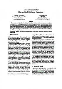
In the above code, the computation proceeds as follows. In first three lines, the SDP connects with each processor through the crossbar and writes the column (one word at a time) on the output port. That column is input by the corresponding processor. In statement 5, the SDP connects with all the processors in a broadcast mode. Then from statement 6 onwards, the SDP broadcasts the data from matrix A in row major order and each processor computes the inner product with each row. Finally, each processor has a column of the output matrix. It should be mentioned that the above code describes the operation in principle, and does not give exact timing of operations. 2) Systolic Mode: The same computation can be performed in systolic mode. Fig. 3 illustrates a linear systolic configuration of a cluster. The SDP can reconfigure the cluster in a circular linear array after distributing columns of matrix B to processors as before. The SDP is not shown in the figure. The SDP assigns row Ai of matrix A to processor Pi. Each processor computes the inner product of its row with its column. At the same time, a processor writes the element of the row on the output port. This element of the row is input to the next processor (through the programmed crossbar connections). Therefore, each processor receives the rows of matrix A in a systolic fashion and the computation is performed in a systolic fashion. Note that the computation and communication can be efficiently pipelined. In the code, statements 7-10 illustrate the systolic computation. Each element of the row is used by a processor and immediately written on to the output port. At the same time, the processor receives an element of the row of the previous processor (in the circular linear array) on its input port. Therefore, every P cycles a processor computes a new element of the C matrix.
Systolic Computation SDP 1. FOR i=O to i=P-1 D O 2. connect(SDP,P;) 3. out(column Bi) 4. out(row Ai) 5. END-FOR 6. connect(Pi to Pi+lmodP) 7. 8. 9. 10. 11. -
Pi 1. 2. NO-OP 3. in(column Bi) 4. in(column Ai) 5. 6. cii = 0 7. FOR j=O to j=P-1 D O 8. Cii = cii + aij * bji 9. OUt(Uij)y in(Ui-lj) 10. END-FOR 11. repeat 7-10 for each new row
pk
1. 2. 3. 4. 5. 6. 7. 8.
NO-OP in(column B;) NO-OP c;k = 0 FOR j=O to j=P-1 D O in(aij) 9. Cik = c,k + ~Xij X bjk 10. END-FOR
B. Partitioning and Resource Allocation There are several tasks with vastly different characteristics in a CVS. The required number of processors for each task may be different as well as each task may need a different computational mode and partition. Hence, partitionability and dynamic resource allocation are keys to high performance. Partitionability of interconnection networks has been studied by many researchers [40], [30], [22], [lo], [19]. These approaches are, however, relevant only to systems of tightly
1098
IEEE TRANSACTIONS
I
ON PARALLEL
AND DISTRIBUTED
SYSTEMS,
VOL. 4, NO. 10, OCTOBER
1993
DSP
a) SIMD Mode
e
PO
-
3.
PI
P;
-0
0
pp-1
0 -d
b) Systolic Mode Fig.
3.
An
example
of SIMD
and systolic
coupled processes wherein tasks require specific interconnection patterns. In the above cases, links are reserved for specific point-to-point communication while a process executes. Whenever a new process is instantiated, the required resources should be free and linked together in a specified manner. A partition is, in effect, isolated from the rest of the system. Partitioning in NETRA is achieved as follows. W h e n a task is to be allocated, the set of subtrees of SDP’s is identified such that the required number of PE’s is available at their leaves. One of these subtrees is chosen on the basis of load balancing (discussed later), locality considerations, and characteristics of the task. The chosen SDP represents the root of the control hierarchy for the task. Together with the SDP’s in its subtree, it manages the execution of the task. Once the subtree is chosen, the processes may execute in SIMD, MIMD, or systolic mode when they get to the head of the Ready Queues at the PE’s or clusters. Further, MIMD processes may exhibit widely varying execution times as processing required often depends on input data characteristics. If rigid partitions are used, processors would have to wait until all complete processing before they start executing another task. Finally, locality is maintained within the control hierarchy, which limits the intratask communication to within the subtree. Since all tasks are assigned in this manner, the partitioning is only virtual. The PE’s are not required to be physically isolated from the rest of the system. Therefore, unlike physical partitioning of a network, in the above approach, communication and data exchange is possible between tasks operating in different partitions. For example, suppose there are two tasks in the system executing on different partitions, one working on matching models of objects to the models developed from the image data (a high-level vision task), and the other working on probing the image data to resolve disambiguities (using low-level vision tasks, e.g., Hough transform) [38]. For normal operation both tasks can execute within their respective partitions. But they need to provide feedback to each other as the computation progresses. If partitions are isolated, it will
modes
of computation
in a cluster.
be very difficult to achieve this cross-communication between tasks of two partitions. TRAC architecture provides “shuttlememory” which can be used for such communications [22], [21]. In NETRA, cross-partition communication is provided through shared memory for partitions on different clusters, and through the common data memory if different partitions are on the same cluster. C. Flexible Communication Availability of flexible communication is critical to achieving high performance. For example, when a partition operates in a SIMD mode, there is a need to broadcast the programs. W h e n a partition operates in an MIMD mode, where processors in the partition cooperate in the execution of a task, one or more programs need to be transferred to the local memories of the processors. Performing the above justifies the need for selective broadcast capability. In order to take advantage of spatial parallelism in vision tasks, processors working on neighboring data need to communicate quickly amongst themselves in order to obtain high performance. The programmability and flexibility of the crossbar provides fast local communication. A large number of vision algorithms need a broad range of processor connectivities for efficient execution. These connectivities include arrays, pipelines, several systolic configurations, shuffle-exchanges, cubes, meshes, pyramids etc. Each of these connectivities may perform well for some tasks and badly for others. Therefore, using a crossbar with a selective broadcast capability, any of the above configurations can be achieved, and consequently, optimal performance can be achieved within clusters. The need for global communication is relatively low and infrequent. Global communication is needed for intertask communication in a CVS executing on different clusters. It is also needed to input and output data, to transfer data within subtasks of a task when a task is executed on more than one cluster, and finally, it is needed to load programs. The global communication is performed through the global
CHOUDHARY
et al.: NETRA:
ARCHITECTURE
FOR COMPUTER
VISION
SYSTEMS
1099
ComputeSystem_Load; If
RDOTSDP System-Load = 0; For i = 1 to numzhild(ROfJTSDP) do I* rum-child is the number of children of the RDOTSDP tf Receive Load[child(i)l ; SystemLoad = SystemLoad + Load[child(i)l ; End_For Compute AverageLoad; Broadcast Averagelad; Else If LEAFSDP /GDP associated with one cluster*/ Send ClusterLoad to Parent SDP; Recsive AverageLoad; Else /*Internal SDP*/ Sub-TreeLoad - 0; For i = 1 to num-child(ThisSDP) /* nun-child ia the no. of children of this SDP*/ Receive Load[child(i)] ; Sub-Tree-Load = Sub-TreeLoad + Load[child(i)l ; EndSor Send Sub-TrooJnad to Parent SDP; Receive Averago3.oad; End
ComputeSystem-Load. Fig.
4.
Algorithm
for
periodic
memory using the interconnection network. Global memory is used for coarse-grain communication where data is transferred in blocks as described below. D. Load Balancing and Task Scheduling In NETRA, a hierarchical load balancing scheme is proposed. Here, a “load balancing system” executes on the SDPtree as a hierarchy of identical processes. Two levels of load balancing are employed, namely, global load balancing and local load balancing. Global load balancing aids in partitioning and allocating the resources for tasks as discussed earlier. Local load balancing is used to distribute computations (or data) to processors executing parallel subtasks of a task. Local load balancing is a centralized scheme in which the cluster SDP is responsible for local load balancing. The local load balancing can be either static or dynamic or a combination of both. Using the information from local load balancing and other measures of computations, global load balancing is achieved hierarchically by using the SDP hierarchy. A similar approach has been proposed in [15]. In this scheme, each controller SDP maintains the following. 1) A measure of load on the subtree below it. For example, an average number of processes in the Active Queues of PE’s and cluster in the subtree can serve as the measure. 2) A measure of average load over the entire system. This is computed periodically over the entire tree and broadcast to all the SDP’s. Each SDP sends its measure of load to its parent SDP and the root SDP receives the load information for the entire system. The root SDP then broadcasts the measure of load of the entire system to the SDP’s. The procedure for periodic computation of system load is illustrated in Fig. 4. W h e n a task is to be allocated, these measures can be used to select a subtree for its execution as follows: If any subtree corresponding to the child of the current SDP has an adequate number of processors, then the task
computation
of system
load.
is transferred to a child SDP with the lowest load, else if the current subtree has enough resources and the load is not significantly greater than the average system load, then the task is allocated to the current subtree, else the current SDP transfers the task to the parent SDP. In NETRA, a SDP is not confronted with a large volume of information to schedule a task since it needs to consider the average load on the subtree below it and the overall average load of the system. In systems like PASM, REPLICA or PM4, fragmentation can be minimized only if scheduling is static or done considerably in advance of execution. This is because scheduling would involve global considerations such as partitionability of the network and availability of resources. However, since the scheduler cannot determine in advance, what resources will be available at a later time, processes cannot be easily prescheduled. NETRA allows for easy allocation of dynamically created tasks because they are generated on the basis of load balancing and locality considerations alone. E. Block-Level Data and Control Flow A CVS system consists of a collection of tasks, each of which can be executed in parallel in an SIMD, systolic or MIMD mode over a number of processors. Each task can be considered a functional block. A Functional Block thus corresponds to a block of instructions executed on one or more clusters, copies of which are broadcast to several PE’s to be executed as a set of distributed processes. Similarly, data is also organized as Data Blocks, which represent “units” of data. For example, in a graph matching algorithm, a record containing all the information about one node can be considered a block. Each function block requires one or more input data blocks and produces one or more output data blocks. Tokens are used to specify both function blocks and data blocks. A token is composed of the following fields: < Job ID > < Task ID > < Block Number >
1100
IEEETRANSACTIONS
Since the token corresponding to given tasks will differ in their less significant bits, these bits are used to specify port numbers for the global memory. Blocks corresponding to a task are, thus, uniformly distributed over the global memory, and therefore, can be accessed with minimal conflicts. Processes are explicitly assigned to clusters and PE’s. When a task is to be executed in an SIMD-like mode on a cluster, the corresponding token is sent to the leaf SDP controlling the cluster. For MIMD tasks, tokens are assigned to the individual PE’s. Tokens corresponding to the tasks are, however, transferred only to an Active Queue at the PE or the leaf SDP controlling the cluster. Function blocks are broadcast to the selected PE’s or clusters by parent SDP’s. Simultaneously, requests for input-data-blocks are issued. The tokens are moved to the Ready Queue only after all inputdata-blocks are available at the PE or cluster. An explicit control flow scheme is used here because we believe that at the function level, control flow is simple and data dependencies are easily recognized. An interesting approach is that of combining explicit control flow and block level data flow schemes. The memory can queue requests for “empty” blocks and service them when blocks are “full.” F. Intelligent Memory NETRA requires that a PE or a cluster issue requests for input-data-blocks as soon as a process token enters its Active Queue. The required data may not be available in the global memory at that time. Instead of waiting for the data, the processor should proceed with tasks already in the Ready Queue. Therefore, the memory should be capable of queueing requests and responding when data is available. The scheme employed is similar to the I-structure storage technique used for dataflow computers [2]. Each block has associated with it a jklllempty bit. The bit is set to 1 if the required data has been written into the page and is set to 0 otherwise. When a request is made for the block, this bit is examined. If the block is marked full, the request is serviced; otherwise it is queued. There is a controller on each line called Memory Line Controller (MLC). MLC is responsible for accepting requests, queueing them if required, and selecting them for service when appropriate. For this purpose, the MLC maintains a table containing the following information for each block on the line: < Virtual Address >
Higher order bits of the block are used to index into the table. Lower order bits are used to select the global memory port. G. Distributed Memory Management The task of managing the global memory is distributed over the SDP-tree and the MLC’s. Two factors greatly simplify the memory management task. First, the blocks are distributed over the memory ports by using LSB’s of tokens to select the port. This represents block level interleaving of data. For low-level vision algorithms, where equal blocks of data are assigned to tasks, data blocks corresponding to a task are expected to be similar in size, this distribution is expected
ON PARALLEL
AND
DISTRIBUTED
SYSTEMS,VOL.4,NO.lO,OCTOBER
1993
to be very even. For other tasks such as high-level vision tasks, where the distribution of data sets may not be even, interleaving in the manner described above scatters the data uniformly among memory modules, thereby reducing the correlation in access patterns Second, a large locally managed virtual space is provided at each port. The local controller is free to place a block anywhere in its virtual space. Specifically, blocks corresponding to the same task may be allocated in contiguous virtual space. A request for allocation of storage for data blocks is made by the SDP that initiates a task. When the task is complete, requests for deallocation are made. H. Ability to Tolerate Large Memory Access Latency A large multiprocessor implies that response times to memory requests can be large and variable in a nondeterministic manner due to conflicts. Therefore, it is required that PE’s in such a multiprocessor be able to issue multiple requests in advance and accept responses out of order. NETRA is a multiprogrammed system with a large number of processes active at any time. A process becomes active when a token corresponding to the process is entered into the Active Queue of a PE (MIMD mode) or a cluster (SIMD-like mode). Data requests for the input-data-blocks are immediately issued. When all input-data-blocks are available, it is transferred to the Ready Queue. However, while these requests are being serviced, the PE continues to execute processes already in its Ready Queue. Access to memory for one process is thus overlapped with execution of another. V. PRELIMINARY RESULTS
ON
CLUSTER
PERFORMANCE
In this section we present initial performance results based on the implementation of some algorithms on a cluster simulator. The total processing time for a parallel algorithm consists of the following components: Program load time onto the cluster processors (tpl), data load and partitioning time (tdl), computation time of the divided subtasks on the processors (tcp), which is the sum of the processing time on a processor Pi and intra-cluster communication time (tcomm), and the result report time (&). tdl consists of three components: 1) data read time from the global memory (&) by the cluster SDP, 2) crossbar switch setup time (tsw) and, 3) the data broadcast and distribution time onto the cluster processors (&). The total processing time 7(P) of the parallel algorithm on a P processor cluster is given by 7(P)
= t&d + tdl + t,
+ t,,
(1)
where, tdl = t, + t,, + ttw. If the computation and communication
t cp --
max l