Hindawi Publishing Corporation Advances in Materials Science and Engineering Volume 2016, Article ID 9675604, 9 pages http://dx.doi.org/10.1155/2016/9675604
Research Article On Finite Element Computations of Contact Problems in Micropolar Elasticity Victor A. Eremeyev, Andrzej Skrzat, and Feliks Stachowicz Rzesz´ow University of Technology, Al. Powsta´nc´ow Warszawy 8, 35959 Rzesz´ow, Poland Correspondence should be addressed to Victor A. Eremeyev;
[email protected] Received 22 July 2016; Accepted 27 November 2016 Academic Editor: Ying Wang Copyright © 2016 Victor A. Eremeyev et al. This is an open access article distributed under the Creative Commons Attribution License, which permits unrestricted use, distribution, and reproduction in any medium, provided the original work is properly cited. Within the linear micropolar elasticity we discuss the development of new finite element and its implementation in commercial software. Here we implement the developed 8-node hybrid isoparametric element into ABAQUS and perform solutions of contact problems. We consider the contact of polymeric stamp modelled within the micropolar elasticity with an elastic substrate. The peculiarities of modelling of contact problems with a user defined finite element in ABAQUS are discussed. The provided comparison of solutions obtained within the micropolar and classical elasticity shows the influence of micropolar properties on stress concentration in the vicinity of contact area.
1. Introduction Nowadays the interest grows to further development and application extended models of continuum mechanics in order to model micro- and nanostructured materials with complex inner structure. The basic idea of enhancement of classic Cauchy continuum model is to add additional fields describing additional degrees of freedom into constitutive equations or/and consider higher-order gradients of deformations. Among these generalized models there are the surface elasticity, micropolar or Cosserat continua, microstretched and micromorphic media, media with internal variables, gradient elasticity, and so forth. In particular, the micropolar model [1–3] proposed by Cosserat brothers more than hundred years ago found applications for modelling such materials as porous solids [4, 5], bones [6– 8], masonries [9, 10], beam lattices [11], and other composite materials; see [1, 12–15] and reference therein. The micropolar elasticity possesses the description of size-effects and may be useful for description of the microstructured solids such as foam, bones, powders, and soils. In particular, the influence of micropolar properties may be important for the analysis of the stress concentration near holes and
notches or in the vicinity of contact area. Within the Cosserat continuum model the translations and rotations determine the kinematics of the medium and the stress and couple stress tensors are introduced. The micropolar properties of material may be important near singularities or to describe observed experimentally size-effect [16–19]. Let us also note that for such complex media even more general models of continuum mechanics such as gradient elasticity may be useful; see, for example, [20–24]. Application of extended models of continuum for modelling of such structures as open-cell foams, beam lattices, and pantographic systems is motivated by their complex inner structure. For example, in the classic beam theory moments play an important role and their influence is inherited by the homogenized models. Let us also note that for structured and nonhomogeneous beams used as structural elements for foam or lattice description some extended models were proposed in [25–31]. For rods and beams there are some phenomena as warping of crosssection, instabilities, and sensibility to imperfections are also important; see, for example, [32–41]. Considering all of these phenomena may lead to rather complex models of homogenized media. From this point of view the micropolar elasticity may be treated as first step towards modelling of
2
Advances in Materials Science and Engineering
microstructured materials and their contact. Further extensions of the indentation problems can be performed based on the other enriched models of continuum; see, for example, strain gradients models [42, 43]. Let us note that the effective solution of boundary value problems of micropolar elasticity as well as of other enhanced models requires advanced numerical code such as the finite element method. The generalized models of continua require usually more computational efforts than the classical elasticity since there exist more degrees of freedom. For the micropolar continuum we use an isogeometric analysis [44, 45] as efficient FEM strategy which together with a hybrid mixed formulation was applied for generalized continua and structures; see, for example, [46–50]. For the moment commercial FEM software gives one the possibility to use user defined elements and user defined procedure for implementation of nonstandard material models. Here we developed new finite element and implement it in ABAQUS. The paper is organized as follows. In Section 2 we present the basic equations of the linear micropolar elasticity. The equilibrium equations, static and kinematic boundary conditions, and constitutive equations are given. Here we are restricted by isotropic case using the Voigt notation. In Section 3 we discuss the finite element modelling for the micropolar solids. Finally, in Section 4 we present the solution of contact problem for micropolar parabolic stamp and an elastic thick plate.
where 𝑛𝑖 is the unit vector of external normal to the boundary 𝐴 = 𝐴 𝑡 ∪ 𝐴 𝑢 , 𝜑𝑗 and 𝜂𝑗 are external forces and couples, and 𝑢𝑖0 and 𝜃𝑖0 are given on 𝐴 𝑢 surface fields of translations and rotations, respectively. Obviously, other mixed boundary conditions can be introduced. In what follows we are restricting ourselves by isotropic case. For a linear isotropic micropolar solid the constitutive equations are 𝑡𝑖𝑗 = 𝜆𝜀𝑘𝑘 𝛿𝑖𝑗 + (𝜇 + 𝜅) 𝜀𝑖𝑗 + 𝜇𝜀𝑗𝑖 ,
(3)
𝑚𝑖𝑗 = 𝛼𝜅𝑘𝑘 𝛿𝑖𝑗 + 𝛽𝜅𝑗𝑖 + 𝛾𝜅𝑖𝑗 ,
where 𝛿𝑖𝑗 is the Kronecker symbol, and 𝜆, 𝜇, 𝜅, 𝛼, 𝛽, and 𝛾 are the elastic moduli. In (3) we also introduced the stretch tensor 𝜀𝑖𝑗 and the wryness tensor 𝜅𝑖𝑗 given by formulas 𝜀𝑖𝑗 = 𝑢𝑗,𝑖 − 𝑒𝑖𝑗𝑛 𝜃𝑛 ,
(4)
𝜅𝑖𝑗 = 𝜃𝑗,𝑖 .
Using the Voigt notation modified for the micropolar elasticity and introducing the stress and moment stress vectors with stretch and wryness vectors by the formulas
2. Basic Equations of the Micropolar Elasticity Following [1–3] we recall here the basic equations of the linear micropolar elasticity of isotropic solids. The kinematic of a micropolar solid is described by two fields, that is, the field of translations 𝑢𝑖 and the field of rotations 𝜃𝑖 . The latter is responsible for the description of moment interactions of the material particles. Hereinafter the Latin indices take on value 1, 2, or 3 and we use the Einstein summation rule over repeating indices. The equilibrium equations take the form 𝑡𝑖𝑗,𝑖 + 𝑓𝑗 = 0, 𝑚𝑖𝑗,𝑖 + 𝑒𝑗𝑚𝑛 𝑡𝑚𝑛 + 𝑐𝑗 = 0,
(1)
where 𝑡𝑖𝑗 and 𝑚𝑖𝑗 are the stress and couple stress tensors, respectively, 𝑒𝑖𝑗𝑘 is the Levi-Civita third-order tensor, and 𝑓𝑗 and 𝑐𝑖 are external forces and couples. Unlike in classical (Cauchy-type) continua, the tensors 𝑡𝑖𝑗 and 𝑚𝑖𝑗 are not symmetric. Equations (1) constitute the local balance of momentum and moment of momentum, respectively. The static and kinematic boundary conditions have the following form: 𝑛𝑖 𝑡𝑖𝑗 𝐴 = 𝜑𝑗 , 𝑡 𝑛𝑖 𝑚𝑖𝑗 𝐴 = 𝜂𝑗 , 𝑡 (2) 𝑢𝑖 𝐴 𝑢 = 𝑢𝑖0 , 𝜃𝑖 𝐴 𝑢 = 𝜃𝑖0 ,
𝑇
{T} = {𝑡11 , 𝑡22 , 𝑡33 , 𝑡12 , 𝑡21 , 𝑡23 , 𝑡32 , 𝑡13 , 𝑡31 } , 𝑇
{M} = {𝑚11 , 𝑚22 , 𝑚33 , 𝑚12 , 𝑚21 , 𝑚23 , 𝑚32 , 𝑚13 , 𝑚31 } , 𝑇
(5)
{E} = {𝜀11 , 𝜀22 , 𝜀33 , 𝜀12 , 𝜀21 , 𝜀23 , 𝜀32 , 𝜀13 , 𝜀31 } , 𝑇
{K} = {𝜅11 , 𝜅22 , 𝜅33 , 𝜅12 , 𝜅21 , 𝜅23 , 𝜅32 , 𝜅13 , 𝜅31 } , we represent the constitutive equations in the following unified form: {𝜎𝑀} = [C] {𝜀𝑀} , A 0 ), [C] = ( 0 B T {𝜎𝑀} = { } , M
(6)
E {𝜀𝑀} = { } K with 18 × 18 symmetric stiffness matrix [C], where A and B are three-diagonal symmetric 9 × 9 matrices given by
Advances in Materials Science and Engineering
( ( ( ( ( ( [A] = ( ( ( ( ( ( ( (
3
𝜆 + 2𝜇 + 𝜅
𝜆
𝜆
0
0
0
0
0
0
𝜆
𝜆 + 2𝜇 + 𝜅
𝜆
0
0
0
0
0
0
𝜆
𝜆
𝜆 + 2𝜇 + 𝜅
0
0
0
0
0
0
0
0
𝜇+𝜅
𝜇
0
0
0
0
0
0
𝜇
𝜇+𝜅
0
0
0
0
0
0
0
0
𝜇+𝜅
𝜇
0
0
0
0
0
0
𝜇
𝜇+𝜅
0
0
0
0
0
0
0
0
𝜇+𝜅
0
0
0
0
0
0
0
𝜇
𝛼
𝛼
0 0 0 0 0 0
𝛼
𝛼+𝛽+𝛾
𝛼
0 0 0 0 0 0
𝛼
𝛼
0
0
0
0
0
0
0
0
0
0
0
0 0 0 0 𝛾 𝛽
0
0
0
0 0 0 0 𝛽 𝛾)
( ( ( ( ( ( = [B] ( ( ( ( ( ( (
𝛼+𝛽+𝛾
(
𝜇 𝜇 + 𝜅)
(7)
𝛼 + 𝛽 + 𝛾 0 0 0 0 0 0) ) ) 0 𝛾 𝛽 0 0 0 0) ) ) 0 𝛽 𝛾 0 0 0 0) ). ) 0 0 0 𝛾 𝛽 0 0) ) ) 0 0 0 𝛽 𝛾 0 0)
Unlike classical elasticity where the stiffness matrix in the Voigt notations is a symmetric 6 × 6 matrix here we have larger matrices. The values of used micropolar elastic moduli can be found from direct experiments provided in [4, 5, 8, 14] or using homogenization technique [6, 7, 9–11, 51]. Let us note that the homogeneous micropolar model can be derived on the base of the passage from heterogeneous classical (Cauchy) continuum and on using passage from inhomogeneous micropolar (Cosserat) material; see [52– 55]. Analysis of general constitutive equations of anisotropic micropolar solids on the base of the material symmetry groups is performed in [2, 56, 57]. From the experimental point of view it is better to use another set of material parameters [4, 5, 8, 14] listed in Table 1. The boundary value problems of the micropolar isotropic elasticity contain also the boundary value problems of classical elasticity as a special case. This coincidence may be used for verification of the developed code. The first way to reduce the problem is to assume 𝜅 = 0 or 𝑁 = 0. Indeed, if the coupling modulus 𝜅 = 0 the stress tensor becomes symmetric and takes the form 𝑡𝑖𝑗 = 𝜆𝑢𝑘,𝑘 𝛿𝑖𝑗 + 𝜇 (𝑢𝑖,𝑗 + 𝑢𝑗,𝑖 ) .
0 ) ) ) 0 ) ) ) 0 ) ), ) 0 ) ) ) 0 )
(8)
Thus, (1)1 transforms to the classic equilibrium equation of the linear elasticity which is independent of rotations whereas (1)2 includes only rotations. Let us also note that (1)2 has similar form to (1)1 but with different elastic moduli. So in this case the problem is decoupled and translations can be determined independently of microrotations.
The second reduction is possible if one assumes the microrotations to be fixed, 𝜃𝑗 = 0. In this case (1)1 again coincides with classic equilibrium equation with Lame’s moduli 𝜆 and 𝜇. In what follows we use both methods for verification and validation of the developed code.
3. Implementation of Micropolar Elasticity into FEM Software Efficient solution of large boundary value problems requires application of an advanced software. In this research ABAQUS commercial program has been extended by the implementation of the user element (UEL) to solve the micropolar elasticity problems. Special code written in Fortran is linked with ABAQUS software allowing the user to practice all the ABAQUS features without paying an attention to their numerical implementation. From the practical point of view the most important features are creation of sophisticated geometry, application of loads and boundary conditions, applications of constrains and contact conditions, generation of 3D meshes, using the material library, and, the most important feature, being very effective solver. During the solver execution UEL procedure is called twice for each Gaussian point in every element. In the first call the element stiffness should be provided by UEL procedure. Very often user element procedure requires calling UELMAT code (user material procedure) necessary to obtain the relation between stress and strain increments. Another call
4
Advances in Materials Science and Engineering
of UEL procedure is necessary to compute residual forces, element nodal forces resulting from element stresses, which is essential in the convergence monitoring during solving nonlinear problems. Designing of own finite elements is an ambiguous task recommended to advanced users only. It should be mentioned that UEL procedures should be very carefully tested and validated. There are some important disadvantages of using user elements in ABAQUS program. First of all, ABAQUS does not recognize the shape of the element; the element is represented by the set of nodes only. For example, 2D four nodes’ element can be defined as a truss structure, as a frame made up of beams, or as a quadrilateral flat element. In each of the mentioned cases different type of loads can be applied; for example, the pressure can be applied to quadrilateral element only, the bending moment can be applied to beam, and so forth. The visualization of obtained results is another matter. The visualization is not possible without detailed description of an element topology; the set of nodes does not provide this information. That is why only nodal displacements of the user elements can be displayed in ABAQUS postprocessor. Displaying strains and stresses requires developing own graphical programs or using uncomfortable techniques with “ghost” meshes made of ordinary ABAQUS elements constrained to meshes consisting of user elements. The typical call of UEL procedure is presented below:
3 predef, npredf, lflags, mlvarx, ddlmag, mdload, pnewdt, 4 jprops, njpro, period, materiallib) The most important parameters are amatrx (element stiffness matrix) and rhs (right-hand side vector of residuals necessary to check the convergence of computation). In the most simple case of static linear analysis the rhs parameter can be omitted because the convergence (equilibrium equations at nodes) is achieved in the first iteration. The meaning of other parameters is described in ABAQUS documentation. UEL procedure can be slightly simplified if it contains constitutive properties; the call of UELMAT procedure is not necessary, therefore. The whole procedure is typical for the isoparametric finite element formulation in 3D problems with the exception of considered degrees of freedom (in micropolar elasticity there are three displacement components and additionally three microrotations) and strain and stress measures (strain and stress tensors contain more components and are not symmetric). In UEL implementation of micropolar elasticity the same shape functions are used for displacement and microrotations 1 (9) (1 + 𝜉𝜉𝑖 ) (1 + 𝜂𝜂𝑖 ) (1 + 𝜁𝜁𝑖 ) , 8 where 𝜉𝑖 , 𝜂𝑖 , and 𝜁𝑖 are the nodal coordinates in the local coordinate system. For the Eringen strain measure the matrix of the shape functions derivatives is 𝑁𝑖 (𝜉, 𝜂, 𝜁) =
subroutine uelmat (rhs, amatrx, svars, energy, ndofel, nrhs, nsvars, 1 props, nprops, coords, mcrd, nnode, u, du, v, a, jtype, time, 0 𝜀11 } 𝑓1,1 0 { { } { } { } { 0 𝑓1,2 0 𝜀22 } { } { } { } { } ( { } 0 0 𝑓1,3 { { 𝜀33 } } ( { } ( { } { } ( { 𝜀12 } } ( 0 𝑓1,1 0 { { } { } ( { } { } (𝑓 { 𝜀 0 { } ( 1,2 0 21 } { } { { } } ( { } ( 𝜀23 } 0 𝑓1,2 { { } ( 0 { } { } ( { } { ( 𝜀32 } { } { } ( 0 𝑓1,3 0 { { } } ( { } { 𝜀 } ( 0 0 𝑓1,1 { { 13 } } ( { } { } ( { 0 { 𝜀31 } } (𝑓1,3 0 =( { } ( { 𝜅11 } 0 0 { } ( 0 { } { } ( { } {𝜅 } } ( 0 { 0 0 { ( 22 } { } { } ( { } { } ( 𝜅33 } 0 0 { { } ( 0 { } { } ( { } { } ( 𝜅 } ( 0 0 0 { { { 12 } } ( { } { } { ( 0 𝜅21 } 0 0 { } { } ( { } { } ( { } 0 0 𝜅23 } { ( 0 { } { } ( { } { } ( { 𝜅32 } 0 0 { } { } ( 0 { { } } { } { 𝜅13 } 0 0 0 { } { { } } 0 0 {𝜅31 } ( 0
2 dtime, kstep, kinc, jelem, params, ndload, jdltyp, adlmag,
0
0
0
⋅ ⋅ ⋅ 𝑓8,1
0
0
0
0
0
0
0
0
⋅⋅⋅
0
𝑓8,2
0
0
0
0
0
0
0
⋅⋅⋅
0
0
𝑓8,3
0
0
0
0
𝑓1 ⋅ ⋅ ⋅
0
𝑓8,1
0
0
0
−𝑓1 ⋅ ⋅ ⋅ 𝑓8,2
0
0
𝑓1
0
0
⋅⋅⋅
0
0
𝑓8,2
−𝑓1
0
0
⋅⋅⋅
0
𝑓8,3
0
0
−𝑓1
0
⋅⋅⋅
0
0
𝑓8,1
0
𝑓1
0
⋅ ⋅ ⋅ 𝑓8,3
0
0
𝑓1,1
0
0
⋅⋅⋅
0
0
0
0
𝑓1,2
0
⋅⋅⋅
0
0
0
0
0
𝑓1,3 ⋅ ⋅ ⋅
0
0
0
𝑓1,2
0
0
⋅⋅⋅
0
0
0
0
𝑓1,1
0
⋅⋅⋅
0
0
0
0
𝑓1,3
0
⋅⋅⋅
0
0
0
0
0
𝑓1,2 ⋅ ⋅ ⋅
0
0
0
𝑓1,3
0
⋅⋅⋅
0
0
0
0
0
𝑓1,1 ⋅ ⋅ ⋅
0
0
0
0
) 0 ) {𝑢11 } } ){ { } { 1} } 0 0 𝑓8 ) ){ { 𝑢 } 2} } ){ { } { } ) { 1 0 0 −𝑓8 ) { } {𝑢3 } } { } ){ } { { 1} 𝑓8 0 0 ) } { 𝜃 ){ 1} } } ){ { { } { 1} −𝑓8 0 0 ) } 𝜃 } ){ { } ){ { 2} } { } 0 −𝑓8 0 ) { 1 𝜃3 } } ){ { } { } ){ 0 𝑓8 0 ) { } {.} ) . , . } ) { } 𝑓8,1 0 0 ){ { } { 8} } ){ { } {𝑢1 } } 0 𝑓8,2 0 ) } ){ { } ){ { 8} } { 𝑢 ) { 0 0 𝑓8,3 ) { } { 2} } } { ){ 8} } { 𝑢 ) { 𝑓8,2 0 0 ){ 3} } { } } } ){ { 8 } {𝜃1 } 0 𝑓8,1 0 ) { } { } ){ } ){ {𝜃8 } } { 0 𝑓8,3 0 ) { 2} } } ){ { { 8} 0 0 𝑓8,2 ) ) {𝜃3 } 𝑓8,3 0 0 0
0
𝑓8,1 )
(10)
Advances in Materials Science and Engineering
5
Table 1: Micropolar material parameters. Description
Symbol
Shear modulus [MPa]
𝐺
Poisson’s ratio [—]
]
Coupling number [—]
𝑁
Characteristic length (torsion) [m]
𝑙𝑡
Characteristic length (bending) [m]
𝑙𝑏
Polar ratio [—]
Ψ
𝑗
Formula 2𝜇 + 𝜅 𝐺= 2 𝜆 ]= 2𝜆 + 2𝜇 + 𝜅 𝜅 𝑁2 = 2(𝜇 + 𝜅) 𝛽+𝛾 𝑙𝑡 = 2𝜇 + 𝜅 𝛾 𝑙𝑏 = 2𝜇 + 𝜅 𝛽+𝛾 Ψ= 𝛼+𝛽+𝛾
𝑗
where 𝑢𝑖 and 𝜃𝑖 are the 𝑖th displacement or microrotation components in the 𝑗th node, respectively. In the isoparametric element the shape functions (9) are applied for the mapping of local coordinates 𝜉, 𝜂, 𝜁 to the coordinates 𝑥, 𝑦, 𝑧 of the global Cartesian coordinate system 𝑥 = ∑ 𝑁𝑖 (𝜉, 𝜂, 𝜁) 𝑥𝑖 ; 𝑦 = ∑ 𝑁𝑖 (𝜉, 𝜂, 𝜁) 𝑦𝑖 ;
(11)
𝑧 = ∑ 𝑁𝑖 (𝜉, 𝜂, 𝜁) 𝑧𝑖 .
𝜉,𝑥 𝜂,𝑥 𝜁,𝑥 {𝑁𝑖,𝜉 } 𝑁𝑖,𝑥 { } } { { } } { 𝑁 𝑁 𝜉 𝜂 𝜁 ) = ( 𝑖,𝜂 𝑖,𝑦 ,𝑦 ,𝑦 ,𝑦 { } } { { } } { { } 𝜉,𝑧 𝜂,𝑧 𝜁,𝑧 {𝑁𝑖,𝜁 } {𝑁𝑖,𝑧 }
(12)
𝑁 𝑁𝑖,𝑥 { { } { 𝑖,𝜉 } } { } } −1 { 𝑁 𝑁 = J , 𝑖,𝜂 𝑖,𝑦 { } { } { } { } { } {𝑁𝑖,𝑧 } {𝑁𝑖,𝜁 }
(13)
or
𝑥,𝜉 𝑦,𝜉 𝑧,𝑥 (14)
𝑥,𝜁 𝑧,𝜁 𝑧,𝜁 which can be found from (9) and (11). The stiffness matrix of developed element is
𝑉
(1) Find the shape functions at each Gaussian point and their derivatives with respect to natural coordinates (2) Find the Jacobian matrix (14); numerically compute its inverse and determinant (3) Find the shape functions derivatives (13) with respect to Cartesian coordinates 𝑥, 𝑦, 𝑧 (4) Find the matrix of shape functions derivatives D (the relation between strain components and nodal displacements and microrotations) (5) Find the constitutive matric C (the relation between stress and strain tensors) (6) Compute D𝑇 CD (for the 2-point Gaussian quadrature all weights are equal to ones) and add it as the contribution to the stiffness matrix which uses the determinant of Jacobian matrix as the multiplier
(1) Find the element nodal forces resulting from element stresses and subtract them from the external nodal forces in order to compute residuals (necessary to check the rate of the solution convergence) (2) Make other computations; for example, update the strain energy
4. Parabolic Stamp Indentation
where J is the Jacobian matrix
K = ∫ D𝑇 CD 𝑑𝑉,
(i) Calculation of stiffness matrix of 8-node isoparametric element for micropolar elasticity. In the loop over the Gaussian points (the are 8 Gaussian points)
(ii) Additional computations
Calculation of derivatives 𝑓𝑖,𝑗 requires application of chain rule; that is,
J = (𝑥,𝜂 𝑦,𝜂 𝑦,𝜂 ) ,
Short description of micropolar elasticity 8-node isoparametric element implementation consists of several steps. The user element procedure based on (9) and (11)–(15) is shortly summarized below.
(15)
where the constitutive stiffness matrix C is presented in the previous section. The integration in (15) is performed as the loop over the Gaussian points. The 2 × 2 × 2 Gaussian quadrature is used.
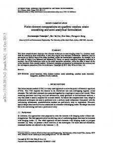
Using the presented above finite element we analyzed few 3D static problems for solids with certain singularities such as notch, hole, or small contact area for the contact problem of two solids [17]. For comparison of solutions with the linear elasticity we used the fact that the micropolar elasticity provides the same solutions as classic elasticity if we assume specific form of microrotations (𝜃𝑖 = 0) or for specific set of elastic moduli that is without coupling (𝜅 = 0). Similar results obtained by the commercial software using the classical theory of elasticity and the results acquired by use of user element while reduced number of material data is used prove that the solution obtained by the UEL procedure is reliable. In this research the Hertzian contact between a parabolic stamp and a half space is considered. For classical Hertz theory of an elastic contact we refer, for example, to [58, pp. 102–14], where formulas for stress distribution are also given. By parabolic stamp we mean a solid with surface in the form of an elliptic paraboloid that is a surface given by equation 𝑝2 𝑦 = 𝑥2 + 𝑧2 , where 𝑝 is a parameter, and 𝑥, 𝑦, and
6
Advances in Materials Science and Engineering y
z
x
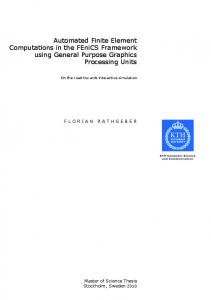
Figure 1: Fine element mesh in the contact problem. S, Mises (Avg: 75%) +4.098e + 06 +3.757e + 06 +3.416e + 06 +3.074e + 06 +2.733e + 06 +2.392e + 06 +2.050e + 06 +1.709e + 06 +1.367e + 06 +1.026e + 06 +6.847e + 05 +3.434e + 05 +2.017e + 03
Figure 2: Von Mises stress [Pa]: commercial software, classical theory of elasticity.
𝑧 are the Cartesian coordinates, respectively; see Figure 1. The main problem arising in this type of analysis is that ABAQUS program does not recognize the volumes and faces of user elements (user element is represented by a set of nodes). The only possible contact formulation is the contact between the surface (ordinary finite elements implemented in ABAQUS) and the set of nodes (UEL elements), therefore. The solution is less precise than the solution of the same problem considering the contact of two surfaces although reasonable results can be achieved for sufficiently dense meshes. The contact of a parabolic stamp made of polystyrene foam with the flat elastic plate is considered. The foam is modelled as a micropolar material. For the foam we use following material data [5]: shear modulus 𝐺 = 104 MPa, Poisson’s ratio ] = 0.4, characteristic length for torsion 𝑙𝑡 = 0.62 mm, characteristic length for bending 𝑙𝑏 = 0.33 mm, coupling number 𝑁 = 0.04, and polar ratio Ψ = 1.5. The average cell size of the foam is about 1 mm; it correlates with characteristic lengths. As in the case of homogenization of regular lattice structures [11], the foam cell size plays a role of a characteristic length parameter, and 𝑙𝑏 and 𝑙𝑡 depend on
it. For the plate we consider the classic elastic material with the same shear modulus and Poisson’s ratio as for foam. In Figure 1 the finite element mesh is presented which is dense enough in the contact zone in order to obtain the results confirming Hertz’s formulas. The distribution of von Mises stress obtained by ABAQUS within classical linear theory of elasticity is shown in Figure 2. Very similar results (distribution and magnitude) are obtained using developed micropolar user elements when microrotations are fixed. This demonstrates excellent convergence of the distribution of stress and stress magnitudes using the developed element to the classical solutions. So the developed UEL procedure is reliable. In Figure 3 the distribution of couple stress 𝑚𝑦𝑦 in the vicinity of the contact zone is shown; here 𝑦 is the vertical axis. Couple stress appears only in the stamp (modelled as the micropolar medium) near the contact zone. As expected the distribution of 𝑚𝑦𝑦 is antisymmetric. The magnitude of couple stress (all components) is several orders smaller than the magnitude of Cauchy stresses. Thus, the influence of the micropolar properties is restricted only to zones
Advances in Materials Science and Engineering
7
References
Figure 3: The distribution of couple stress 𝑚𝑦𝑦 .
with singularities such as sudden change in normal stresses in contact area and free surface. On the other hand, the micropolar elasticity gives the possibility to capture sizeeffect, observed for microstructured solids such as foams as well as in the case of nanoindentation. All solved benchmark tests for 𝜅 ≠ 0 considered here have shown that the difference between classical elasticity and micropolar one is essential in an area of size of the characteristic length. In such areas the stresses are not symmetric and there is a redistribution of the deformation energy among translational and rotational degrees of freedom; one can expect rotations of microstructural elements such as foam struts in foams or grains in granular media. So for local behavior such as in the case of contact problem with small area and deformations near other types of stress concentrators and at the microand nanoscales the influence of micropolar properties can be important.
5. Conclusions We discussed finite element approach adopted to the linear micropolar elasticity in order to model microstructured solids such as porous materials and beam lattices. The new 8-node hybrid micropolar isoparametric element and its implementation in ABAQUS are presented. Here we analyzed the contact problem between two elastic solids. Comparison of solutions based on classical and micropolar elasticity is carefully discussed. Numerical tests have shown that couple stress appears almost in the vicinity of contact zone.
Competing Interests The publication of the paper does not lead to any conflict of interests.
Acknowledgments Authors acknowledge the support by the People Program (Marie Curie ITN transfer) of the European Union’s Seventh Framework Programme for research, technological development, and demonstration under Grant Agreement no. PITNGA-2013-606878.
[1] V. A. Eremeyev, L. P. Lebedev, and H. Altenbach, Foundations of Micropolar Mechanics, Springer Briefs in Applied Sciences and Technology, Springer, Heidelberg, Germany, 2013. [2] A. C. Eringen, Microcontinuum field theories. I. Foundations and solids, Springer, New York, USA, 1999. [3] W. Nowacki, Theory of Asymmetric Elasticity, Pergamon, Oxford, UK, 1986. [4] R. S. Lakes, “Experimental micro mechanics methods for conventional and negative Poisson’s ratio cellular solids as Cosserat continua,” Journal of Engineering Materials and Technology, vol. 113, no. 1, pp. 148–155, 1991. [5] R. S. Lakes, “Experimental microelasticity of two porous solids,” International Journal of Solids and Structures, vol. 22, no. 1, pp. 55–63, 1986. [6] I. Goda, M. Assidi, S. Belouettar, and J. F. Ganghoffer, “A micropolar anisotropic constitutive model of cancellous bone from discrete homogenization,” Journal of the Mechanical Behavior of Biomedical Materials, vol. 16, no. 1, pp. 87–108, 2012. [7] I. Goda and J.-F. Ganghoffer, “Identification of couple-stress moduli of vertebral trabecular bone based on the 3D internal architectures,” Journal of the Mechanical Behavior of Biomedical Materials, vol. 51, pp. 99–118, 2015. [8] J. F. C. Yang and R. S. Lakes, “Experimental study of micropolar and couple stress elasticity in compact bone in bending,” Journal of Biomechanics, vol. 15, no. 2, pp. 91–98, 1982. [9] D. Besdo, “Towards a Cosserat-theory describing motion of an originally rectangular structure of blocks,” Archive of Applied Mechanics, vol. 80, no. 1, pp. 25–45, 2010. [10] P. Trovalusci, M. Ostoja-Starzewski, M. L. De Bellis, and A. Murrali, “Scale-dependent homogenization of random composites as micropolar continua,” European Journal of Mechanics—A/Solids, vol. 49, pp. 396–407, 2015. [11] F. Dos Reis and J. F. Ganghoffer, “Construction of micropolar continua from the asymptotic homogenization of beam lattices,” Computers & Structures, vol. 112-113, pp. 354–363, 2012. [12] H. Altenbach and V. A. Eremeyev, “Strain rate tensors and constitutive equations of inelastic micropolar materials,” International Journal of Plasticity, vol. 63, pp. 3–17, 2014. [13] V. A. Eremeyev, “On effective properties of materials at the nano- and microscales considering surface effects,” Acta Mechanica, vol. 227, no. 1, pp. 29–42, 2016. [14] R. S. Lakes, “Experimental methods for study of Cosserat elastic solids and other generalized continua,” in Continuum Models for Materials with Micro-Structure, H. M¨uhlhaus, Ed., pp. 1–22, John Wiley & Sons, New York, NY, USA, 1995. [15] H. Reda, Y. Rahali, J. F. Ganghoffer, and H. Lakiss, “Wave propagation in 3D viscoelastic auxetic and textile materials by homogenized continuum micropolar models,” Composite Structures, vol. 141, pp. 328–345, 2016. [16] T. Ariman, “On the stresses around a circular hole in micropolar elasticity,” Acta Mechanica, vol. 4, no. 3, pp. 216–229, 1967. [17] V. A. Eremeyev, A. Skrzat, and A. Vinakurava, “Application of the micropolar theory to the strength analysis of bioceramic materials for bone reconstruction,” Strength of Materials, vol. 48, no. 4, pp. 573–582, 2016. [18] P. N. Kaloni and T. Ariman, “Stress concentration effects in micropolar elasticity,” Zeitschrift f¨ur angewandte Mathematik und Physik ZAMP, vol. 18, no. 1, pp. 136–141, 1967.
8 [19] S. H. Salehi and M. Salehi, “Numerical investigation of nanoindentation size effect using micropolar theory,” Acta Mechanica, vol. 225, no. 12, pp. 3365–3376, 2014. [20] F. dell’Isola and D. Steigmann, “A two-dimensional gradientelasticity theory for woven fabrics,” Journal of Elasticity. The Physical and Mathematical Science of Solids, vol. 118, no. 1, pp. 113–125, 2015. [21] F. dell’Isola, I. Giorgio, M. Pawlikowski, and N. L. Rizzi, “Large deformations of planar extensible beams and pantographic lattices: heuristic homogenization, experimental and numerical examples of equilibrium,” Proceedings of the Royal Society of London A: Mathematical, Physical and Engineering Sciences, vol. 472, no. 2185, Article ID 20150790, 2016. [22] F. Dell’Isola, D. Steigmann, and A. Della Corte, “Synthesis of fibrous complex structures: designing microstructure to deliver targeted macroscale response,” Applied Mechanics Reviews, vol. 67, no. 6, Article ID 060804, 21 pages, 2015. [23] D. Scerrato, I. Giorgio, and N. L. Rizzi, “Three-dimensional instabilities of pantographic sheets with parabolic lattices: numerical investigations,” Zeitschrift f¨ur Angewandte Mathematik und Physik, vol. 67, no. 3, article 53, pp. 1–19, 2016. [24] D. Scerrato, I. A. Zhurba Eremeeva, T. Lekszycki, and N. L. Rizzi, “On the effect of shear stiffness on the plane deformation of linear second gradient pantographic sheets,” Zeitschrift f¨ur Angewandte Mathematik und Mechanik, vol. 96, no. 11, pp. 1268– 1279, 2016. [25] H. Altenbach, M. Birsan, and V. A. Eremeyev, “Cosserat-type rods,” in Generalized Continua from the Theory to Engineering Applications, vol. 541 of CISM International Centre for Mechanical Sciences, pp. 179–248, Springer, Vienna, Austria, 2013. [26] H. Aminpour and N. Rizzi, On the Continuum Modelling of Carbon Nano Tubes, vol. 108 of Civil-Comp Proceedings, 2015. [27] H. Aminpour and N. Rizzi, “On the modelling of carbon nano tubes as generalized continua,” in Generalized Continua as Models for Classical and Advanced Materials. Advanced Structured Materials, H. Altenbach and S. Forest, Eds., vol. 42 of Advanced Structured Materials, pp. 15–35, Springer International, Cham, Switzerland, 2016. [28] J. L. Ericksen and C. Truesdell, “Exact theory of stress and strain in rods and shells,” Archive for Rational Mechanics and Analysis, vol. 1, no. 1, pp. 295–323, 1958. [29] A. E. Green and P. M. Naghdi, “Non-isothermal theory of rods, plates and shells,” International Journal of Solids and Structures, vol. 6, no. 2, pp. 209–244, 1970. [30] A. E. Green, P. M. Naghdi, and M. L. Wenner, “On the theory of rods. II. Developments by direct approach,” International Journal of Solids and Structures, vol. 337, no. 1611, pp. 485–507, 1974. [31] M. B. Rubin, Cosserat Theories: Shells, Rods and Points, Kluwer, Dordrecht, The Netherlands, 2000. [32] H. Aminpour and N. Rizzi, “A one-dimensional continuum with microstructure for single-wall carbon nanotubes bifurcation analysis,” Mathematics and Mechanics of Solids, vol. 21, no. 2, pp. 168–181, 2016. [33] H. Aminpour, N. Rizzi, and G. Salerno, “A one-dimensional beam model for single-wall carbon nano tube column buckling,” in Proceedings of the 12th International Conference on Computational Structures Technology, Stirlingshire, UK, September 2014. [34] M. Bˆırsan, H. Altenbach, T. Sadowski, V. A. Eremeyev, and D. Pietras, “Deformation analysis of functionally graded beams by
Advances in Materials Science and Engineering
[35]
[36]
[37]
[38]
[39] [40]
[41]
[42] [43]
[44]
[45]
[46]
[47]
[48]
[49]
[50]
[51]
the direct approach,” Composites Part B: Engineering, vol. 43, no. 3, pp. 1315–1328, 2012. S. Gabriele, N. Rizzi, and V. Varano, “On the imperfection sensitivity of thin-walled frames,” in Proceedings of the 11th International Conference on Computational Structures Technology, B. H. V. Topping, Ed., vol. 99, Civil-Comp Press, 2012. S. Gabriele, N. Rizzi, and V. Varano, “A 1D nonlinear TWB model accounting for in plane cross-section deformation,” International Journal of Solids and Structures, vol. 94-95, pp. 170–178, 2016. S. Gabriele, N. L. Rizzi, and V. Varano, “A one-dimensional nonlinear thin walled beam model derived from koiter shell theory,” in Civil-Comp Proceedings, vol. 106, 2014. D. H. Hodges, Nonlinear Composite Beam Theory, vol. 213 of Progress in Astronautics and Aeronautics, American Institute of Aeronautics and Astronautics, Reston, Va, USA, 2006. D. Iesan, Classical and Generalized Models of Elastic Rods, CRC Press, Boca Raton, Fla, USA, 2009. M. Pignataro, G. Ruta, N. Rizzi, and V. Varano, “Effects of warping constraints and lateral restraint on the buckling of thin-walled frames,” in Proceedings of the ASME International Mechanical Engineering Congress and Exposition (IMECE ’09), pp. 803–810, Lake Buena Vista, Fla, USA, November 2009. N. L. Rizzi and V. Varano, “On the post buckling analysis of thin-walled frames,” in Proceedings of the 13th International Conference on Civil, Structural and Environmental Engineering Computing, CC 2011, Lecture Notes in Computer Science, p. 14, Springer, Chania, Greece, 2011. E. C. Aifantis, “Update on a class of gradient theories,” Mechanics of Materials, vol. 35, no. 3–6, pp. 259–280, 2003. D. C. C. Lam, F. Yang, A. C. M. Chong, J. Wang, and P. Tong, “Experiments and theory in strain gradient elasticity,” Journal of the Mechanics and Physics of Solids, vol. 51, no. 8, pp. 1477– 1508, 2003. J. A. Cottrell, T. J. R. Hughes, and Y. Bazilevs, Isogeometric Analysis: Toward Integration of CAD and FEA, John Wiley & Sons, Chichester, UK, 2009. T. J. Hughes, J. A. Cottrell, and Y. Bazilevs, “Isogeometric analysis: CAD, finite elements, NURBS, exact geometry and mesh refinement,” Computer Methods in Applied Mechanics and Engineering, vol. 194, no. 39–41, pp. 4135–4195, 2005. R. De Borst, L. J. Sluys, H.-B. M¨uhlhaus, and J. Pamin, “Fundamental issues in finite element analyses of localization of deformation,” Engineering Computations, vol. 10, no. 2, pp. 99–121, 1993. P. Fischer, M. Klassen, J. Mergheim, P. Steinmann, and R. M¨uller, “Isogeometric analysis of 2D gradient elasticity,” Computational Mechanics, vol. 47, no. 3, pp. 325–334, 2011. H. G´omez, V. M. Calo, Y. Bazilevs, and T. J. Hughes, “Isogeometric analysis of the Cahn-Hilliard phase-field model,” Computer Methods in Applied Mechanics and Engineering, vol. 197, no. 4950, pp. 4333–4352, 2008. L. Greco and M. Cuomo, “An isogeometric implicit G1 mixed finite element for Kirchhoff space rods,” Computer Methods in Applied Mechanics and Engineering, vol. 298, pp. 325–349, 2016. L. Placidi, “A variational approach for a nonlinear 1-dimensional second gradient continuum damage model,” Continuum Mechanics and Thermodynamics, vol. 27, no. 4-5, pp. 623–638, 2015. D. Bigoni and W. J. Drugan, “Analytical derivation of Cosserat moduli via homogenization of heterogeneous elastic materials,”
Advances in Materials Science and Engineering
[52]
[53]
[54] [55]
[56]
[57]
[58]
American Society of Mechanical Engineers. Transactions of the ASME. Journal of Applied Mechanics, vol. 74, no. 4, pp. 741–753, 2007. G. Hu, X. Liu, and T. J. Lu, “A variational method for non-linear micropolar composites,” Mechanics of Materials, vol. 37, no. 4, pp. 407–425, 2005. R. Larsson and S. Diebels, “A second-order homogenization procedure for multi-scale analysis based on micropolar kinematics,” International Journal for Numerical Methods in Engineering, vol. 69, no. 12, pp. 2485–2512, 2007. Q. Liu, “A new version of Hill’s lemma for Cosserat continuum,” Archive of Applied Mechanics, vol. 85, no. 6, pp. 761–773, 2015. P. Sharma and A. Dasgupta, “Average elastic fields and scale-dependent overall properties of heterogeneous micropolar materials containing spherical and cylindrical inhomogeneities,” Physical Review B, vol. 66, no. 22, Article ID 224110, 2002. V. A. Eremeyev and W. Pietraszkiewicz, “Material symmetry group of the non-linear polar-elastic continuum,” International Journal of Solids and Structures, vol. 49, no. 14, pp. 1993–2005, 2012. V. A. Eremeyev and W. Pietraszkiewicz, “Material symmetry group and constitutive equations of micropolar anisotropic elastic solids,” Mathematics and Mechanics of Solids, vol. 21, no. 2, pp. 210–221, 2016. K. L. Johnson, Contact Mecanics , Cambridge University Press, Cambridge, UK, 1985.
9
Journal of
Nanotechnology Hindawi Publishing Corporation http://www.hindawi.com
Volume 2014
International Journal of
International Journal of
Corrosion Hindawi Publishing Corporation http://www.hindawi.com
Polymer Science Volume 2014
Hindawi Publishing Corporation http://www.hindawi.com
Volume 2014
Smart Materials Research Hindawi Publishing Corporation http://www.hindawi.com
Journal of
Composites Volume 2014
Hindawi Publishing Corporation http://www.hindawi.com
Volume 2014
Journal of
Metallurgy
BioMed Research International Hindawi Publishing Corporation http://www.hindawi.com
Volume 2014
Nanomaterials
Hindawi Publishing Corporation http://www.hindawi.com
Volume 2014
Submit your manuscripts at http://www.hindawi.com Journal of
Materials Hindawi Publishing Corporation http://www.hindawi.com
Volume 2014
Journal of
Nanoparticles Hindawi Publishing Corporation http://www.hindawi.com
Volume 2014
Nanomaterials Journal of
Advances in
Materials Science and Engineering Hindawi Publishing Corporation http://www.hindawi.com
Volume 2014
Journal of
Hindawi Publishing Corporation http://www.hindawi.com
Volume 2014
Journal of
Nanoscience Hindawi Publishing Corporation http://www.hindawi.com
Scientifica
Hindawi Publishing Corporation http://www.hindawi.com
Volume 2014
Journal of
Coatings Volume 2014
Hindawi Publishing Corporation http://www.hindawi.com
Crystallography Volume 2014
Hindawi Publishing Corporation http://www.hindawi.com
Volume 2014
The Scientific World Journal Hindawi Publishing Corporation http://www.hindawi.com
Volume 2014
Hindawi Publishing Corporation http://www.hindawi.com
Volume 2014
Journal of
Journal of
Textiles
Ceramics Hindawi Publishing Corporation http://www.hindawi.com
International Journal of
Biomaterials
Volume 2014
Hindawi Publishing Corporation http://www.hindawi.com
Volume 2014