Using a Tightly-Coupled Pipeline in Dynamically Reconfigurable Platform FPGAs∗ Miguel L. Silva FEUP/DEEC Rua Dr. Roberto Frias, s/n 4200-465 PORTO, Portugal
[email protected]
João Canas Ferreira FEUP/DEEC and INESC Porto Rua Dr. Roberto Frias, s/n 4200-465 PORTO, Portugal
[email protected]
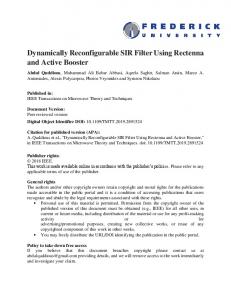
Abstract The paper describes the organization and use of a pipeline that is tightly-coupled to the CPU inside a platform FPGA with support for dynamic partial reconfiguration. It describes the overall hardware system organization and the pipeline structure, and presents the associated development environment and run-time support system, including the support for dynamically changing pipeline implementations and altering the operations of a pipeline stage. Figure 1. Pipeline for pattern matching.
1. Introduction Current high-end field-programmable gate arrays (FPGAs), like the Virtex-II Pro from Xilinx [3], combine the traditional fabric (based on configurable logic blocks and configurable interconnect) with complex blocks like embedded processor cores, dedicated multipliers, RAM blocks and digital clock managers, in order to provide a powerful platform for high-performance, scalable systems. Such platform FPGAs are a cost-effective and versatile means to develop and deploy complex stand-alone digital systems. In addition to these capabilities, Virtex-II Pro FPGAs support partial reconfiguration of sections of the logic fabric without upsetting the operation of the remaining FPGA resources. This feature enables the run-time reconfiguration of the logic fabric during application execution. We have been developing a real-time video processing system based around such a platform FPGA. The system is expected to obtain raw color video images at 30 frames/second from a CMOS sensor-based camera and ∗
This work has been partially funded by the Department of Electrical and Computer Engineering of the Faculty of Engineering of the University of Porto (FEUP), under contract DEEC-ID/05/2003.
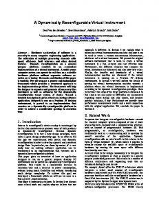
to process them in order to obtain different types of information of interest while producing a VGA-compatible video output. In this context, we have been led to consider the implementation of simple, dynamically reconfigurable pipelines for data processing. Each instance of the pipeline performs a series of basic operations. A controlling program runs on the embedded CPU and switches pipeline instances when necessary by dynamically reconfiguring the area where the pipeline is implemented. In the current implementation, the controlling program is responsible for transferring the data to/from the pipeline; future versions may acquire data directly from external sources. To make this discussion more concrete, figure 1 shows a block diagram of the pipeline as used in a simple pattern matching application. The first stage interfaces to the data bus and generates the enable signal for the entire pipeline. Each write operation to the pipeline makes the pipeline advance by one step. This mode of operation is not specific to this application; many pipelines can use such a setup. Figure 2 shows samples of the different types of blocks used in this example. The input data is 19 bits wide: 16 data bits plus a 3-bit counter value. As the data flows through
Figure 3. Overview of the system setup. Figure 2. Blocks for the pipeline (examples). the pipeline, the 16 data bits are compared to some predefined patterns (encoded in the comparison logic); whenever there is a match, the counter value is incremented. The last pipeline stage determines a 1-bit pass/fail result by comparing the counter value to a fixed threshold. The use of fixed patterns in the comparisons or the use of a constant threshold value does not limit the design. A set of pipelines with different patterns and threshold values can be created off-line; the application needs only to switch among them at runtime. The pipelines are built by combining the partial bitstream of the individual stages. In some applications, constant data can be encoded in the logic functions of the pipeline (the A block of figure 2 in the example). In the Virtex-II Pro architecture (like in other Xilinx FPGA families), the logic functions’ implementation is based on look-up tables. By changing the contents of the look-up tables, the logic function can be changed. Our runtime system includes support for this kind of operation. Although we have illustrated the pipeline operation with very simple stages, our development and run-time systems are relatively general. Currently, the main architectural restriction is the absence of feedback connections between pipeline stages. Note that individual stages may include sequential circuits with internal feedback as long as they do not disrupt the orderly flow of data through the pipeline. Each stage may contribute more than one clock cycle to the pipeline latency, as long as it is capable of providing and accepting new values at each clock cycle. The rest of the paper is organized as follows. Section 2 describes describes the pipeline organization. Section 3 describes the design flow for application development. The run-time support for dynamic reconfiguration and pipeline operation is described in section 4. Section 5 concludes the paper and gives some pointers to further work.
2. Conceptual pipeline organization Conceptually, the reconfigurable fabric of the system is divided in two areas, the static area and the dynamically reconfigurable area. The basic hardware support system, that
remains unchanged during the application’s execution, is placed in the first one. The second area is time-multiplexed among the tightly-coupled pipelines (which are instantiated as needed by the application running on the CPU) via the run-time management system. Communication with the pipeline is provided by a special Bus Macro. The system as described in [1] is implemented on a Xilinx XC2VP7 FPGA, but it can be implemented in other devices of the same family without significant changes. The overall organization of the system is shown in fig. 3. The PowerPC (PPC) 405 communicates with the rest of the system through the 64-bit Processor Local Bus (PLB). Onchip memory access is provided by a PLB Block RAM Controller. To preserve FPGA resources, other peripherals are connected to a slower On-Chip Peripheral Bus (OPB), through an PLB-to-OPB Bridge. The OPB peripheral HWICAP is used to access the active reconfiguration data controlling the reconfigurable fabric. The OPB Dock connects through a Bus Macro [5] to the pipelines in the dynamic area. OPB peripherals are also used to access the external memory, that stores both the reconfiguration data of the pipelines and the application-specific data. The Dock interface provides data connections and transaction control signals, so that pipelines in the dynamic area behave like bus slaves. The run-time system controls the data being sent to or received from the pipeline simply by writing and reading the memory address assigned to the OPB Dock. Each OPB dock has at most 32 input and 32 output connections. We consider three different types of pipeline stages: an input stage, a internal stage and a output stage. An input stage receives data from the base system, optionally performs some operation on the data and sends it to the next stage. An internal stage receives data from the previous stage, performs some operations and then sends the data to the next stage. Finally, the output stage receives data from the previous stage, optionally performs some operation and sends the data to the base system. The pipeline clock and the pipeline enable signal (both used for synchronization of the data transfers between stages) are provided by an external source: the pipeline clock is the clock signal of the OPB and the pipeline enable signal, used as the global flip-flop
enable signal, is generated by the OPB Dock. We used an approach where individual stages are developed independently, so that each stage can be used for building different pipelines. To achieve this, it is necessary to have a common communication architecture for all stages. Some aspects of the communication architecture may change from application to application, in particular the width of the of data to be transfered. There are two types of communication channels that must be considered: one for the communication between the pipeline with the base system, and another for the communication between the stages in the pipeline. These channels may, in general, depend on the architecture of the stages, their type, and their organization. The organization of the stages in the pipeline depends on the number of resources available. In our current implementation the static area occupies the greater part of the FPGA; the dynamic area is 12 CLBs wide by 28 CLBs high, so we use a vertical distribution of the stages. We consider first the communication between the pipeline and the base system. The communication is implemented by a Bus Macro, as mentioned before. On the side of the dynamic area the Bus Macro is integrated in the stages, and on the static area it is connected to the OPB Dock. Since the communication pattern of the three types of stages is not uniform, the configuration of the Bus Macro has to be divided into blocks. There are three kinds of blocks that correspond to the three types of stages. The block height is the same as the height of the corresponding stage. In our implementation the internal stages may be designed to have direct access to the base system through the OPB Dock (see fig. 4). This capability may be used by the stages to output status signals or to receive additional control signals (useful when a single stage supports more than one mode of operation). If the internal stages have direct connections to the base system, the aforementioned size constraints also apply to them. For a given base system design, the OPB Dock is fixed and all the stages must be designed to match the physical distribution of inputs and outputs. This is easiest if the internal stages have no direct connections to the base system at all. If this is not the case, the reuse of stages is simplified by having stages with a few “standard” sizes. We now consider the communication between adjacent pipeline stages. For this case another design macro, called the Inter-Stage Macro, was used. This macro is divided in two different parts, that are implemented in the two connected stages. The communication channel is unidirectional and may transfer up to 8 per CLB column between stages. The Inter-Stage Macro occupies two vertically contiguous CLBs (see fig. 4). The top part of the connection uses only the CLB registers, while the bottom part uses the lookup
Figure 4. Organization of pipeline stages. tables (LUTs). Both structures are connected by prerouted connections. The sending stage includes the part of the Inter-Stage Macro with the registers, and the receiving stage includes the part with the LUTs. The enable port of the registers should be connected to the pipeline enable signal and the clock port to the global clock line used by the OPB. When assembling the pipelines, it is possible that the internal stages are not enough to completely fill the space between the input and output stages. In this case, pass-through stages are used, that implement no logic function but provide a connection between the Inter-Stage Macros.
3. Design flow In this section we describe the information flow for building an application. Figure 5 shows the information flow for the creation all the data. The first step is to specify the base system with help of the Xilinx EDK. VHDL descriptions of the system and the synthesized peripherals are then exported to the Xilinx Integrated Synthesis Environment (ISE) for implementation. The results of this step may be reused for multiple projects. The next step is to add the Bus Macro to the design, in the form of a relatively placed and synthesized design, and connect it to the inputs/outputs of the OPB Dock. The design is then compiled into the FPGA configuration data file (the bitstream file), that is downloaded to the FPGA. The implementation of the pipeline proceeds by first creating and synthesizing a set of modules corresponding to stages for the pipelines with any appropriate tool. We use VHDL descriptions with Xilinx ISE, but other tools can be used. Next, the synthesized stage is encapsulated inside another design and connected to of the Bus Macro and to the Inter-Stage Macro. A bitstream is generated for each design. For assembling the different stages into a pipeline we use BitLinker, a JBits [2] based program we developed. This program collects configuration information from the different stage bitstreams and assembles them into a single bitstream. One
Figure 5. Data creation information flow assembled bitstream is needed for each pipeline configuration. After all pipelines bitstreams have been assembled, we generate the partial reconfiguration files. All partial reconfiguration files have to be transformed into Module-based Partial Reconfiguration (MPR) files, which are used by our run-time system to manage module information (see sec. 4). The files are created by MPRCreator, an application we developed for this purpose. The implementation of the software, is done in the EDK environment [4]. Starting from the EDK project for the base system, the first step is to configure the Xilinx Microkernel. The application can be written in C/C++, and should use the facilities provided by the Module Manager library we developed to handle the dynamic reconfigurable modules. Finally the whole application must be compiled to a downloadable binary file.
4. Run-time support for pipeline use and dynamic reconfiguration For supporting the run-time use of the pipeline and to allow multiple pipelines to be dynamically reconfigured, we developed a run-time support system in the form of a software library (written in C) that must be linked to the final binary file of every application that uses the pipeline infrastructure. An MPR file is used to store information about the configuration of the pipelines to be implemented in the dynamic areas. The file is divided in two blocks, the header block and the configuration data block. The latter contains the partial
reconfiguration information. The header block contains information related to the pipeline implemented by the configuration data. All MPR files are created by MPRCreator. Our run-time library allows an application to: • load or remove pipelines from the dynamic area; • add or remove MPR files from the on-board memory; • transfer data to and from an installed pipeline; • change pre-designated LUTs in a pipeline; • list available pipelines and their properties. Internally, the library includes a data manager, a reconfiguration manager and an input/output manager. The data manager manages the local cache of MPR files. When the system is prepared for execution, a file system image is downloaded to memory. The data manager provides the functions to access the MPR files in this image. The reconfiguration manager provides higher-level functions for performing reconfiguration. It basically encapsulates the use of the Xilinx OPB HWICAP driver, providing the functions necessary for the pipeline reconfiguration and a stable interface against future changes to the driver or hardware. This manager also provides higher-level functions for LUT reconfiguration given the location and data. The input/output manager provides functions to send and receive data to/from the pipeline. These functions transmit data to the correct memory address, based on information contained in the MPR file of the currently active pipeline.
5. Conclusion The paper described the organization of a tightlycoupled pipeline for platform FPGAs with support for partial dynamic reconfiguration and discussed the issues of putting together the pipeline, dynamically changing pipeline implementations and altering the operations of a pipeline stage at run-time. Further work on this subject will address three main issues: i) providing support for feedback connections among pipeline stages; ii) connecting the pipeline to other data sources (particularly, DMA); iii) run-time reconfiguration of whole pipeline stages (not just some lookup-tables), i.e., building the whole pipeline at run-time.
References [1] J. C. Ferreira and M. M. Silva. Run-time reconfiguration support for FPGAs with embedded CPUs: The hardware layer. In The 12th Reconfigurable Architectures Workshop, 2005. [2] S. Guccione, D. Levi, and P. Sundararajan. JBits: Java based interface for reconfigurable computing. In MAPLD’99, 1999. [3] Xilinx. Virtex-II Pro Platform FPGA Handbook, Sept. 2002. [4] Xilinx. Embedded Development Kit Documentation, 2004. [5] Xilinx. Two flows for partial reconfiguration: Module base or small bit manipulations. Application note 290, Sept. 2004.