PHYSICS OF PLASMAS
VOLUME 7, NUMBER 11
NOVEMBER 2000
Magnetized implosions driven by intense ion beams M. M. Baskoa) Gesellschaft fu¨r Schwerionenforschung, Planckstr. 1, D-64291 Darmstadt, Germany
共Received 2 May 2000; accepted 2 August 2000兲 Intense beams of heavy ions, envisaged for the near future at the Institute for Theoretical and Experimental Physics 共Moscow兲 and Gesellschaft fu¨r Schwerionenforschung 共Darmstadt兲, will be well suited for conducting implosion experiments in cylindrical geometry. In such implosions, the initial pressure generated by the direct beam heating can be enhanced by more than a factor of 10. If, in addition, an external magnetic field is introduced, the effect of magnetothermal insulation may allow to reach kilovolt temperatures and significant thermonuclear neutron yields in magnetized implosions driven by the beam heating intensities as low as ⑀˙ ⯝1 TW/g. It is shown how the combined effect of the electrical resistivity and thermal conductivity sets a lower limit on the product UR 共R is the radius, and U is the velocity of an imploding plasma volume兲 as a necessary condition for the regime of self-sustained magnetized implosion 共SSMI兲. The optimal plasma parameters required for initiation of this regime are evaluated. In cylindrical geometry, the threshold for the SSMI regime is determined by the total driver energy deposition per unit areal density of the cylinder, ⫺1 兩 dE b /dz 兩 (kJ cm2/g). The results of one-dimensional magnetohydrodynamic simulations indicate that the advantages of magnetized implosions begin to manifest themselves at a beam energy level of E b ⬇100 kJ. © 2000 American Institute of Physics. 关S1070-664X共00兲01911-X兴
ⲏ0.5– 1 GeV/u) envisaged for the future facilities at the Institute for Theoretical and Experimental Physics 共ITEP兲 in Moscow 共Russia兲1 and at the GSI.2,3 Such ions can be focused on a circular spot of a submillimeter diameter and have a multimillimeter range even in the most dense materials, thus creating a long cylindrical channel of heated matter in a target. As specific examples, we quote the parameters of the TeraWatt Accumulator 共TWAC兲 beam at ITEP,1 N i ⫽1.2⫻1013 ions of 59Co⫹27 with the kinetic energy of E i /A i ⫽0.7 GeV/u and the total beam energy of E b ⬅N i E i ⬇100 kJ, and those of the High-current Accumulator Ring 共HAR兲 proposed for the future GSI synchrotron,3 N i ⫽1012 ions of 131Xe⫹54 with the kinetic energy of E i /A i ⫽1.1 GeV/u and the total beam energy of E b ⬇20 kJ. Within 10% accuracy, these two beams have equal stopping ranges of 具 l 典 i ⬇30 g/cm2 in solid gold, and 具 l 典 i ⬇15 g/cm2 in gaseous 共1 atm兲 deuterium. When we take the corresponding values of the focal spot radius, r foc⫽0.8–1.0 mm for the TWAC beam1 and r foc⫽0.4 mm for the HAR beam,3 we calculate essentially the same value of the specific energy deposition,
I. INTRODUCTION
Once intense beams of heavy ions become available,1–3 they will offer a new way of generating high energy density states in matter. On the one hand, experiments with ion-beam generated plasmas can be considered as a first step toward controlled fusion driven by heavy ion beams. On the other hand, due to special features of the energy deposition mechanism by fast ions, such experiments can make a contribution of their own to fundamental plasma physics research. In the simplest case, a quasicylindrical plasma volume can be created by focusing an ion beam onto a uniform sample. The peak pressure and temperature values that can be attained in this way and the ensuing hydrodynamic motion have been analyzed recently by Tahir et al.4,5 for realistic beam parameters of the heavy ion synchrotron at the Gesellschaft fu¨r Schwerionenforschung 共GSI兲 in Darmstadt 共Germany兲. In such simple experiments, if one aims at matter states with maximum concentration of energy, hydrodynamic expansion plays a negative role by weakening the pressure and temperature peaks in irradiated targets. At the same time, hydrodynamic flow in a converging geometry can be employed to enhance the initial energy concentration created by the beam heating. In this paper we examine the possibility of using cylindrical implosions in combination with the effect of magnetic insulation to achieve maximum possible pressures and temperatures in the compressed plasma column along the target axis. The cylindrical symmetry of hydrodynamic motion arises naturally in experiments with energetic ions (E i /A i
⑀⫽
2 r foc
冏 冏 再
N i dE i dz
⬇
z⫽0
100 kJ/g in gold, 200 kJ/g in deuterium,
共1兲
for both cases. Here E i ⫽E i (z) is the energy of individual ions as a function of the coordinate z along the beam trajectory. Hydrodynamic consistency between the above values of ⑀ and r foc sets a limit on the ion pulse duration t p ⱗ(100 ns)(r foc/1 mm), which agrees reasonably well with the capabilities of the ion bunch compression technique.1–3
a兲
On leave from the Institute for Theoretical and Experimental Physics, Moscow, Russian Federation; electronic mail:
[email protected]
1070-664X/2000/7(11)/4579/11/$17.00
1
4579
© 2000 American Institute of Physics
Downloaded 22 Feb 2002 to 130.183.91.214. Redistribution subject to AIP license or copyright, see http://ojps.aip.org/pop/popcr.jsp
4580
Phys. Plasmas, Vol. 7, No. 11, November 2000
FIG. 1. Schematic view of a cylindrical target for implosion experiments with ion beams. The implosion is driven by an annular beam irradiating a gold liner layer at r foc0 ⬍r⬍r foc .
M. M. Basko
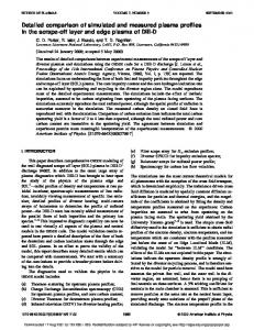
FIG. 2. Pressure and temperature profiles along the trajectory of 1.1 GeV/u Xe ions in three different target materials after a short pulse with the irradiation intensity of 2⫻1014 ions/cm2 .
再冉 1.0
The specific driver energy deposition 共1兲 is used as a reference value in all the hydrodynamic and magnetohydrodynamic 共MHD兲 simulations discussed below. Magnetized cylindrical implosions of hydrogen-isotope plasma columns have been discussed previously in the context of ultrahigh magnetic field generation in gas-puff Z pinches,6,7 and with imploded metallic liners.8 The quality of the magnetic field confinement was characterized by controlling the corresponding magnetic Reynolds values Rm. However, to the author’s knowledge, the parametric analysis of magnetized implosions has never been carried out in such a way as to single out the regime of self-sustained magnetized implosion 共SSMI兲 and to derive the necessary condition 共17兲 for reaching this regime. This latter condition originates from simultaneous constraints on the magnetic Reynolds and the Pe´clet numbers of a magnetized plasma volume compressed by a liner. The SSMI regime is, of course, of critical importance for the concept of magnetized target fusion 共MTF兲, although its comprehensive parametric analysis is missing in the published work on MTF 共see Ref. 9 and references therein兲. The SSMI conditions derived in this paper should provide a useful guidance when one is exploring the large parameter space of the MTF targets.
II. PRESSURE PEAK ENHANCEMENT IN CYLINDRICAL IMPLOSIONS
The imploding configuration that we consider here is shown in Fig. 1. It consists of a metallic tube 共liner兲 filled with a low-density deuterium gas, which is referred to as thermonuclear fuel. The initial inner and outer liner radii are, respectively, R 0 and R l0 . We assume that fast ions propagate along the cylinder axis and heat matter uniformly inside the focal radius r foc during the pulse of duration t p at a constant rate,
⑀˙ ⫽
冉
冊 冊
100 ns tp
100 ns 2.0 tp
TW/g in gold, 共2兲 TW/g in deuterium,
which corresponds to the total energy deposition of ⑀⫽100 kJ/g in gold. To check the uniformity of the ion energy deposition along the cylinder length under realistic experimental conditions, a separate one-dimensional 共1-D兲 run has been performed for stopping of the 1.1 GeV/u Xe ions in the planeparallel geometry. The ion fluence was fixed at a value of 2 ) for N i ⫽1012 and r foc⫽0.4 mm. The pulse duraN i /( r foc tion was set artificially short, t p ⫽0.1 ns, in order to avoid complications due to the hydrodynamic expansion. The resulting temperature and pressure profiles along the ion trajectory at the end of the ion pulse t⫽t p are shown in Fig. 2 for three different target materials. For gold and copper, normal initial densities were assumed, deuterium was simulated at 0 ⫽10⫺3 g/cm3 . Figure 2 demonstrates that the ion energy deposition is uniform to within 10% along the initial 60%–70% of the range, which corresponds to a ⲏ1 cm long cylinder of gold, and to an almost 2 cm long cylinder of copper. The double-hump structure of the Bragg peak in gold and copper is caused by the specific temperature dependence of the ion stopping power in dense plasmas inherent in the stopping model used for the present calculations and discussed in detail in Ref. 10. From this figure one learns also that the highest pressure in static matter is achieved in high-Z materials with the highest initial density. This explains why gold was chosen as the target material for simulations discussed below. In this work we distinguish between two different cases of target irradiation, which correspond to two different implosion patterns. The simplest configuration, referred to as the case of exploding pusher, is realized with a uniform beam profile, when the ion current fills the entire beam cross section at 0⬍r⬍r foc . The gaseous cavity is then imploded by the hot metallic vapor of the unloading inner edge of the
Downloaded 22 Feb 2002 to 130.183.91.214. Redistribution subject to AIP license or copyright, see http://ojps.aip.org/pop/popcr.jsp
Phys. Plasmas, Vol. 7, No. 11, November 2000
Magnetized implosions driven by intense ion beams
C r⫽
FIG. 3. Peak pressure values on the target axis versus ion pulse duration t p . The beam specific energy deposition and its focal radius are fixed, respectively, at ⑀⫽100 kJ/g and r foc⫽0.4 mm. Two implosion configurations 共b兲 and 共c兲 共see the text兲 are compared with the simplest case 共a兲 of solid sample irradiation.
heated liner. The second case of cold pusher requires a hollow 共annular兲 ion beam, which heats the liner material only in the annular region r foc0 ⬍r⬍r foc . Again, we assume that the heating rate in this region is given by Eq. 共2兲. In this case the cavity is imploded by the cold inner portion of the liner originally at R 0 ⬍r⬍r foc0 , which is accelerated inward by heated matter at r foc0 ⬍r⬍r foc . Note that, while the inner, R(t), and the outer, R l (t), edges of the liner move, the boundaries of the energy deposition region, r foc0 and r foc , remain fixed. There may be different methods of creating hollow beams by either an appropriate target design or beam manipulations, but we do not discuss them in this paper. Figure 3 shows the peak pressure values attained on the cylinder axis in 1-D hydrodynamic simulations when the imploding liner is halted by the compressed cavity gas. In these simulations, the focal spot radius was fixed at r foc⫽0.4 mm, while the pulse duration t p was varied. The three cases shown in Fig. 3 have been realized by assigning the following target proportions: 共a兲 solid Au sample: R 0 ⫽r foc0 ⫽0, R l0 ⫽1.5r foc ; 共b兲 exploding Au pusher: r foc0 ⫽0, R 0 ⫽0.7r foc , R l0 ⫽1.5r foc ; and 共c兲 cold Au pusher: R 0 ⫽0.55r foc , r foc0 ⫽0.6r foc , R l0 ⫽1.5r foc . The effect of pressure enhancement due to the hydrodynamic cumulation in the converging flow is demonstrated by comparing the cases 共b兲 and 共c兲 with the reference case 共a兲. First of all note that, if the cavity at r⬍R 0 were void and the imploding liner material obeyed the laws of ideal hydrodynamics, the pressure on the cylinder axis at the time of void closure would be infinite.11 In reality, the central pressure peak is always finite because of the initial gas fill and dissipation processes in the converging flow. Intuitively, it is clear that in the limit of large convergence ratios, C r Ⰷ1, the peak pressure P max must be insensitive to the properties and the initial state of the fill gas: it should be determined solely by the liner configuration, energy deposition in the liner, and the value of C r . Here the radial convergence ratio C r is defined for the gas/metal 共D/Au兲 interface,
R 共 0 兲 ⬅R 0 , R 共 t max兲
4581
共3兲
where t max is the time when the pressure at r⫽0 reaches its peak value P max . The main conclusion from Fig. 3 is that the pressure enhancement factor has modest values of 1.2–1.5 in the case of an exploding pusher, and becomes as high as 10 and larger in the case of a cold pusher. Our simulations indicate also that the peak pressure obtained with the exploding pusher is virtually independent of C r when C r ⬎10; for a cold pusher, on the contrary, it increases noticeably with C r . At this stage, it would be premature to fix any upper limit for realistic values of C r in these types of implosions. Trying not to set unjustified limits, we assume tentatively that any value of C r ⱗ100 might be feasible. When calculating the curves 共b兲 and 共c兲 in Fig. 3, the initial fill gas parameters 0 , T 0 were adjusted such as to keep the C r values in the range 20ⱗC r ⱗ40: 共b兲 0 ⫽3⫻10⫺4 g/cm3 , T 0 ⫽1 eV, full bremsstrahlung and conduction losses; 共c兲 0 ⫽3⫻10⫺4 g/cm3 , T 0 ⫽5 eV, adiabatic compression of the fill gas. With these parameters, the values of C r varied between C r ⫽30 for t p ⫽200 ns and C r ⫽40 for t p ⫽1 ns in case 共b兲, and between C r ⫽24 for t p ⫽200 ns and C r ⫽42 for t p ⫽1 ns in case 共c兲. In view of clear advantages offered by implosions with a cold pusher, we consider only this case in what follows. The geometric target proportions used in all subsequent simulations are those given for the case 共c兲 above. As a precaution against the Rayleigh–Taylor instability at the pusher– absorber interface r⫽r foc0 , the initial aspect ratio of the cold pusher, A p ⫽r foc0 /(r foc0 ⫺R 0 )⫽12, is chosen to be not too high 共for more details see Sec. IV D兲.
III. QUASIADIABATIC COMPRESSION OF THE CENTRAL GAS
Let us assume for the moment that the deuterium gas in the central cavity has uniform temperature and density distributions and implodes quasiadiabatically. Then, its parameters would scale as
⫽ 0 C r2 ,
R⫽ 共 R 兲 0 C r ,
T⫽T 0 C r4/3 ,
共4兲
with the radial convergence ratio C r . Hence, with an initial preheat of T 0 ⯝20– 30 eV one could reach temperatures in the keV range and generate significant amounts of thermonuclear neutrons in quasiadiabatic implosions with C r ⲏ30. The main question addressed in this paper is under what conditions and how close can one approach this regime by using the effect of magnetothermal insulation. The principal energy loss mechanisms from the fuel plasma under the conditions of interest are the bremsstrahlung radiation and the electron heat conduction. For a quasiadiabatic implosion, the ratio of the bremsstrahlung cooling time scale t f f to the hydrodynamic time scale t h , 1/2 UT keV T 1/2 tff 0 ⫺9 ¯ ⌫ f f ⬅ ⫽2.0⫻10 A ⬀ UC r⫺1/3 , th R 共 R 兲0
共5兲
Downloaded 22 Feb 2002 to 130.183.91.214. Redistribution subject to AIP license or copyright, see http://ojps.aip.org/pop/popcr.jsp
4582
Phys. Plasmas, Vol. 7, No. 11, November 2000
M. M. Basko
scales only weakly with C r . Hence, the bremsstrahlung cooling can be brought down by choosing a sufficiently low initial value of the fuel R. In Eq. 共5兲, ¯A is the mean atomic mass of the hydrogen-isotope plasma, U⫽ 兩 dR/dt 兩 is the implosion velocity, T keV is the fuel temperature in keV; we use the CGS units in all the practical formulas. Specific details on definitions of t f f and t h are given in the Appendix. The role of the heat conduction losses is characterized by the Pe´clet number,
Pe⬅
t cc n e UR ⫽ , th
共6兲
where t cc is the time scale for conduction cooling, is the heat conduction coefficient, n e is the electron number density in a fully ionized plasma of hydrogen isotopes 共for details see the Appendix兲. Clearly, in quasiadiabatic implosions we must have PeⰇ1. In the nonmagnetized case we can use the Spitzer conductivity, ⫽ e ⬀T 5/2, which yields the scaling
Pe⬀
共 R 兲0
T 5/2 0
UC r⫺7/3 ,
共7兲
for quasiadiabatic implosions. This scaling tells us that, even when we start with PeⰇ1, the Pe´clet number decreases rapidly in the course of implosion, and, finally, when it drops below 1, the fuel begins to lose entropy at an ever increasing rate. Note also that, in contrast to the ⌫ f f parameter, the Pe´clet number scales in direct proportion with the initial fuel R. The latter means that, trying to keep both the ⌫ f f and the Pe values as large as possible, we will find 共for a given T 0 ) an optimum for the parameter ( R) 0 . The above arguments are illustrated in Fig. 4 共see also Fig. 8兲 with three series of 1-D simulations of nonmagnetized implosions. In these simulations, the target dimensions 共corresponding to r foc⫽0.8 mm), the ion pulse characteristics 共⑀⫽100 kJ/g, t p ⫽100 ns), and the initial deuterium temperature T 0 ⫽20 eV were kept fixed, while the initial deuterium density 0 was varied between 3⫻10⫺5 and 10⫺3 g/cm3 . One clearly sees that, when both the bremsstrahlung and the conduction cooling are accounted for 共black diamonds兲, the peak temperature does not rise above 180 eV, and the thermonuclear neutron yields remain relatively low. The optimum 共for achieving a maximum peak temperature兲 value of the ( R) 0 parameter corresponds to 0 ⬇10⫺4 g/cm3 . Once, however, the heat conduction 共both electronic and ionic兲 is fully suppressed 共Pe⫽⬁; black dots in Fig. 4兲, the results for low enough initial densities, 0 ⱗ10⫺4 g/cm3 , become virtually indistinguishable from the pure adiabatic case 关a thick gray line in Fig. 4共a兲兴 and the peak deuterium temperature rises well above 1 keV. This gives us a hope that, by suppressing the radial heat conduction with a strong magnetic field, we can possibly reach keV temperatures and significant neutron yields in implosion experiments with a specific driver power deposition as low as ⑀˙ ⯝1 TW/g. In the next section we analyze conditions required for such a regime of magnetically insulated implosions.
FIG. 4. Implosion results for r foc⫽0.8 mm, t p ⫽100 ns, T 0 ⫽20 eV, and four different values of 0 . Diamonds, dots and a thick gray line represent nonmagnetized (B 0 ⫽0) implosions under different assumptions about the cooling losses from the deuterium plasma. Magnetized implosions with B 0 ⫽3⫻105 G are shown with triangles. 共a兲 Peak values of the plasma temperature averaged over the central 10% of the deuterium mass. For each implosion the corresponding value of the radial convergence ratio C r is indicated. 共b兲 Total numbers of 2.5 MeV DD neutrons generated in the corresponding implosions.
IV. MAGNETIZED IMPLOSIONS A. Self-sustained regime of magnetized implosion
Assume now that a transverse 共with respect to the radial direction兲 magnetic field B is introduced into a cylindrical fuel plasma volume with parameters , T, R. In principle, this could be either a z field or a field, or a combination of both. In this paper we consider only the case of a z field because the latter has an advantage of attaining its maximum on the cylinder axis 共whereas the field must vanish there兲—exactly where the temperature peaks and where the effects of magnetic insulation are mostly needed. Also, the z field is compressed more effectively (B⬀C r2 ) than the field (B⬀C r ) in cylindrical implosions of ideally conducting plasma columns. The impact of a macroscopic magnetic field on the electron transport coefficients is characterized by the magnetization parameter, 3/2 B T keV A , L ei
⫺7 ¯
x e ⫽ e e ⫽3.18⫻10
共8兲
Downloaded 22 Feb 2002 to 130.183.91.214. Redistribution subject to AIP license or copyright, see http://ojps.aip.org/pop/popcr.jsp
Phys. Plasmas, Vol. 7, No. 11, November 2000
Magnetized implosions driven by intense ion beams
where e ⫽eB/m e c is the electron cyclotron frequency, e is the electron–ion collision time,12 and L ei is the Coulomb logarithm; in all practical formulas, the field strength B is in Gauss. When we substitute the Braginskii formula12 for the transverse electron heat conduction coefficient ⫽ e⬜ into Eq. 共6兲, we obtain the following expression for the Pe´clet number: ⫺5
Pe⫽3.15⫻10
L ei 3.77⫹14.79x 2e ⫹x 4e UR ¯ 5/2 2 . A T keV 11.92⫹4.664x e
共9兲
In the case of strong magnetization, when x e Ⰷ1, the electron heat conduction is suppressed by a factor ⬇x 2e , and the Pe´clet number is increased correspondingly. It should be noted here that in strongly magnetized plasmas with x e Ⰷ1 the ion heat conduction becomes also important, and, strictly speaking, we should use the sum ⫽ e⬜ ⫹ i⬜ in Eqs. 共6兲 and 共9兲. We ignore the ion conductivity when analyzing the qualitative aspects, scalings, and optimal initial conditions for magnetized implosions in this and the next sections, but it is fully accounted for in numerical simulations discussed in Sec. IV C. In the ideal case we want to have a radial implosion with a fully frozen-in magnetic field, when the magnetic flux in each plasma element is conserved. The ability to preserve the magnetic flux is characterized by the magnetic Reynolds number, Rm⬅
t bdif 2 ⫽ 2 ⬜ UR, t bh c
共10兲
where t bdif is the time scale for radial diffusion of the magnetic field, t bh is the time scale for ideal hydrodynamic compression of this field 共for more details see the Appendix兲, ⬜ is the transverse plasma conductivity, and c is the speed of light. Evidently, we need RmⰇ1 for effective compression of the frozen-in magnetic field. In general, we have to distinguish between two different magnetic Reynolds numbers for the target configuration shown in Fig. 1: one for the pusher, Rmp , and the other for the deuterium gas, Rm f . A separate value of Rmp is needed for the cold metallic pusher because its initial conductivity is typically one to three orders of magnitude higher than that of the fuel plasma preheated to T 0 ⯝10– 30 eV. In the course of implosion, however, the value of Rmp decreases 共because the conductivity p⬜ of a metallic pusher decreases as it heats up, and because the radius R becomes smaller兲, while the value of Rm f typically increases 共because the fuel conductivity, f⬜ ⬀T 3/2, grows with temperature兲. Hence, even when the magnetic field is initially confined by a highly conducting cold pusher (Rmp Ⰷ1), one still has to ensure Rm f Ⰷ1 at later stages of implosion if thermonuclear plasma parameters are to be reached. To simplify the qualitative and scaling analysis, we consider in the first place the Rm number of the fuel, 3/2 T keV 2 , Rm⫽Rm f ⫽ 2 f⬜ UR⫽0.019UR c L ei
共11兲
but remember that a high initial value of Rmp allows us to reduce the initial threshold for Rm f to ⯝0.3–1. In Eq. 共11兲,
4583
f⬜ ⫽e 2 n e e /m e is the transverse conductivity of a strongly magnetized hydrogen plasma 共for B⫽0 this conductivity becomes a factor 1.96 higher兲.12 Thus, the quality of magnetic insulation of the imploding fuel is controlled by the values of three dimensionless parameters x e , Pe, and Rm: once the values x e Ⰷ1, PeⰇ1, RmⰇ1 are established, the fuel plasma is compressed quasiadiabatically 共provided that the radiation cooling is unimportant兲 with a frozen-in magnetic field. In this case, under the assumption of uniform radial profiles, the above three parameters scale as x e ⬀C r2 ,
Pe⬀UC r5/3 ,
Rm⬀UC r ,
共12兲
with the radial convergence ratio C r , and all three only continue to grow in the course of implosion with a given implosion velocity U. As a result, we obtain a self-sustained regime of magnetized implosion, whose quality in confining the entropy and magnetic flux only improves as the flow converges toward the axis. One can verify that the SSMI regime is parametrically unstable in the sense that, once the values of either Pe or Rm fall below unity, the imploding fuel begins to loose entropy and magnetic flux at an ever increasing rate, and the implosion deviates only further away from the magnetically insulated regime.
B. Initial conditions for the SSMI regime
Here we examine plasma parameters required for initiating the self-sustained regime of magnetized implosion. First of all note that the SSMI regime should not start necessarily with x e ⬎1. If we have initially x e Ⰶ1 combined with PeⰇ1 and RmⰇ1, the implosion still proceeds in the quasiadiabatic mode with a frozen-in magnetic field until the decreasing Pe´clet number, Pe⬀UC r⫺7/3 , drops below unity. If, however, the magnetization parameter—which grows as x e ⬀C r2 —becomes larger than unity before this happens, such an implosion enters the SSMI regime as well. One readily verifies that both situations 共with x e ⬍1 and x e ⬎1) can be accounted for by setting a lower limit on the initial value of the product, x e Pe1 ⫽1.18⫻10⫺11
URB , T keV
共13兲
where Pe1 is the value of the Pe´clet number in Eq. 共9兲 at x e ⫽1. Note that the product x e Pe1 scales only weakly, x e Pe1 ⬀UC r⫺1/3 , with the convergence ratio C r in quasiadiabatic implosions. Finally, we conclude that a plasma column with initial parameters 0 , T 0 , R 0 , and B 0 can enter the SSMI regime with an implosion velocity U only when the conditions x e Pe1 ⫽1.18⫻10⫺11
Rm⫽0.019
UR 0 B 0 ⭓Pe 0 , T 0,keV
3/2 UR 0 T 0,keV
L ei
⭓Rm 0 ,
共14兲
共15兲
Downloaded 22 Feb 2002 to 130.183.91.214. Redistribution subject to AIP license or copyright, see http://ojps.aip.org/pop/popcr.jsp
4584
Phys. Plasmas, Vol. 7, No. 11, November 2000
M. M. Basko
are satisfied; here Pe 0 and Rm 0 are certain numbers on the order of, or greater than 1. Inequalities 共14兲 and 共15兲 imply that, for a given initial magnetic field B 0 , there is an optimum value of the initial fuel temperature, T 0,opt⫽20 eV
冉
B0 105 G
冊冉 2/5
Rm 0 L ei Pe 0
冊
2/5
,
共16兲
and an ‘‘absolute’’ 共independent of T 0 , 0 , R 0 ) lower bound on the product UR 0 , UR 0 ⭓1.8⫻104
冉 冊
cm2 105 G s B0
3/5 2/5 Pe 3/5 0 共 Rm 0 L ei 兲 ,
共17兲
required for the regime of self-sustained magnetized implosion. Note that the initial plasma density 0 does not enter Eqs. 共14兲–共17兲. This means that, once the fuel is preheated to the optimum temperature 共16兲 and the condition 共17兲 is fulfilled, the value of 0 can be used to bring under control the bremsstrahlung energy losses. The above arguments can be easily repeated for a less interesting case of low-temperature magnetized implosions, characterized by a negligible role of the fuel plasma conductivity f⬜ compared to the pusher conductivity p⬜ . In this case one also obtains an ‘‘absolute’’ lower limit on the product UR 0 from the condition Rm⫽Rmp ⭓Rm 0 but no constraint from below on the initial fuel temperature T 0 . C. 1-D MHD simulations of magnetized cylindrical implosions
In order to reach the SSMI regime in implosions driven by ion beams, one has in the first place to satisfy the criterion 共17兲. For a fixed specific energy deposition of ⑀⫽100 kJ/g we have more or less fixed implosion velocity U ⬇106 cm/s, provided that the ion pulse duration t p does not exceed the implosion time t im⫽R 0 /U. Then, for Pe 0 ⬇3, Rm 0 ⬇1, L ei ⬇7, Eq. 共17兲 implies a lower limit of
冉 冊
R 0 ⲏ0.8 mm
105 G B0
3/5
共18兲
,
on the initial fuel cavity radius and, consequently, on the focal spot radius of the ion beam. In other words, a critical parameter for achieving the SSMI regime is not the intensity of the ion irradiation but rather an extensive quantity associated with the mere energy scale of the experiment. More precisely, for a family of similar target configurations with proportions of the case 共c兲 in Sec. II, the lower limit 共17兲 on the product UR 0 ⬀ ⑀ 1/2r foc translates into the following constraint on the ion beam parameters:
冏 冏
冉 冊
kJ 105 G N i dE i ⭓0.34 dz g/cm2 B 0
6/5 4/5 Pe 6/5 0 共 Rm 0 L ei 兲 . 共19兲
This criterion, applied with Pe 0 ⫽3, Rm 0 ⫽1, L ei ⫽7, tells us that the effects of magnetic insulation could marginally be demonstrated with the future TWAC beam 共⑀⬇100 kJ/g, r foc⬇0.8–1 mm, R 0 ⬇0.4– 0.6 mm) if the initial field B 0 ⬇3 ⫻105 G were provided. By contrast, in the 20 kJ option of the future HAR GSI beam, which should generate practically the same energy deposition of ⑀⬇100 kJ/g, but within a factor 2–2.5 smaller spot size, the total number of ions is too
small to observe the advantages of magnetized implosions with feasible values of the initial field strength B 0 . This conclusion is also confirmed by the detailed 1-D MHD simulations. For the MHD simulations, the target configuration was set exactly as it is described in Sec. II. The implosion is driven by uniform heating of the gold liner in the annular region r foc0 ⬍r⬍r foc with a fixed total specific energy deposition of ⑀⫽100 kJ/g. The focal radius r foc , the ion pulse duration t p , the initial deuterium gas parameters 0 , T 0 , and the strength B 0 of the initially uniform axial magnetic field are treated as free parameters. Simulations have been performed with the upgraded version of the 1-D threetemperature Lagrangian hydrodynamics code DEIRA.13 In its MHD version, the DEIRA code solves a 1-D system of singlefluid dissipative magnetohydrodynamics equations deduced from the Braginskii two-fluid equations12 for the particular case of cylindrical 共or planar兲 geometry with a purely axial magnetic field; the terms with the electron viscosity are omitted. The effects of the magnetic field on all the transport coefficients—including the electron and ion heat conductivities, electrical conductivity, ion viscosity, and alpha particle diffusion—are properly accounted for by using the formulas from Refs. 12 and 14. Three series of MHD simulations have been performed for three different values of the focal radius r foc , namely r foc⫽0.4 mm 共with t p ⫽50 ns), r foc⫽0.8 mm 共with t p ⫽100 ns), and r foc⫽4 mm 共with t p ⫽100 ns). The results for the first case of r foc⫽0.4 mm are not shown here because they are essentially negative: with B 0 ⭐5⫻105 G the effects of target magnetization manifest themselves neither in the peak fuel temperature nor in the total neutron yield 共note that for r foc⫽0.4 mm we have R 0 ⫽0.22 mm). The physical reason, expressed by conditions 共18兲 and 共19兲, is simply that the target size in this case is too small 共for the given value of ⑀兲, and one cannot find a region in the parameter space with both PeⰇ1 and Rm⬎1. As a result, either the heat or the magnetic field dissipate from the fuel volume faster than the latter collapses onto the axis. The results obtained for r foc⫽0.8 mm are shown in Figs. 4–7. This case corresponds roughly to the parameters of the TWAC beam1 and, according to Eqs. 共18兲 and 共19兲, is close to the threshold for the SSMI regime at B 0 ⭓3⫻105 G. Figure 4共a兲 demonstrates indeed that the peak plasma temperatures 共the electron and ion temperatures are practically equal in all the cases considered兲 reached in magnetized implosions 共triangles兲 exceed noticeably 共by about a factor 1.7兲 those obtained without a magnetic field 共diamonds兲, although they still remain well below the 1–3 keV range reached in simulations with the zero heat conduction 共circles兲. Note that, in order to smooth out possible spurious numerical effects, Fig. 4共a兲 displays temperature values averaged over the inner 10% of the fuel mass, which typically contained eight mesh zones. The initial deuterium temperature in all the numerical runs was fixed at T 0 ⫽20 eV, which is close to the optimum value given by Eq. 共16兲. Figures 5, 6, and 7 display the dynamics of one implosion, namely the one starting at 0 ⫽10⫺4 g/cm3 , from the series plotted in Fig. 4. General hydrodynamical features
Downloaded 22 Feb 2002 to 130.183.91.214. Redistribution subject to AIP license or copyright, see http://ojps.aip.org/pop/popcr.jsp
Phys. Plasmas, Vol. 7, No. 11, November 2000
Magnetized implosions driven by intense ion beams
4585
FIG. 5. Radius–time diagram of the magnetized implosion starting at 0 ⫽10⫺4 g/cm3 from the series shown in Fig. 4. Plotted are the trajectories of the four Lagrangian elements initially at r⫽R 0 , r foc0 , r foc, and R l0 as shown in Fig. 1. The beam heated region is the unshaded band between the two horizontal dashed lines. The lower shaded area corresponds to the cold pusher. The insert is a blowup of the pusher–fuel interface trajectory near the time of stagnation. The point T max⫽295 eV, C r ⫽48 given in Fig. 4共a兲 is achieved at t⫽81.0 ns.
shown in Figs. 5 and 6 are typical of all the implosions discussed in this paper. The inner boundary of the cold pusher, initially at r⫽R 0 , accelerates at an approximately constant rate to a maximum implosion velocity of U⬇1.1 ⫻106 cm/s. The cold pusher behaves itself almost as incom-
FIG. 6. Density 共a兲 and pressure 共b兲 profiles at three characteristic times in the same implosion as in Fig. 5.
FIG. 7. 共a兲 Evolution of the principal dimensionless parameters in the same implosion as shown in Figs. 5 and 6. The value C r ⫽48, corresponding to the temperature peak in Fig. 4共a兲, is marked as a stagnation point. 共b兲 Evolution of the central values of the magnetic field strength B and the electron temperature T e in the same magnetized implosion 共solid curves兲 compared with the fully frozen in, B⫽B 0 ( / 0 ), and the adiabatic, T⫽T 0 ( / 0 ) 2/3, laws 共dashed curves兲. The dashed–dotted curve shows the central temperature in the corresponding nonmagnetized (B 0 ⫽0) implosion with the same value of 0 and full 共bremsstrahlung⫹heat conduction兲 energy losses.
pressible fluid: most of the time its temperature and density are stabilized at a level of T⬇2000 K, ⬇20 g/cm3; its inflight aspect ratio 共IFAR兲 steadily decreases in the course of implosion 共note that a constant IFAR would correspond to a constant vertical size of the pusher area in Fig. 5 along the logarithmic scale for the radius兲. The deuterium temperature peaks at t⫽81.0 ns when its radius converges by a factor of C r ⫽48. The pressure and density profiles in Fig. 6 are given for the time t⫽81 ns of the temperature peak, for t⫽80 ns at half the radial convergence of the temperature peak, and for t⫽50 ns when the pusher is accelerated to about one-half its peak implosion velocity. Evolution of the main parameters that characterize the fuel magnetization is shown in Fig. 7. Here physical quantities are plotted versus current value C r ⫽C r (t)⫽R 0 /R(t) of the radial convergence ratio. It is clearly seen that up to the moment of C r ⫽25– 30 the plasma parameters evolve qualitatively, as predicted for the SSMI regime. A somewhat weaker scaling of x e , Pe, and Rm f with C r than predicted by Eq. 共12兲 is due to the increasing nonuniformity of the radial temperature and density distributions 共see Fig. 10 below兲. Once, however, both the Rmp and Rm f magnetic Reynolds numbers drop below unity at C r ⬇30, the fuel volume begins
Downloaded 22 Feb 2002 to 130.183.91.214. Redistribution subject to AIP license or copyright, see http://ojps.aip.org/pop/popcr.jsp
4586
Phys. Plasmas, Vol. 7, No. 11, November 2000
to lose rapidly the magnetic flux and the entropy, which is reflected in turning down of the x e and Pe curves. Figure 7共b兲 shows also that both the magnetic field and the electron temperature on the target axis follow closely the ideal magnetized laws as long as Rmp ⬎1 and Rm f ⬎1, i.e., up to C r ⬇30. Two different magnetic Reynolds numbers plotted in Fig. 7共a兲 illustrate different roles of the pusher and fuel conductivities in confining the magnetic field: for Rmp we use the maximum conductivity value p⬜ in the cold pusher layer, and Rm f is calculated by using the deuterium plasma conductivity f⬜ at r⫽0. One clearly sees that the dominant role in compressing the magnetic field and supporting the SSMI regime belongs to a relatively high conductivity of the pusher. We are inevitably led to this regime when we want to obtain a magnetized implosion with a relatively low implosion velocity U and the smallest possible radial size R 0 . Under such conditions, the imploding pusher is typically in a state of a liquid metal whose conductivity p⬜ is inversely proportional to the temperature. Hence, it is important to keep the entropy of the imploding pusher as low as possible. The enhancement of the total 2.5 MeV neutron yield due to the target magnetization 关triangles versus diamonds in Fig. 4共b兲兴 is below factor 10 and appears as rather modest. This is partly because most of the neutrons in the nonmagnetized case are generated at rather high values of the convergence ratio C r ⲏ100, which are not reached in the magnetized case and may be unattainable in real experiments. The realistic situation for the neutron diagnostics may, in fact, be more favorable than it is implied by Fig. 4共b兲. This is suggested by the following result: if we evaluate the total numbers of neutrons generated in the magnetized and nonmagnetized cases up to a fixed value of C r ⫽30, the difference between the two cases turns out to be almost a factor 1000. To illustrate the properties of magnetized implosions in the case when condition 共17兲 is fulfilled with a significant margin, we have simulated also a larger target with r foc⫽4.0 mm. The results obtained for T 0 ⫽20 eV, B 0 ⫽105 G are shown in Figs. 8 and 9, which are analogous to Figs. 4 and 7. Now the peak temperature in magnetized implosions exceeds by a factor 4–5 the nonmagnetized values 关see Fig. 8共a兲兴, and temperature values above 1 keV are reached for 0 ⱗ3⫻10⫺5 g/cm3 . The main plasma parameters, plotted in Fig. 9 for the case of 0 ⫽3⫻10⫺5 g/cm3 , evolve, as expected in the SSMI regime. The behavior of the Rmp and Rm f curves in Fig. 9共a兲 tells us that initially, at C r ⱗ10, the magnetic field is confined by the conductivity of the metallic pusher, whereas at a later stage, beyond C r ⲏ20, the conductivity of the hydrogen plasma becomes more important. The increase in the neutron production due to the target magnetization, shown in Fig. 8共b兲, is much less dramatic than one would expect from the temperature increase displayed in Fig. 8共a兲. The cause is that, by the time of stagnation, the hot magnetized fuel core comprises only about 10% of the total fuel mass. Figure 10 shows that most of the fuel mass—which is initially uniformly preheated to T 0 ⫽20 eV—has been snowplowed into a thin dense boundary layer between the cold pusher and the hot central spot.
M. M. Basko
FIG. 8. The same as Fig. 4 but for r foc⫽4.0 mm, B 0 ⫽105 G.
This strong departure from the uniform compression explains also why the x e , Pe, and Rm f parameters in Fig. 9共a兲 scale weaker with C r than predicted by Eq. 共12兲. As a remark on the dynamic role of the magnetic pressure, we note that in our case the jÃB force manifests itself as a gradient of the magnetic pressure P m ⫽B 2 /8 . For implosions considered here, the magnetic pressure P m is already initially at least comparable to the plasma pressure P g in the fuel region. They both, however, have little effect on the implosion dynamics until the stagnation phase is approached. At stagnation, the magnetic pressure—which scales as P m ⬀ 2 compared to P g ⬀ 5/3 for the plasma pressure—typically strongly dominates in the hot magnetized core, while P g prevails at the cold fuel periphery 共see Fig. 10兲. In other words, the pusher implosion is finally halted by the magnetic pressure in the hot fuel core. This should be a typical situation for implosions optimized for maximum magnetization effects because for smaller initial fields B 0 the magnetic insulation effects become weaker, while for still larger B 0 the magnetic pressure becomes too high and halts the implosion too early before high enough values of C r are reached. For the case presented in Figs. 9 and 10, the initial field B 0 ⫽105 G corresponds just to such an optimum between the two extreme cases. D. On the role of hydrodynamic instabilities
An important issue for the implosions considered here is the hydrodynamic stability of the cold pusher layer. The
Downloaded 22 Feb 2002 to 130.183.91.214. Redistribution subject to AIP license or copyright, see http://ojps.aip.org/pop/popcr.jsp
Phys. Plasmas, Vol. 7, No. 11, November 2000
FIG. 9. The same as Fig. 7 but for r foc⫽4.0 mm, B 0 ⫽105 G, 0 ⫽3 ⫻10⫺5 g/cm3 .
Magnetized implosions driven by intense ion beams
4587
nesses before being ruptured by the instability.15 In our case the growth of this instability is mitigated 共i兲 by the zero initial value of the Atwood number 共no initial density contrast兲, and 共ii兲 by the finite density gradient that develops between the heated absorber layer and the cold pusher. Since the pusher IFAR only decreases with time, we can expect that a pusher with an initial aspect ratio around 10 should survive the Rayleigh–Taylor instability of the acceleration stage. A detailed investigation of this issue remains, however, for future work. The inner pusher boundary 共initially at r⫽R 0 ) becomes unstable during the deceleration stage near the stagnation time 共see the density and pressure profiles for t⫽80 and 81 ns in Fig. 6兲. Here the so-called freefall line of the pusher– fuel interface 共see the insert in Fig. 5兲 gives an indication of how deep the ‘‘fingers’’ of the heavy pusher material can penetrate into the fuel. In Fig. 5 it is seen that, by the time the temperature peaks at t⫽81.0 ns, the deviation of the freefall line from the 1-D pusher boundary trajectory does not exceed 20%. From this we conclude that the 1-D peak fuel parameters calculated in this paper should not be strongly affected by the pusher–fuel mixing at the deceleration stage. More restrictive constraints can be expected from the nonuniformities of the beam irradiation and fabrication errors. Note also that the pusher–fuel mixing may be much more of an issue in ignition MTF targets because, as it is shown in Fig. 10, most of the fuel mass may be finally scooped into a thin cold layer near the pusher boundary. V. CONCLUSION
outer pusher boundary 共initially at r⫽r foc0 ) becomes Rayleigh–Taylor unstable during the acceleration stage, which is seen from the pressure and density profiles for t ⫽50 ns in Fig. 6. It is a known fact that when a heavy shell of incompressible fluid is accelerated by a light gas 关highdensity contrast, the Atwood number At⫽( 1 ⫺ 2 )/( 1 ⫹ 2 )⬇1], it travels some seven to ten of its own thick-
FIG. 10. Radial temperature, density, and magnetic field profiles in the deuterium region at the time of stagnation in the implosion shown in Fig. 9. The hot magnetized core at r⬍0.026 mm contains about 10% of the total deuterium mass.
Ion beams planned to be available in the near future at GSI 共Darmstadt兲 and ITEP 共Moscow兲 will be capable of delivering up to ⯝100 kJ/g of energy deposition on target on a time scale of 50–100 ns. The beam irradiation geometry is well suited for conducting cylindrical implosion experiments. In the implosion scheme with a cold heavy pusher, the initial pressure created by the beam heating can be enhanced by more than a factor of 10 due to radial convergence of the hydrodynamic flow. As a result, pressure values in excess of 100 Mbar can be reached in the compressed target core along the cylinder axis. This should open interesting new possibilities for investigating properties of matter at high energy densities. A new dimension to these types of experiments could be added by the introduction of a magnetic field. The magnetic field suppresses heat conduction losses in the radial direction and allows us to enhance considerably the peak temperature values that can be reached in deuterium 共or deuterium– tritium兲 plasma columns compressed by an imploding liner. Parametric analysis of magnetized implosions shows that the advantages of magnetothermal insulation can be fully exploited only when a regime of self-sustained magnetized implosion is reached. It is demonstrated how simultaneous constraints on the magnetic Reynolds and the Pe´clet numbers lead to a lower limit 共17兲 on the product UR of the implosion velocity U by the plasma radius R as the principal condition for reaching the SSMI regime. Derived for a cylinder, this condition applies—apart from different numerical
Downloaded 22 Feb 2002 to 130.183.91.214. Redistribution subject to AIP license or copyright, see http://ojps.aip.org/pop/popcr.jsp
4588
Phys. Plasmas, Vol. 7, No. 11, November 2000
M. M. Basko
factors—to spherical and planar implosions as well. A notable feature of the SSMI regime is that the quality of the magnetothermal insulation only improves in the course of implosion once the regime sets in, and deteriorates otherwise. If magnetized cylindrical implosions are driven by fast ion beams, the threshold for the SSMI regime is determined by the total driver energy investment per unit areal density of the cylinder, ⫺1 兩 dE b /dz 兩 . The 1-D MHD simulations demonstrate that the advantages of magnetized implosions can already be observed at specific energy and power deposition levels as low as ⑀⯝100 kJ/g and ⑀˙ ⯝1 TW/g, provided that the total number of ions in the beam N i is sufficiently large. The marginal case corresponds roughly to the TWAC beam parameters.1 For still larger N i values, keV temperatures and significant neutron yields can be achieved in magnetized implosions of preheated deuterium plasma cylinders. The results presented in this paper have been obtained in the framework of a 1-D model, with the main goal to elucidate general properties of magnetized implosions and to point out a possible direction for future experiments with intense ion beams. In reality, drive asymmetries, target imperfections and instabilities near the stagnation state will distort to a certain extent our 1-D results and lead to additional restrictions on peak plasma parameters. The analysis of these aspects, however, should refer to a more accurately specified experimental conditions and remains for the future work.
we obtain the following equation for the temporal evolution of the central temperature T c (t): dT c 4 U Q f f 共 n e ,T c 兲 4 T c ⫽ Tc ⫺ ⫺ . dt 3 R 3n e 3 n eR 2
共A5兲
Here 1/2 Q f f 共 n e ,T 兲 ⫽5.36⫻10⫺24n 2e T keV
共erg cm⫺3 s⫺1 )
共A6兲
is the bremsstralung cooling rate per unit volume. The three terms on the right-hand side of Eq. 共A5兲 represent, respectively, the rates of the adiabatic heating, bremsstrahlung cooling, and heat conduction cooling in the central region of an imploding cylindrical volume. Each of these terms implies a corresponding time scale: t h⫽
3 R , 4 U
tf f⫽
3n e T , Qff
t cc⫽
3 n eR 2 . 4
共A7兲
The ratio between thus defined time scales t f f and t h yields parameter ⌫ f f in Eq. 共5兲, and the ratio between t cc and t h leads to the definition 共6兲 of the Pe´clet number Pe. In the framework of the 1-D magnetohydrodynamics in cylindrical geometry with only an axial field component B, the evolution of B⫽B(t,r) is governed by a single diffusion equation:
冉
冊
B 1 c2 1 r B ⫹ . 共 ruB 兲 ⫽ t r r 4 r r ⬜ r
共A8兲
By substituting the field profile, ACKNOWLEDGMENTS
B 共 t,r 兲 ⫽B c 共 t 兲关 1⫺ 共 r/R 兲 2 兴 ,
This work was performed during a four-month stay at the Gesellschaft fu¨r Schwerionenforschung 共Darmstadt兲. The author is grateful to Professor D. H. H. Hoffmann and all members of his group for hospitality, support, and stimulating discussion. Very useful and stimulating also, have been discussions with M. D. Churazov, A. A. Golubev, I. Hofmann, A. Kemp, B. Yu. Sharkov, and P. Spiller.
together with the velocity profile 共A2兲 into Eq. 共A8兲 and setting r⫽0, we obtain the following equation for the temporal evolution of the central field value B c (t): U c2 Bc dB c . ⫽2B c ⫺ dt R ⬜ R 2
T 共 t,r 兲 ⫽T c 共 t 兲关 1⫺ 共 r/R 兲 2 兴 ,
共A1兲
u 共 t,r 兲 ⫽⫺rU/R,
共A2兲
where R(t) and U(t)⫽⫺dR/dt are functions of t only. By substituting these profiles into the hydrodynamic energy equation,
冉 冊
⑀ ⑀ P T Qff 1 ⫹ r , ⫹u ⫹ 共 ru 兲 ⫽⫺ t r r r r r r
共A3兲
setting r⫽0 and using the ideal-gas equation of state for the hydrogen isotope plasma,
⑀ ⫽3n e T/ ,
P⫽2n e T,
共A4兲
共A10兲
From this equation we calculate the values t bh ⫽
APPENDIX: DEFINITIONS OF THE RELEVANT TIME SCALES
To define the necessary time scales with specific values of the numerical coefficients, we make use of the following simple model for an imploding cylindrical plasma column. For the heating and cooling processes, we assume the simplest physically relevant temperature and velocity profiles,
共A9兲
1 R , 2 U
t bdif⫽
R 2, c2 ⬜
共A11兲
of the hydrodynamic, t bh , and the diffusive, t bdif , time scales of the magnetic field evolution. The ratio between t bdif and t bh yields the definition 共10兲 of the magnetic Reynolds number Rm. 1
B. Yu. Sharkov, D. G. Koshkarev, M. D. Churazov, N. N. Alexeev, M. M. Basko, A. A. Golubev, and P. R. Zenkevich, Nucl. Instrum. Methods Phys. Res. A 415, 20 共1998兲. 2 N. Angert, Nucl. Instrum. Methods Phys. Res. A 415, 236 共1998兲. 3 I. Hofmann, ‘‘Heavy ion inertial fusion in Europe,’’ paper presented at the 13th International Symposium on Heavy Ion Inertial Fusion, 13–17 March, 2000, San Diego; to appear in the special issue Nucl. Instrum. Methods, Phys. Res. A. 4 N. A. Tahir, D. H. H. Hoffmann, J. A. Maruhn, K.-J. Lutz, and R. Bock, Phys. Plasmas 5, 4426 共1998兲. 5 N. A. Tahir, D. H. H. Hoffmann, A. Kozyreva, A. Shutov, J. A. Maruhn, U. Neuner, A. Tauschwitz, P. Spiller, and R. Bock, Phys. Rev. E 61, 1975 共2000兲. 6 F. S. Felber, M. A. Liberman, and A. L. Velikovich, Appl. Phys. Lett. 46, 1042 共1985兲. 7 F. S. Felber, M. M. Malley, F. J. Wessel, M. K. Matzen, M. A. Palmer, R.
Downloaded 22 Feb 2002 to 130.183.91.214. Redistribution subject to AIP license or copyright, see http://ojps.aip.org/pop/popcr.jsp
Phys. Plasmas, Vol. 7, No. 11, November 2000
B. Spielman, M. A. Liberman, and A. L. Velikovich, Phys. Fluids 31, 2053 共1988兲. 8 M. A. Liberman and A. L. Velikovich, J. Plasma Phys. 31, 381 共1984兲. 9 R. C. Kirkpatrick, I. R. Lindemuth, and M. S. Ward, Fusion Technol. 27, 201 共1995兲. 10 M. M. Basko, Sov. J. Plasma Phys. 10, 689 共1984兲. 11 Ya. B. Zel’dovich and Yu. P. Raiser, Physics of Shock Waves and High-
Magnetized implosions driven by intense ion beams
4589
Temperature Hydrodynamic Phenomena 共Academic, New York, 1967兲, Vol. II, Chap. XII, Secs. 9,10. 12 S. I. Braginskii, in Reviews of Plasma Physics, edited by M. A. Leontovich 共Consultants Bureau, New York, 1965兲, Vol. 1, p. 205. 13 M. M. Basko, Nucl. Fusion 30, 2443 共1990兲. 14 M. A. Liberman and A. L. Velikovich, J. Plasma Phys. 31, 369 共1984兲. 15 H. J. Kull, Phys. Rep. 206, 199 共1991兲.
Downloaded 22 Feb 2002 to 130.183.91.214. Redistribution subject to AIP license or copyright, see http://ojps.aip.org/pop/popcr.jsp