design of the computation engine microchip and the entire design adopted the BBX cell based methodology, which is a viable alternative to conventional. ASIC.
ICSE2004 Proc. 2004, Kuala Lumpur, Malaysia
ASIC DESIGN OF A KOHONEN NEURAL NETWORK MICROCHIP Avinash Rajah, Mohamed Khalil Hani Dept. of Microelectronics and Computer Engineering Faculty of Electrical Engineering Universiti Teknologi Malaysia 81300 Skudai, Johor Bahru, Malaysia Email: avin rji,yahoo.com
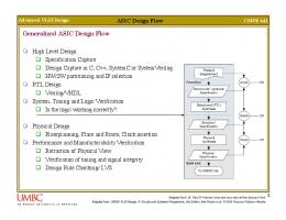
Abstract This paper discusses the Kohonen highly parallel, to match the inherent parallelism neural network (KNN) processor and its KNN of the KNN. It sub-contracts the processing of computation engine microchip. The ASIC each individual neuron of the KNN map to design of the KNN processor adopts a novel individual Processing Elements (PE). Due to the implementation approach whereby the representation of each neuron of the computation of the KNN algorithm is implemented KNN map by individual PEs, the performed on the custom ASIC microchip and area requirement for realization of the its operations are governed by a FPGA based architecture on a single ASIC chip proved to be controller. Thus, the ASIC implementation of impractical and rather expensive. In addition to the KNN processor is derived through that, different pattern recognition tasks and may integration between a custom ASIC and command differing neuron-map sizes and hence FPGA. The 3.3V AMI 0.5um CO5M-D process the computation engine of the KARN processor technology was used to achieve the VLSI cannot be implemented to an inflexible fixed design of the computation engine microchip map dimension. Thus, it was concluded that the and the entire design adopted the BBX cell matter was best resolved by detaching the based methodology, which is a viable controller and computation engine on separate ASIC ASICs. conventional to alternative The Neuron-Array Computation Engine (ACE) methodology. of the KARN processor is made up of scalable arrays of Processing Elements (PE) that emulate I. INTRODUCTION the Neuron-Map layer of the KNN. The PEs Neural Networks are models of the human brain execute in a parallel manner to permit that have shown to possess the ability to learn. accelerated simulation of the KNN algorithm. This has made it very suitable for problems that Initial efforts targeting for FPGA device conventional computers are unable to solve, such implementation revealed that even large devices as pattern recognition. With its increasing such as the Altera APEX_20K200 were merely popularity, there is now a demand for dedicated able to implement modest ACE designs of 4x4 neurohardware that offers low -cost high-speed PE arrays. Thus, VLSI implementation was performance with a compact implementation. employed to assure higher compaction and better Neurohardware have specialized architectures execution speed. Also, the cost of a single VLSI optimized for the implementation of neural chip was lower than an off-the-shelf FPGA networks. Thus, to cater to this need, a device. The ACE was also designed to feature neuroprocessor core (KARN) targeting pattern PE-level scalability and Chip- level cascadability. recognition applications was designed to PE-level scalability promotes a simplified implement the Kohonen Neural Network (KNN) process for designing ACE chips with differing algorithm, one of the more popular neural neuron-map dimensions. On the other hand, paradigms. The KNN has been successfully cascadability at chip level would avoid the implemented in various pattem recognition impracticality of realizing large neuron-map applications. In line with designing a high speed dimensions of up to 50x5O neurons on a single neuroprocessor implementing the KNN for real ACE chip. Instead, construction of large maps of time applications, the KARN processor adopted such sizes could be achieved merely through the neuron-array based architecture, which is cascadation of a few ACE chips.
0-7803-8658-2/04/$20.00(c)2004 IEEE
148
ICSE2004 Proc. 2004, Kuala Lumpur, Malaysia
I I KARN CONTROLLER -
ACE MICROCHIP , CUSTOM ASIC -
FPGA ASIC-
Fig. 1 Block Diagram Of KARN Neuroprocessor Core II. THE KOHONEN ANN ALGORITHM
III.
As with most Neural Networks, KNN consists of a learning phase and a recall phase. Algortihm 1 presents the learning phase algorithm while Algorithm 2 presents the recall phase algorithm.
Algorithm 1: The KNN Leamning Algorithm StepO:Initialize weights wi, Set topological neighborhood parameter. Set learning rate parameter. Stepi: While stop is false do steps 2 to 8 Step2:For each input vector x do steps 3 to 5 Step3: For each j, compute:
D(j)= X.(w.-x,).
HARDWARE STRUCTURE OFTHE PROCESSING ELEMENT (PE)
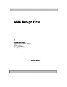
The PE was designed to implement the Euclidean Distance (1) and Weight Update (2) computation of the KNN algorithm. In order to simplify the PE's circuitiy, the Euclidean distance was substituted with the Manhattan distance and the adaptation factor, a, was restricted to the negative orders of two, i.e. 1, 1/2, 1/4, 1/8, 1/16. Although these alterations introduce some error into the measure, it is acceptable as a compromise between accuracy and speed of calculation [6]. The PE was designed to execute 7 different instructions, entirely relevant to the implementation of the Recall & Learn phase computations.
Step4:Find indexj such that D&) is a minimum StepS:For all unitsj within a specified neighborhood ofj andfor all i: w,j (new) = w,,(old) + a(x, - wj (old)) ..(2) Step6:Update learning rate Step7:Reduce radius of topological
neighborhood at specified times Step8: Test stopping condition
Algorithm 2: The KNN Recall Algorithm Stepl:For eachj, compute:
(W inxi) D(j) = Step2:Find indexj such that DO) is a minimum Fig. 2 PE Functional Block Diagram
0-7803-8658-2/04/$20.00(c)2004 IEEE
149
ICSE2004 Proc. 2004, Kuala Lumpur, Malaysia amto
ocw 1
Dab out
Poaw9
dcwO
1 iv
1Fw
COLO
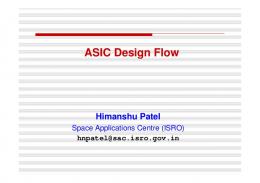
Fig. 3 The Scalable ACE Design Consisting Arrays Of PEs
0
J1
Oatb
Fig. 4 The ACE_2x2 Functional Block Diagram
IV. ThE STRUCTURE OF THE NEURON-ARRAY COMPUTATION ENGINE (ACE)
The scalable structure of the ACE design is illustrated in Figure 2. The scalable ACE design consists of only 2 submodules, being the previously described PE module and the Transmission Module (TL). All PEs and TL modules of the ACE are clocked with the same signal. Thus, its operation is thoroughly synchronized. The TL module is responsible in transmitting out all read PE weight vectors in a row-by-row fashion and aso plays an important role in supporting the cascadability feature of the ACE. When an ACE is cascaded with other ACE chips and is not actively processing, the TL module transmits data from lower to upper ACE chips through it. As illustrated by Figure 2, the ACE design can be scaled to any array dimension, simply by placing an equal number of rows and columns of PEs to form a symmetrical array dimension. A single column of TL modules is then placed next to row_n to form the transmission bus. The intended ACE design is finally concluded by making appropriate signal connections between the used modules. A 17bit instruction bus from the KARN
LOAD and READ functions. The row-column signals are particularly important in synchronizing the countdown operation of all PE Transfer Registers in the BMN search function. Output row and column signals are used also in the BMN search operation to denote the winning PE's coordinate within the array. V. VLSI DESIGN OF THE ACE_2X2 CHIP
For prototyping and proof-of-concept purposes, a neuror-map ACE chip, dubbed the ACE_2x2 was designed using the AMI 0.5um C05M-D process technology. The entire design, from design entry till tape-out adopted a new and unconventional BBX cell-based design methodology, developed in-house at UTM. The hardware modeling of the ACE_2x2 was done using VHDL and the in-house developed design entry tool, VHDLmg. Upon functional verification, the VHDL design of the ACE_2x2
2x2
ratified for ASIC back-end design. The Tanner LrEdit Layout tool was employed to produce the physical design of the ACE_2x2 through means of P&R and full-custom layout. The layouts of the ACE_2x2 sub-modules; the PE and TL modules were produced through P&R based on timing verified logic netlists produced processor controller is connected to the ACE to by Synopsys DC. The P&R stage utilized cells transmit instruction streams for PE operations. from the AMI MTC35000 Standard Core Cell The instruction stream is received by the f row library. The IO ring design on the other hand was of PEs and subsequently wansmitted to the achieved through the full-custom manner and following rows in a systolic manner. Individual used pad- limited I/O cells from the AMI row and column control signals, also originating MTC35 1000 Standard V/O Cell library. The final from the KARN controller, is used to address full-chip design was then derived and found to be specific PEs or rows and column groups of PEs 16.9 sq.mm in area of 4.l lum x 4.1 l um and to and activates the appropriate rows and columns contain 41,028 transistors. Upon functional, in an orderly manner for the RECALL, LEARN, timing and physical verification for process
0-7803-8658-2/04/$20.00(c)2004 IEEE
150
was
ICSE2004 Proc. 2004, Kuala Lumpur, Malaysia
design & electrical rule compliance, the ACE 2x2 was taped out in GDSII format for submission to the IC foundry, Europractice IMEC, Belgium. Aif 84-pin PGA package was chosen to house the 49-I/O-signal ACE_2x2 design. The design is currently being fabricated at Europractice and expected back by late September 2004, given a tur-around period of 3 months.
(ACE) design and the VLSI design of a prototype ACE_2x2 chip. The ACE_2x2 chip is a composition of 4 PEs and 2 TL modules. The VLSI design was achieved using the AMI 0.5um C05M-D process and is able to execute at a minimum operating frequency of 86.66 MHz. The chip is currently being fabricated in Europractice IMEC, Belgium and is expected to be retrieved by late September, 2004. Upon retrieval, the chip will be integrated with the FPGA based controller of the KARN processor to implement the KNN algorithm for real time pattern recognition applications. VII. REFERENCES
[1]
C. Lindsey. "Neural Networks in Hardware: Architectures, Products and Applications", http.//www.particle.kth.selklindsey), 1998. [2] T. Schoenauer, A. Jahnke, U. Roth, H. Klar, "Digital Neurohardware: Principles and perspectives", Neural Networks in Applications, Magdeburg, 1998. [3] R. Togneri, Y. Attikiouzel, "Parallel implementation of the Kohonen algorithm on Transputer", lnt. Joint Conf. on Neural Networks(IJCNN91) Vol.2 Singapore, 1991. Fig. 5 ACE_2x2 Bonding Diagram [4] M. Melton, Tan Phan, D. Reeves, D. Van den Bout, "The TlnMANN VLSI Chip", VI. PERFORMANCE EVALUATION IEEE Trans. on Neural Networks, Vol.3, No. 3, 1992. Post-layout timing analysis for worst-case conditions of 2.7V supply voltage and 80 [5] T.Kohonen, "The 'neural' phonetic typewriter", Computer, 1988. environmental Centigrade temperature R Beale, T Jackson. "Neural Computing: [6] ascertained the design to have a critical path of An Introduction." Adam Hilger, IOP lesser than 12ns. Subsequently, final round of Publishing Ltd,, p.25 1990. simulations functional operations of the K. Goser, U. Rueckert. "A S. [7] Rueping, ACE_2x2 at 86.66 MHz with the supply voltage for Feature Maps", Chip Selforganizing being set at 3.3V and simulation temperature set Fourth International on Conference at 27 Centigrade. For evaluation in terms of Networks and Microelectronics Neural for neurohardware performance metrics, the ACE Fuzzy Systems, Italy, 1994. design for a 50x50 chip is used instead of the ACE_2x2 and is able to deliver up to 37500 Million Connections Per Second (MCPS) and 27667 Million Connections Update Per Second (MCUPS). The delivered MCPS and MCUPS performances were significantly better than existing documented efforts. VI. CONCLUSION The paper presents the hardware structure of the scalable Neuron-Array Computation Engine
0-7803-8658-2/04/$20.00(c)2004 IEEE
151


![[Full] Physical Design Essentials: An ASIC Design ... - Google Sites](https://m.moam.info/img/260x300/full-physical-design-essentials-an-asic-design-goo_64783b01097c4744708c98f4.jpg)