Available online at www.sciencedirect.com
ScienceDirect Procedia Computer Science 46 (2015) 507 – 516
International Conference on Information and Communication Technologies (ICICT 2014)
Biometric based Unique ID Generation and One to One Verification for Security Documents Sajan Ambadiyila , K S Soorejb, V P Mahadevan Pillaic,* a
Center for Development of Imaging Technology, Thiruvanthapuram-695027, Kerala, India b Jawaharlal college of Engg. And technology, Lakkidi, Palakkad- 67930, India Department of Optoelectronics, University of Kerala, Kariavattom, Thiruvanthapuram-69558, India
c
Abstract Security documents like certificates, land revenue documents, etc., have only the individual’s name, address, and in some cases a photo as means of personal identification. This makes criminal impersonation an easy task. This paper proposes a method for creating a unique ID based on the core point of the fingerprint of an individual. The minutia features of the fingerprint are extracted with the core point as the reference. The numerical value thus generated is used to create the unique ID in the form of a QR code and this is printed in the security documents. There are current technologies to convert a fingerprint to barcode but the method proposed in this paper is more suitable for use in security documents. © 2015 2014 The The Authors. Authors.Published Publishedby byElsevier ElsevierB.V. B.V.This is an open access article under the CC BY-NC-ND license © Peer-review under responsibility of organizing committee of the International Conference on Information and Communication (http://creativecommons.org/licenses/by-nc-nd/4.0/). Technologiesunder (ICICT 2014). of organizing committee of the International Conference on Information and Communication Peer-review responsibility Technologies (ICICT 2014) Keywords: Anti- Counterfeiting; Fingerprints; Minutia extraction; Impersonation
1. Introduction Valuable documents like certificates, passports, driver's licenses, and land revenue documents contain some security features, which make counterfeiting difficult. But once a fraudulent individual with technical knowledge gets hold of such a document, he/she can easily indulge in criminal impersonation. This is easy because such
* Corresponding author. Tel.: +91-9447827852; fax: +91-471-2381646. E-mail address: *
[email protected]
1877-0509 © 2015 The Authors. Published by Elsevier B.V. This is an open access article under the CC BY-NC-ND license (http://creativecommons.org/licenses/by-nc-nd/4.0/). Peer-review under responsibility of organizing committee of the International Conference on Information and Communication Technologies (ICICT 2014) doi:10.1016/j.procs.2015.02.075
508
Sajan Ambadiyil et al. / Procedia Computer Science 46 (2015) 507 – 516
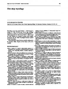
documents only have name, address, and a photo of the owner for personal identification. All these features could be easily duplicated. Use of biometric features will help to reduce the risk of forgery1. Currently the use of biometric feature in such documents is very rare. But to prevent impersonation and avoid counterfeiting of such documents, the right answer is the use of biometric methods. The use of intrinsic physical and behavioural traits of a human being to uniquely recognize an individual is called as biometrics. Biometric methods generally use a part of human body to identify a person and they are highly accurate. The biometric traits of an individual obtained must be transferred to the documents in some way. Computer chips and RFID tags have been used for storing biometric information2. For example, electronic passport issued by Republic of Germany contains an electronic chip with biometric information of the individual. Developing such a document with an RFID tag will be a very complex and costly process. Also the lifetimes of such devices are very limited. Hence development of new cost effective methods having long lifetime for transferring the biometric information to documents is of prime importance in the technological point of view. Compared to computer chips and RFID tags, data hiding technologies like Quick Response (QR) code are much cheaper and do not require specialized hardware for retrieving data. QR codes are inexpensive, and they are passive read-only elements whose content cannot be altered. Decoding of the QR code can be done by many low-cost devices, including smart phones3. As QR Code has high capacity, all the standardized features extracted from the fingerprints could be encoded in it. It can be read from any direction and standard encryption techniques can be applied to the QR code to make it even more secure. Currently there are technologies that convert fingerprint to data hiding technologies like barcode4, which uses Vucetich method to classify the prints. Then the prints are sub-classified according to the previous classification, and are converted into alphanumeric codes and then to corresponding barcodes. But this method is too complex and costly for our application, that is, to use in security documents like certificates and land revenue documents. This paper reports an easier technique for the development of a unique ID in the form of a QR (Quick Response) code by extracting the standardized feature based on the core point of the fingerprint of an individual for printing in the documents for the personal identification. 2. Proposed method 2. 1 Fingerprints-an overview Fingerprint, one of the most dominant biometric traits, is the impression of the friction ridges on finger. A friction ridge is a raised portion of the epidermis on the fingers and they are persistent throughout life. Two fingerprints, even if they are from identical twins, are never exactly alike. Among the most popular biometric features like Fingerprint, Iris and face recognition, fingerprint is the most dominant trait. It is used for personal recognition in several personal and civilian applications because of its properties like uniqueness and unchangeability. Fingerprints can be classified into different types based on the general ridge formation such as arch, loop, whorl, and composite as shown in Fig. 1.
Fig. 1 Basic fingerprint ridge patterns
In Arch pattern ridges run from one side to another continuously. The ridges in arch pattern run without any backward turn or recurve. Loop patterns are those in which the ridges make a backward turn without twisting, and hence centre of the print appears to form a hairpin. The ridges in Whorl pattern forms a very complex pattern with
Sajan Ambadiyil et al. / Procedia Computer Science 46 (2015) 507 – 516
509
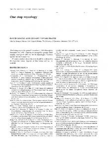
two or more deltas. The composite pattern as the name suggests comprises a combination of two or more of arch, whorl and loop patterns5. In a fingerprint pattern there are certain unique points, like core and delta, which are generally termed as the singular points. Fig. 1 shows core and delta in a fingerprint. Singular points are those points in which there is an abrupt change in the ridge patterns. Here the curvature of ridges is higher than normal. Among the singular points core points are the most reliable as they can be seen in most fingerprints. Core points can be defined as the topmost point of the innermost ridge lines. It may also be defined as the point with highest curvature in fingerprint ridges6. In fingerprints, Minutiae, the discontinuities in the ridge pattern that interrupt the otherwise smooth flow of ridges, are major features which are used to compare one print with another. There are several types of Minutiae like ridge ending, ridge bifurcation, short ridge, island, spur, bridge etc.
Fig. 2 Fingerprint ridge patterns and Minutiae
Out of these, two major types of minutia, the ridge ending/termination and the ridge bifurcation are selected for the development of the proposed system 7. Only these two are selected because the aim of this study is to create a unique ID for security documents such as university certificates and other valuable documents. In that case, the verification procedure that is employed is one to one cross verification. So there is no need to extract the details of all type of minutia. Fig. 2 shows the ridge pattern along with the major minutia forms. It can be inferred from the figure that a ridge ending means the abrupt ending of a ridge and ridge bifurcation means a single ridge that divides into two ridges.
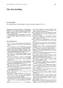
Fig. 3 Flowchart of the barcode generation process
510
Sajan Ambadiyil et al. / Procedia Computer Science 46 (2015) 507 – 516
After identifying the features that make the fingerprint unique, they are extracted in a standardized manner. Then these extracted features are converted to numerical values. These numerical values are used to generate a unique ID in the QR code format using any QR code generating software. Flowchart of this whole process is given in Fig. 3. 2.2 Unique ID Generation An image processing tool like MATLAB is used for the conversion of fingerprint to unique ID in the form of a QR code. The most important step is to identify a unique point in the fingerprint which will serve as a reference point. All the other minutia features will be calculated with this point as the origin. And hence the fingerprint of the same individual taken in different orientations will all produce the same ID. Core point of the fingerprint is one such unique point. There are several methods proposed to find the core point of a fingerprint. One such method is based on orientation field of the fingerprint. In this method a gradient based technique is used to obtain the orientation field. Then the orientation field thus obtained is smoothened. A mask is then operated on the field for detecting core point8. Another approach proposes coarse core point detection by using a method called as the Direction of curvature technique. Then the fine finding of the core point is done by another technique called as the geometry of region technique 9. But the most common method used to find the core point is the Poincaré Index Method. The first step before applying the Poincaré index method is to transform the input fingerprint image into an orientation field image. The orientation field image of a fingerprint is as shown in Fig. 4.
Fig. 4 Orientation field image of fingerprint
The Poincaré index is defined for each position in the orientation field and it is generally computed by considering some elements around that position10. Consider a case in which 8 positions are taken around the target position. Let θ (i, j ) be the (i, j )-element of an orientation field image and 0 ≤ θ (i, j ) < 2π for any (i,j ). Let δk(i, j ) = θ (ik+1, jk+1) - θ (ik, jk),
(1)
for 0 ≤ k ≤6 and δ7 = θ (i0, j0) - θ (i7, j7). Then, the Poincaré index of an element (i,j ) is defined to be P (i, j ) =(1/2 π).∑
∆ (, )
(2)
511
Sajan Ambadiyil et al. / Procedia Computer Science 46 (2015) 507 – 516
( , ), if | ( , )| < Where
Δk(i,j)=
+
( , ), if | ( , )| ≤ − − ( , ), otherwise
(3)
The Poincaré index has the value 1/2, 0, -1/2, or 1. A core point is expected to occur at the position of which Poincaré index is 1/2. In this paper an existing MATLAB Demo code is used to find the core point11. The output image after marking the core point using this Demo code is as shown in Fig. 5.
Fig. 5 Fingerprint with core point marked
After finding the core point, the minutia points are extracted by taking the core point as reference. The steps to extract the minutia point are as follows. The fingerprint image to be converted to the unique code is taken as the input as shown in Fig. 6a. This fingerprint image is enhanced so that it will have the required quality. It is very critical to reliably extract minutiae from the input fingerprint images. Reliable extraction of minutiae features is heavily dependent on the quality of the input fingerprint image12. Hence image enhancement is very important because it makes identification of the minutia features easier. After enhancement the image is binarized. In a binary image each pixel is stored as a single bit—i.e., 0 or 1. The Fig. 6b below shows a binarized fingerprint image. Ridge thinning is then done to eliminate the redundant pixels of ridges. Ridge thinning makes the entire ridges just one pixel wide. The thinning function used in MATLAB is ‘bwmorph’. Thinning is done so that the image processing steps which come after it are easier to perform. Fig. 6c shows the fingerprint image after thinning.
Fig.6. (a) Input image (b) Image after enhancement and binarization (c) Image after thinning
The next step is called as minutia marking. Minutia marking is a very important step and it employs the concept of crossing number. The differences between intensity values of all the adjacent pixels are found out and these results are added together. Dividing the sum by two gives the Crossing number13. If crossing Number is 1 then minutiae
512
Sajan Ambadiyil et al. / Procedia Computer Science 46 (2015) 507 – 516
point is a termination. If crossing Number is 2 then minutiae point is a normal point. If crossing Number is 3 or more than 3 then minutiae point is a bifurcation. Marking is done by selecting a suitable window size. In this study a 3X3 window is considered and the number of one valued neighbouring pixels of the center pixel is calculated. If the central pixel is 1 and it has only one neighbouring pixel with the value 1, then the central pixel is a termination. If the central is 1 and it has 3 neighbouring pixels with pixel value 1, then the central pixel is a bifurcation. If the central is 1 and has 2 neighbouring pixels with value 1, then the central pixel is a usual pixel. Fig. 7 shows the 3X3 window for each case.
Fig.7. 3X3 window for (a) Ridge Ending (b) Normal ridge (c) Ridge bifurcation
After minutia marking, the image will be as shown in Fig. 8a. There will be a lot of spurious minutiae. It should be processed. The different process applied to the image for eliminating spurious minutia is as follows: Process 1 - if the distance between a termination and a bifurcation is smaller than a particular distance D, these minutiae are removed. Process 2- if the distance between two bifurcations is smaller than D, these minutiae are removed. Process 3- if the distance between two terminations is smaller than D, these minutiae are removed. Where, D is the Euclidean distance. In this study D is taken as 6 pixels. So after applying all these processes and removing all the spurious minutiae the image will have only unique minutiae. Such unique minutiae are needed for making each fingerprint a distinct one. After the removal of the spurious minutia the image will be as shown in Fig. 8b.
Fig. 8. (a) Image after marking all minutia (b) Image after removing spurious minutia (c) Image after applying ROI
Even after this step there will be a large number of minutiae. But only a few minutiae which are absolutely unique for that particular fingerprint is needed to generate the unique ID. For this only the minutiae which are inside a Region Of Interest (ROI) centered around the core point are taken. Here, the Region of interest is a square with suitable pixel area centered around the core point. After application of the Region Of Interest the image will be as shown in Fig. 8c. Now the image only has a minimum required number of minutiae points. All the terminations and
Sajan Ambadiyil et al. / Procedia Computer Science 46 (2015) 507 – 516
513
bifurcations are marked in the image. Each of this termination and bifurcation is now represented by a coordinate of its position and orientation angle. The coordinates of the position can be found out by ‘regionprops’ function in Matlab. Eg: regionprops(‘X’, centroid), where X is the image. ‘regionprops’ measure properties of image regions14. Centroid is the function that gives the coordinates of the minutiae. The first two elements of Centroid will give the x-coordinate and the y-coordinate of the center of mass. While finding the coordinates of the minutia, the origin should be shifted from the default position to the location of the core point as shown in Fig. 9.
Fig. 9 Fingerprint image with core point as the origin
After this the orientation angle of the terminations and bifurcations are found out. Minutiae have its orientation measured between the horizontal axis and the line formed by a minutia ridge, proceeding counter-clockwise. It goes from 0° to 359°. So the minutia is represented by an x coordinate, y coordinate and angle of orientation. Using this a N X 3 matrix is created. This matrix is given to a QR code generating software to generate the barcode. Here the software used is QR Code studio 1.0 by TEC-IT15. This QR code serves as the unique ID that can be printed on security documents to prevent impersonation. Fig. 10 shows the conversion of the matrix representing the numerical values of minutia to QR code.
Fig.10 Matrix to QR code
Where (BX1, BY1), (BX2, BY2),…….,(BXk, BYk) represent the coordinates of bifurcations and BO1, BO2………. BOk represents the orientation of bifurcations, with k being the total number of bifurcations and (TX1, TY1), (TX2, TY2),…….,(TXk, TYk) represent the coordinates terminations and TO1, TO2………. TOk represents the orientation of terminations, with k being the total number of terminations. This entire process is explained in the block diagram given in Fig. 11.
514
Sajan Ambadiyil et al. / Procedia Computer Science 46 (2015) 507 – 516
Fig.11. Block diagram of the entire process
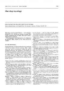
3. Analysis and Discussion To analyze the proposed system, fingerprints of more than hundred individuals were collected and their corresponding minutia parameters were extracted. In order to check the authenticity of the method ten fingerprint samples each, from ten individuals were also collected. To evaluate the performance of the proposed system the following parameters have to found out: a. False Acceptance Rate(FAR) – It is the ratio of, the number of times the system incorrectly declares a successful match between two non-matching fingerprints, to the total number of fingerprints. b. True Acceptance Rate(TAR)- It is the ratio of, the number of times the system correctly declares a successful match between two matching fingerprints, to the total number of fingerprints. c. False Rejection Rate(FRR) - It is the ratio of, the number of times the system incorrectly declares a non-match between two matching fingerprints, to the total number of fingerprints. d. True Rejection(TR) – It is the ratio of, the number of times the system correctly declares a nonmatch between two non-matching fingerprints, to the total number of fingerprints. For calculating these parameters a term called Score must be calculated at first. Score is calculated in order to verify whether the two fingerprints are matching16. Score is defined as the ratio of Number of matched minutia pair to the total number of minutia of the fingerprint. Two fingerprints are said to be matched fingerprints if score is greater than a set threshold value. In this study we have set the threshold value as 75%. Using the collected fingerprints all the parameters mentioned above were calculated and the corresponding graphs were plotted. Fig. 12(a) shows the graph for False Acceptance Rate. In this study fingerprints of 25 individuals were used to calculate
515
Sajan Ambadiyil et al. / Procedia Computer Science 46 (2015) 507 – 516
FAR. It can be seen from the graph that the value of FAR are low. Fig. 12(b) shows the graph for True acceptance rate. In this study 10 fingerprints of 10 individuals were used to calculate the TAR. It can be seen from the graph that the value of TAR is very high. Fig. 12(c) shows the graph for False rejection rate. In this study 10 fingerprints of 10 individuals were used to calculate the FRR. It can be seen from the graph that the value of FRR is low. Fig. 12(d) shows the graph for True Rejection. In this study fingerprints of 25 individuals were used to calculate the TR. It can be seen from the graph that the value of TR is high.
False Acceptance Rate
True Acceptance Rate
3.5 3 2.5 2 1.5 1 0.5 0
FAR(in %)
TAR (in %)
120 100 80 60 40 20 0 0
10
20
30
0
5
Person
Person
(a)
(b)
True Rejection
35 30 25 20 15 10 5 0
TR (in %)
FRR (in %)
False Rejection Rate
0
2
4
6
8
10
100.5 100 99.5 99 98.5 98 97.5 97 96.5 0
10
Person
(c)
10
20
30
Person
(d)
Fig. 12 (a) False Acceptance Rate (b) True Acceptance Rate (c) False Rejection Rate (d) True Rejection
Ideally the values of True acceptance rate and true rejection must be very high and the values of False acceptance and false rejection must be low. From the above graphs it can be inferred that the proposed system gives such results. So using this method we can generate a unique QR code and hence it can be used in security documents to prevent impersonation. Though the analysis produced favourable results the proposed system has certain limitations. Based on the way in which the individual places his/her finger in the fingerprint sensor, the fingerprint image that is obtained may not have certain portions when compared to the image stored in the database. Hence some of the minutia points may be missing and the ID generated will not be unique. A possible solution is to collect 5 fingerprint samples from the same individual and extract the minutia from each of them. Then select the minutia that are common to all 5
516
Sajan Ambadiyil et al. / Procedia Computer Science 46 (2015) 507 – 516
fingerprints and use it to generate the unique ID. Another problem associated with fingerprints that affects every fingerprint based system is that certain people’s fingerprints are worn away with time as shown Fig. 13.
(a)
(b)
(c)
Fig.13. A worn out fingerprint of an individual (a) Middle finger (b) Little finger (c) Ring finger
A possible solution to this problem is to develop a multimodal biometric system by embedding other biometric traits like Iris, vein pattern and face along with the fingerprint to the QR code. 4. Conclusion This paper proposes a simple and cost effective anti-counterfeit system to generate a unique ID for security documents based on the core point of the fingerprint. The proposed method is more effective than the earlier methods since we are identifying the person using the fingerprint. Real-time acquisition, recognition and verification is possible with this system. Here minutia features of the fingerprint are extracted with the core point as reference point and this is used to generate a QR code. The unique ID thus formed can be printed on security documents to prevent criminal impersonation. Analysis of the proposed system shows that the system has satisfactory performance parameters. Our future work will focus on developing a multimodal biometric unique ID generation system to eliminate the limitations of the proposed system. References 1. 2. 3. 4. 5. 6. 7. 8. 9. 10. 11. 12. 13. 14. 15. 16.
Justin Picarda, Claus Vielhauerb and Niels Thorwirth. Towards Fraud-Proof ID documents using multiple data hiding technologies and biometrics. SPIE 2004 ;5306 http://www.epass.de Marco Querini and Giuseppe F. Italiano. Facial Biometrics for 2D Barcodes. IEEE Federated Conference on Computer Science and Information Systems 2012; p. 755–762 Eduardo Salva Calcagno. Person identification procedure by converting fingerprints and genetic codes into barcodes, and the device used in this procedure. US patent 2007; US 20070041622 A1 Tim Thompson and Sue Black. Fingerprints. In: Vivianne Galloway, Dave Charlton. Forensic Human Identification - An Introduction. London: CRC Press; 2007. p. 57-72 G.A. Bahgat, A.H. Khalil, N.S. Abdel Kader, S. Mashali. Fast and accurate algorithm for core point detection in fingerprint images. Egyptian Informatics Journal 2013; 14:15–25 Lin Hong, Anil Jain, Sharath Pankanti and Ruud Bolle. Identity authentication using fingerprints. IEEE 1997; 85:1365-1204 Ashish Mishra, Dr.Madhu Shandilya. Fingerprint’s Core Point Detection using Gradient Field Mask. International Journal of Computer Applications 2010 ;8 Atipat Julasayvake and Somsak Choomchuay. An Algorithm For Fingerprint Core Point Detection. IEEE 9th International Symposium on Signal Processing and Its Applications 2007; p. 1-4 Ali Ismail Awady and Kensuke Baba. Singular Point Detection for Efficient Fingerprint Classification. International Journal on New Computer Architectures and Their Applications (IJNCAA) 2012; 45:p. 1-7 http://www.advancedsourcecode.com/fingerprint.asp Lin Hong, Anil Jain and Yifei Wan. Fingerprint image enhancement: Algorithm and performance evaluation. IEEE Transaction on pattern analysis and machine intelligence 1998; 20:p.777-789 Ravi. J, K. B. Raja, Venugopal. K. R. Fingerprint Recognition Using Minutia Score Matching. International Journal of Engineering Science and Technology 2009;1 http://www.mathworks.in/help/images/ref/regionprops.html#bqkf8ln http://www.tec-it.com/en/start/Default.aspx G.R. Sinha, Sandeep B. Patil. In: Biometrics: Concepts and Applications. India: Wiley India publications; 2013.