American Journal of Electrical Power and Energy Systems 2013; 2(3): 94-97 Published online June 30, 2013 (http://www.sciencepublishinggroup.com/j/epes) doi: 10.11648/j.epes.20130203.15
Designing of dynamic voltage restorer (DVR) to improve the power quality for restructured power systems M. Kavitha1, T. Chandrasekhar2, D. Mohan Reddy3 1
Dept of Computational Engineering, APIIIT, RGUKT, Nuzvid, A.P,India Dept of CSE, APIIIT, RGUKT, Nuzvid, A.P,India 3 Dept of EEE, SVIET,Pedana (M), Krishna (Dt),A.P,India 2
Email address:
[email protected](M. Kavitha),
[email protected](T. Chandrasekhar),
[email protected](D. M. Reddy)
To cite this article: M. Kavitha, T. Chandrasekhar, D. Mohan Reddy. Designing of Dynamic Voltage Restorer (DVR) to Improve the Power Quality for Restructured Power Systems. American Journal of Electrical Power and Energy Systems. Vol. 2, No. 3, 2013, pp. 94-97. doi: 10.11648/j.epes.20130203.15
Abstract: In Restructured power systems, Power quality is one of the major concerns in the present era. The problem of harmonics, voltage sags and swells and its major impact on sensitive loads are well known. To solve this problem, custom power devices are used. One of those devices is the Dynamic Voltage Restorer (DVR), which is one of the most efficient and effective modern custom power devices used in power distribution networks for the power quality improvement. Control of power quality problems involves cooperation between network operator (utility), customer and equipment manufacturer. A Dynamic Voltage Restorer (DVR) is a distribution voltage DC-to-AC solid-state switching converter that injects three single phase AC output voltages in series with the distribution feeder and in synchronism with the voltages of the distribution system. A DVR is interface equipment between utility and customer connected in series between the supply and load to mitigate the three major power quality problems, namely the harmonics, voltage sags, and swells etc. This paper concentrates on the designing of Dynamic Voltage Restorer (DVR) for the harmonics compensation so that it can improve the Power Quality (PQ).
Keywords: Dynamic Voltage Restorer (DVR), Harmonics,Voltage Swell And Power Quality
1. Introdution Power quality may be defined as any power problems manifested in voltage, current or frequency deviations that result in failure or mis -operation of customers equipment.Power Quality (PQ) is an important measure of an electrical power system. The term PQ means to maintain purely sinusoidal current wave form in phase with a purely sinusoidal voltage wave form. The power generated at the generating station is purely sinusoidal in nature. The deteriorating quality of electric power is mainly because of current and voltage harmonics due to wide spread application of static power electronics converters, zero and negative sequence components originated by the use of single phase and unbalanced loads, reactive power, voltage sag, voltage swell, flicker, voltage interruption etc. To improve the power quality traditional compensation methods such as passive filters, synchronous capacitors, phase advancers, etc. were employed. However traditional controllers include many disadvantages such as fixed
compensation, bulkiness, electromagnetic interference, possible resonance etc.. These disadvantages urged power system and power electronic engineers to develop adjustable and dynamic solutions using custom power devices. Custom power devices are power conditioning equipments using static power electronic converts to improve the Power Quality (PQ) of distribution system customers.
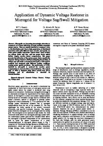
2. Dynamic Voltage Restorer (DVR) The schematic diagram of Dynamic Voltage Restorer (DVR) is shown below. DVR (Dynamic Voltage Restorer) is a static var device that has seen applications in a variety of transmission and distribution systems. It is a series compensation device, which protects sensitive electric load from power quality problems such as voltage sags, swells, unbalance and distortion through power electronic controllers that use voltage source converters (VSC).
American Journal of Electrical Power and Energy Systems 2013; 2(3): 94-97
95
(DVR), a sag on one phase may result in a swell on another phase, so the VSC must be capable of handling both sags and swells simultaneously. The variable output voltage of the inverter is achieved using PWM scheme. 3.3. Filter Unit
Figure 1. Schematic diagram of a Dynamic Voltage Restorer
A DVR, Dynamic Voltage Restorer is a distribution voltage DC-to-AC solid-state switching converter that injects three single phase AC output voltages in series with the distribution feeder and in synchronism with the voltages of the distribution system. The series voltage controller is connected in series with the protected load. Usually the connection is made via a transformer, but configurations with direct connection via power electronics also exist. The resulting voltage at the load bus bar equals the sum of the grid voltage and the injected voltage from the DVR. The converter generates the reactive power needed while the active power is taken from the energy storage. The energy storage can be different depending on the needs of compensation. DVR can compensate voltage at both transmission and distribution sides. Usually a DVR is installed on a critical load feeder. During the normal operating condition (without sag condition) DVR operates in a low loss standby mode during this condition the DVR is said to be in steady state. When a disturbance occurs (abnormal condition) and supply voltage deviates from nominal value, DVR supplies voltage for compensation of sag and is said to be in transient state.
3. DVR Components The major components that are used in Dynamic Voltage Restorer (DVR) are explained below. 3.1. Energy Storage Unit The required energy for compensation of harmonics, load voltage during sag can be taken either from an external energy storage unit (batteries) or from the supply line feeder.
The nonlinear characteristics of semiconductor devices cause distorted waveforms associated with high frequency harmonics at the inverter output. To overcome this problem and provide high quality energy supply, a harmonic filtering unit is used. This can cause voltage drop and phase shift in the fundamental component of the inverter output, and has to be accounted for in the compensation voltage. 3.4. Series Injection Transformers Three single-phase injection transformers are used to inject the missing voltage to the system at the load bus. To integrate the injection transformer correctly into the DVR, the MVA rating, the primary winding voltage and current ratings, the turn-ratio and the short-circuit impedance values of transformers are required. The existence of the transformers allow for the design of the DVR in a lower voltage level, depending upon the stepping up ratio. In such case, the limiting factor will be the ability of the inverter switches to withstand higher currents. 3.4. Controller and Auxiliary Circuits By-Pass switches, breakers, measuring and protection relays are some auxiliaries to the DVR block, in addition to the controller of the DVR. 3.6. Carrier Phase Shifting Pulse Width Modulation (PWM) Carrier phase-shift sinusoidal pulse width modulation (PS-SPWM) switching scheme is proposed to operate the switches in the system. Optimum harmonic cancellation is achieved by phase shifting each carrier by (k-1) π/n
Where k is the kth inverter, n is the number of seriesconnected single phase inverters. n= (L-1)/2
3.2. Inverter Circuit Since the vast majority of harmonic disturbances and voltage sags seen on utility systems are unbalanced, mostly due to single-phase events, the VSC will often be required to operate with unbalanced switching functions for the three phases, and must therefore treat each phase independently. Mitigation of harmonics and Voltage Sags in a refinery with Induction Motors Using Dynamic Voltage Restorer
(1)
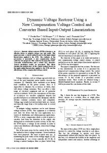
Figure 2. Phase Shifted Carrier PWM
(2)
96 M. Kavitha et al.: Designing of Dynamic Voltage Restorer (DVR) to Improve the Power Quality for Restructured Power Systems
Fig-2 shows the PSCPWM. In general, a multilevel inverter with m voltage levels requires (m–1) triangular carriers. In the PSCPWM, all the triangular carriers have the same frequency and the same peak-to-peak amplitude, but there is a phase shift between any two adjacent carrier waves, given by φcr=3600/ (m–1). The modulating signal is usually a three-phase sinusoidal wave with adjustable amplitude and frequency. The gate signals are generated by comparing the modulating wave with the carrier waves. It means for five-level inverter, four triangular carriers are needed with a 90° phase displacement between any two adjacent carriers. In this case the phase displacement of Vcr1 = 0°, Vcr2 = 90°, Vcr1- = 180° and Vcr2- = 270°.
4. Operation In normal conditions, the dynamic voltage restorer operates in stand-by mode. However, during disturbances, nominal system voltage will be compared to the voltage variation. This is to get the differential voltage that should be injected by the DVR in order to maintain supply voltage to the load within limits. The amplitude and phase angle of the injected voltages are variable, thereby allowing control of the real and reactive power exchange between the dynamic voltage restorer and the distribution system. The DC input terminal of a DVR is connected to an energy storage device of appropriate capacity. As mentioned, the reactive power exchange between the DVR and the distribution system is internally generated by the DVR without AC passive reactive components. The real power exchanged at the DVR output AC terminals is provided by the DVR input DC terminal by an external energy source or energy storage system.
5. Basic Principle The basic idea of a DVR is to inject the missing voltage cycles into the system through series injection transformer whenever voltage sags are present in the system supply voltage. As a consequence, sag is unseen by the loads. During normal operation, the capacitor receives energy from the main supply source. When voltage dip or sags are detected, the capacitor delivers dc supply to the inverter. The inverter ensures that only the missing voltage is injected to the transformer. A relatively small capacitor is present on dc side of the PWM solid state inverter and the voltage over this capacitor is kept constant, by exchanging energy with the energy storage reservoir. The required output voltage is obtained by using pulse-width modulation switching pattern. As the controller will have to supply active as well as reactive power, some kind of energy storage is needed. In the DVRs that are commercially available now large capacitors are used as a source of energy.
6. Caution DVRs may provide good solutions for end-users subject to unwanted power quality disturbances. However, there is a caution regarding their application in systems that are subject to prolonged reactive power deficiencies (resulting in low voltage conditions) and in systems that are vulnerable to voltage collapse. In many cases, the main protection of the power system against voltage collapse is the natural response of load to decrease demand when system voltage drops. The application of DVRs would tend to maintain demand even when incipient voltage conditions are present. As a result, this reduces the innate ability to prevent a collapse and increases the chance of cascading interruptions. In addition, from the transmission viewpoint, the dynamic voltage restorer would extend the voltage range if the load is a constant power type. The combination of direct-connected DVRs, voltage-switched capacitor banks and on-load tap-changing distribution transformers, leads to more current drawn from the transmission system during periods of reactive deficiency and low voltages. Therefore, when applying DVRs, it is vital to consider the nature of the load whose voltage supply is being secured, as well as the transmission system which must tolerate the change in voltage-response of the load. It may be necessary to provide local fast reactive supply sources in order to protect the system, with the DVR added, from voltage collapse and cascading interruptions. A comprehensive simulation study, which includes the transmission system, is highly recommended.
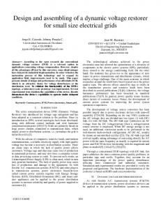
7.Matlab Simulink Circuit The matlab simulink circuit diagram of Dynamic Voltage Restorer (DVR) is shown below. This will give the voltage output waveforms by using with and without DVR.
Figure 3. Matlab simulink circuit diagram of Dynamic Voltage Restorer (DVR)
8. Results The input and outputs of without and with Dynamic Voltage Restorer (DVR) for the above circuit are as shown
American Journal of Electrical Power and Energy Systems 2013; 2(3): 94-97
below. The three phase ac supply as input for the designed circuit in the form of waveform is as shown below.
Figure 4. Input voltage waveform
97
9. Conclusion The Dynamic Voltage Restorer (DVR) is a promising and effective device for power quality enhancement due to its quick response and high reliability. The conclusion is that the DVR is an effective apparatus to protect sensitive loads from short duration harmonics and voltage swells and sags. The DVR can be inserted both at the low voltage level and at medium voltage level. The series connection with the existing supply voltages makes it effective at locations where voltage dips are the primary problem. However, the series connection makes the protection equipment more complex as well as the continuous conduction losses and voltage drop. The role of a DVR in mitigating the power quality problems in terms of harmonics, voltage sag, swell and is explained.
8.1. Without DVR The output waveform of the circuit without using Dynamic Voltage Restorer (DVR) is as shown below. In this waveform we can easily observe the harmonics effect which shows an effect on power quality. This can problem can be solved by using Dynamic Voltage Restorer (DVR).
References [1]
S. Chen, G. Joos, L. Lopes, and W. Guo.” A nonlinear control method of dynamic voltage restorer” , IEEE 33rd Annual Power Electronics Specialists Conference. pp. 8893.Sept2002.
[2]
Ghosh and G. Ledwich. ” Power Quality Enhancement Using Custom Power Devices”, 2002. Kluwer Academic Publishers.
[3]
Math H.J. Bollen, ”Understanding power quality problems: voltage sags and interruptions”, IEEE Press, New York, 2000.
[4]
Sasitharan S., Mahesh K. Mishra, Member, IEEE, B.Kalyan Kumar, and Jayashankar V., member, IEEE, ” Rating and Design Issues of DVR Injection Transformer”, IEEE Press., New York, 2008.
[5]
Madrigal, E.Acha., “Modelling of Custom Power Equipment Using Harmonic Domain Techniques”, IEEE 2000.
8.2. With DVR
[6]
The output waveform of the circuit with Dynamic Voltage Restorer (DVR) is as shown below. In this waveform we can easily observe the elimination of harmonics effect from the above waveform. With this Dynamic Voltage Restorer (DVR) circuit we can maintain the power quality better than without using the DVR.
R.Mienski,R.Pawelek and I.Wasiak., “Shunt Compensation for Power Quality Improvement Using a STATCOM controller Modelling and Simulation”, IEEE Proceedings., Vol.151, No.2. Jan. 2006.
[7]
Bollen, M.H.J.,” Voltage sags in three-phase systems” Power Engineering Review, IEEE, Vol. 21, Issue: 9, pp: 8 11, 15, Sept. 2001.
[8]
Anaya-Lara O, Acha E., “Modeling and analysis of custom power systems by PSCAD/EMTDC”, IEEE Transactions on Power Delivery, Vol.17, Issue: 1, Pages:266 – 272, Jan. 2002.
[9]
G. Yaleinkaya, M.H.J. Bollen, P.A. Crossley, “Characterization of voltage sags in industrial distribution systems”, IEEE transactions on industry applications, vol.34, no. 4, July/August, pp. 682-688, 1999.
Figure 5. Output voltage waveform without DVR
[10] Haque, M.H., “Compensation of distribution system voltage sag by DVR and D-STATCOM”, Power Tech Proceedings, 2001 IEEE Porto, vol.1, pp.10-13, Sept. 2001. Figure 6. Output voltage waveform with DVR