digital image processing applications such as edge detection, ..... Ena(S2),ptr bitl(S3:SS),ptr2 bit(S6),p bit(S7-61),ena out(62) ... Read(63), write(64), clear(6S).
2nd Int'l Conf. on Electrical Engineering and Information & Communication Technology (ICEEICT) 2015 Jahangirnagar University, Dhaka-1342, Bangladesh, 21-23 May 2015
Dynamically Reconfigurable Parallel Architecture Implementation of 2D Convolution for Image Processing over FPGA
Md. Jahiruzzaman, Shumit Saha, Md. Abul Khayum Hawlader
Dept. of Electronics and Communication Engineering l=T
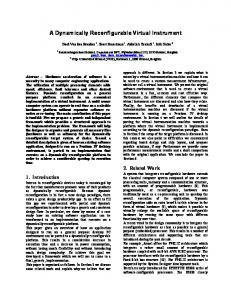
Here, T is a non-negative threshold and R is the output of the mask shown in Fig. 2(a). This mask measures the weighted differences between the center point and its neighbors. The idea is that an isolated point (a point whose gray level is significantly different from its background and which is located in a homogeneous or nearly homogeneous area) will be quite different from its surroundings and thus be easily detectable by this type of mask.
A.B Line Detection The line detected mask given as bellow where the sum of the weights of the mask is zero that indicate the zero response from the mask in the area of constant gray level. The center pixel of the image encountered by the mask is replaced by the output of the mask. The output of the mask is defmed as the sum of the product of neighborhood weighted pixels. The result of the line detected image is shown in Fig. 2(c) with corresponding to the original image Fig. 2(b). [f the mask were
-1 0 1
Image Sharping
Sharpening filters are used to highlight the detail information of an image or to enhance detail that has been blurred. Sharpening filters that are based on first and second derivatives are used for those purposes. The mask used for image sharpening is given as follows where the sum of the weights of the mask is zero. The center pixel of the image encountered by the mask is replaced by the sum of the product of neighborhood weighted pixels. The result of the sharpening image is shown in Fig. 2(e) with corresponding to the original image Fig. 2(a).
C.
Image Smoothing
Smoothing filters are used for blurring and for noise reduction. Blurring is done by removing some small details from an image. Noise reduction can be accomplished by blurring with a linear and non-linear filtering. The output of a smoothing filter is simply the average of the pixels contained in the neighborhood of filter mask. Every pixel in an image is replaced by the average value of the gray levels in the neighborhood defined by the mask. This process reduces the sharp transitions in gray levels in an image. The mask used for image smoothing is given as follows where the sum of the weights of the mask is one. The result of the smoothing image is shown in Fig. 2(t) with corresponding to the original image Fig. 2(a).
1/9 119 1/9
1/9 119 1/9
1/9 119 1/9
Figure. 2 shows the 2D convolution response at different kernel applications. So the system can be an effective means for these image processing applications.
3 x3
The proposed design is based on the microprocessor computer SAP architecture [11]-[14]. There are output pixel generator M, some unidirectional and bidirectional data bus module. Unidirectional like Output, Inputs, Kernel modules and bidirectional like RAM, A, B, C, ALU etc. There are address bus that provides address to the RAM. M, X, Y, ALU2, Z, T and R modules helps P2, PTR2, P modules to generates the addresses of PRAM and RAM of the system. IV.
IMPLEMENTATION STEPS
OF 20 CONVOLUTION IN FPGA
The computation of 20 Convolution described in equation (1) and in Figure. 4 can be summarized as follows
d
e
•
First the input image matrix P(x, y) and kernel K(i, j) will store to the RAM through Input and Kernel modules while pointer P will provides the corresponding addresses of the RAM in accordance to the control bit of Control ROM.
•
The Output pixel generator M module generates the pixel position p I (x, y) and provide y and x values to the Y & X register respectively. This M module is a dynamic position generator module which generates each pixel position of the output convolved image sequentially. The x and y both starts with O. When the operation of this pixel completes it generates the next pixel position. Both the x and y value increases. The value x remain unchanged until y becomes N. When y reaches N it set to 0 and x is incremented by 1. When both x and y both value reaches maximum M and N respectively, the operation will terminate.
•
ALU2 gets y & x values from Y & X register respectively and generates x+l, x, x-I, y+l, y, & y-l values and provides those to the PRAM while P2 will provide the addresses to the PRAM.
•
PRAM provides this values to the PTR2 pointer module through the T & R register module in accordance to the Control ROM bit.
•
PTR2 generates the RAM address of the Original image matrix pixel position and provides this to the P pointer module.
•
P pointer module provides address to the RAM. RAM does the read & write operations in accordance to the control ROM bit signal.
•
The ALU solves eq. (1) by operating addition & multiplication operations. A, B, & C registers temporarily store data during the operation and the resulted output will store to the RAM.
•
The process will repeat until the convolution process of the whole image completes (both the x and y value of the equation (1) reaches maximum).
•
Finally, the output register provides the output pixels position to the output.
f
Fig. 2. (a) original moon image, (b) point detected image, (c) line detected image, (d) edge detected image, (e) sharp image, (1) smooth image
III.
PROPOSED ARCHITECTURE
The block diagram of our proposed architecture of reconfigurable 2D Convolution has been represented based on control bus and including internal connection. 2D Convolution Proposed Architecture FPGA Fig. 3. Block diagram of the proposed system
Figure. 3 shows the block diagram of 20 convolution proposed system. For simplicity of presentation we consider a 3 x3 original image matrix and a 3 x3 kernel, as the property of a convolved image output depends on its kernel. Our proposed system allow any type of kernel having 3 x3 size. The proposed system as shown in Figure. 4, there are three buses of these proposed system. The control bus, the data bus and the address bus as represent by the blue line, black line and brown line flow respectively. Every module is connected to the control module (control bus) which is triggered by the PC and pro_PC module and the internal data following connections between modules.
Fig. 4. Block diagram of the system including internal connection and control bus
V.
DESCRIPTION OF DIFFERENT BLOCKS WITH
Top MODULE
RTL DIAGRAM
A. Pro-program Counter (pro_PC)
&
Program Counter (PC)
Pro-Program Counter is considered as the clock pulse generator of the system. It uses four main signal clock pulse to generate single clock pulse. The purpose of using four main signal clock pulse is to provide more times to complete specific operations. Program Counter (PC) is the counter of the system which counts the positive edges of the Pro_PC clock pulses. The PC provides the counter bit to the Control ROM. This proposed system program counter provides 8 bit counter which goes through to the control ROM. Table. I describes the working principle of Pro]C and PC. Pro]C has 1 bit input corresponding 2 bit output connected the PC input. The PC provides 8 bit counter output that connected to the Control ROM. Table. I describes the operation process of PC and Pro PC module. TABLE I.
PC & PRO PC LOGIC OPERATION
Main Clock Pulsel
Output of Pro_PCI
Pro PC Input
Input PC
0 I 0 I 0 I 0 I 0 I 0 I 0 I 0 And so on . .
00 01 01 10 10 11 II 00 00 01 01 10 10 11 II
Output of PC
00000000 00000000 00000000 00000000 00000000 00000001 00000001 00000001 00000001 00000001 00000001 00000001 00000001 00000010 00000010
B. Control ROM It is the core of the system. It has 8 bit input coming through PC and 96 bit output connected to different module called the control bit. Control ROM control the behavior of the system. The Control ROM structure is shown in Table. II TABLE II.
CONTROL ROM
Module
Control bit name
Inputl Input2 InpuG Input4 InputS Input6 Input7 Input8 Input9 Input hi Input h2 Input h3 Input h4 Input hS Input h6
Ena(I),out(2) Ena(3),out(4) Ena(S),out(6) Ena(7),out(8) Ena(9),out(10) Ena(II),out(12) Ena(13),out(l4) Ena(IS),out(16) Ena(17),out(l8) Ena(19),out(20) Ena(21),out(22) Ena(23),out(24) Ena(2S),out(26) Ena(27),out(28) Ena(29),out(30)
Input h7 Input h8 Input h9 RAM A B C ALU P PRAM PTR2 ALU2 y X Z M Output P2 T R
C.
Ena(31),out(32) Ena(33),out(34) Ena(3S),out(36) Read(37), write(38), c1r(39) Write(40), ena(41) ,ena alu(42) Write(43), ena(44) ,ena alu(4S) Write(46), ena(47) ,ena alu(48) Add(49), mul(SO), ena out(SI) Ena(S2),ptr bitl(S3:SS),ptr2 bit(S6),p bit(S7-61),ena out(62) Read(63), write(64), clear(6S) Read(66), out(67) Ena(68), bit(69:71) Write(72), ena(73) ,ena alu(74) Write(7S), ena(76) ,ena alu(77) Write(78), ena(79) ,ena alu(80) Ena(81), incr(82),c1r(83) Write(84), ena(8S) Ena(86), p2 bit(87-89), ena out(90) Write(91), ena(92) ,ena alu(93) Write(94), ena(9S) ,ena alu(96)
Input (inputl-input9)
&
Kernel (input_hl-input_h9)
Those are registers that stores 8 bit data when enable (ena) becomes one and store to the RAM when out becomes one. Here, inputl-input9 represent the 3 x3 Original Image matrix and input_hl-input_h9 represent the 3 x3 Kernel.
D. Output It is a 8 bit register which store the output data coming from and provide output when enable (ena) becomes one.
RAM
E. Register A, B,
&
C
Those are 8 bit registers that stores data temporarily during processing. Those registers provides data to the ALU and store data from the ALU & RAM in accordance the Control bit. F.
Random Access Memory (RAM)
RAM is consider to be the memory bank of a system. It stores data and provides data because of its bidirectional nature. It communicates with Input modules (Image & Kernel), pointer (P), registers (A, B, & C) and the output module in accordance to the control bit of the Control ROM module. The RAM structure is shown in Table. III TABLE III.
RAM ALLOCATION
Address
Memory
Address
Memory
Address
Memory
00000 00001 00010 00011 00100 00101 00110
Zero Inputl Input2 Input3 Input4 InputS Input6
00111 01000 01001 01010 01011 01100 01101
Input7 Input8 Input9 Input hi Input h2 Input h3 Input h4
01110 01111 10000 10001 10010 10011
Input hS Input h6 Input h7 Input h8 Input h9 Output
G.
Arithmetic Logic Unit (ALU)
ALU is bidirectional logic module. Several logic operations occur in this module. It has addition (add) and multiplication (mul) features. As in (1) the Original image matrix multiples with the kernel and add. This operation occur in this module. TABLE IV.
OPERATIONAL STEPS OF ALU
add
mul
ena out
ALU operation
0 I 0
I 0 0
0 0 I
c - data inI * data in2 c - data in2 + data in3 data out = c
Table. IV shows the arithmetic operational steps of ALU. Data_inI, data_in2 and data_in3 are the input value from register A, B and C respectively. Data_out is the output of ALU of any specific operation which is store to any of the three register according to the control ROM bit sequence.
module we can find the simulation results of the proposed system. Figure. 5, shows the RTL diagram of the top module.
H.M It is the output pixel position generator of the system. It works as a tap counter. The minimum value is 0 and maximum value is 8 in this system. It generates the x, & y values in (1).
Register rX Y, z, T,
I.
&
R)
Those are 2 bit registers that stores data temporarily during processing. X & Y gets data from M and provides data to ALU2, Z gets data from ALU2 and provides data to PRAM and T & R gets data from PRAM and provides data to PTR2.
ALU2
J
It is a arithmetic logic unit like ALU. The control bus bit (bitt, bit2, & bit3) generates the y+1, y, y-I, x+1, x, & x-I values in (1).
Pointer P2
K.
It is a pointer type of module which generates the address of the PRAM.
L. PRAM It is the memory bank which store the values of y+1, y, y-I, x+l, x, & x-I on its predefmed address generated by P2. The PRAM structure is shown in Table. IV TABLE V.
PRAM ALLOCATION
Address
Memory
Address
Memory
Address
Memory
001 010
x+1 x
Oll 100
x-I y+ 1
101 110
Y y-I
M.
PTR2
It is a pointer type of module which gets the data from T & R register and generates the Original image matrix RAM address. T & R register each provides 2 bit input and it generates 5 bit RAM address in accordance to the inputs. The PTR2 structure is shown in Table. VI TABLE VI.
T II II II II 10 01 N.
R II 10 01 00 II II
Address
00000 00000 00000 00000 00000 00000
T 00 00 00 00 01 01
R II 00 01 10 00 01
PTR2 Address
00000 00001 00010 0001l 00100 00101
T 01 10 10 10
R 10 00 01 10
Address
00110 00111 01000 01001
P
It is a pointer type of module used to generate the address of RAM. The address generates in accordance to the inputs of PTR2 module output and control bit provided by the Control ROM. 0.
Top
The module is designed to combine all the modules into a single module. It contains all the buses and analyzing this
Fig. 5. RTL diagram of the proposed model
VI. FPGA [MPLEMENTATION The area of reconfigurable and reprogrammable computing was the main concern in the recent embedded system applications. It can be used to design fast application specific design and the loaded program can be easily changed by loading newly programed on the FPGA board. FPGA is capable of programed using high level language and has the flexibility of recode. FPGA is low cost, high performance, flexible to design whereas Application-specific Integrated Circuit (ASIC) performs on application specific hardware and limited to a certain degree and flexibility. The proposed model is loaded on Xilinx Virtex-5 FPGA Evaluation development board targeted device is Xc5vfx130t2ffl738. The usage of the device and timing utilization are shown in Table. VII. The number of slice register used 5%, slice LUTs 3%, LUT-FF pairs 37%, lOBs 89%, RAM/F[FO 11% so there are a number scope to include more features with the proposed system. The maximum frequency obtained is 236.641 MHz. TABLE VII.
method is low cost, high performance, self-reconfigurable, flexible and easy to implement. This method can be used real time image segmenting, sharping and smoothing applications. REFERENCES [I]
V. Hecht, K. Ranner, and P. Pirsch, "A Defect-Tolerant Systolic Array Implementation for Real Time Image Processing," Journal of VLSI Signal Processing, vol. 5, no. I, pp. 37-47, January 1993
[2]
P. Karas, and D. Svoboda, "Convolution of large 3D images on GPU and its decomposition," EURASIP Journal on Advances in Signal Processing (120), pp. 1-12, 20II
[3]
R. C. Gonzales, R. E. Woods, "Digital Image Processing ", Third Edition, Prentice Hall, Upper Saddle River, NJ, 2008
[4]
B. R. Payne, S. O. Belkasim, G. S. Owen, M. C. Weeks, Y. Zhu, "Accelerated 2D Image Processing on GPUs," in Proceedings of the International Conference on Computational Science, 3515, pp. 256-264, May 2005
[5]
F. Fons, M. Fons, and E. Canto, "Run-time self-reconfigurable 2D convolver for adaptive image processing," Microelectronics Journal, vol. 42,pp. 204-217,2011
[6]
H. Mahrous, and A. P. James, "An Artificial Cellular Convolution Architecture for Real-Time Image precessing," International Scholarly Research Network, ISRN Machine Vision, Volume 2012, pp. 1-7, Article ID 152601
[7]
K. Benkrid, K. Alotaibi, D. Crookes, A. Bouridane, and A. Benkrid, "Image processing coprocessor implementation for Xilinx XC6000 series FPGAs," in Proceddings of the SPIE the International Society for Optical Engineering, vol. 3844, pp. 104-113, September 1999
[8]
C. Farabet, C. Poulet, and Y. LeCun, "An FPGA-based strem processor for embedded real-time vision with Conventional Networks," IEEE 12lh International Conference on Computer Vision Workshops (ICCV Workshops), 2009, pp. 878-885, Sept. 27 2009-0ct. 4 2009
[9]
C. Farabet, C. Poulet, 1. Y. Han, and Y. LeCun, "CNP: An FPGA-based processor for conventional Network," International Conference on Field Programable Logis and Applications, 2009, pp. 32-37, Aug. 31 2009Sept. 2 2009
DEVICE USAGE
Xilinx FPGA
Virtex 5
Models
XcSvfx130t-2ffl738
Name
Used Blocks
Percentage
(1799)
% 5 3 37 89 11 3 4
Number of Slice Registers Number of Slice LUTs Number of fully used LUT-FF pairs Number of bonded IBOs Number of block RAMlFIFO Number of BUFG/BUFGCTRLs Number of DSP48Els Maximum Frequency (MHz) Minimum period (ns) Minimum input arrival time before clock (ns) Maximum output required time before clock (ns) Logic delay (ns) Route delay (ns)
724 591 360 154 3 I 1 235.405 4.248 1. 555
[10] 1. Kepner, "A multi-threaded fast convolver for dynamically parallel image filtering," Journal of Parallel and Distributed Computing, vol. 63, no. 3, pp. 360-372, March 2003
2.826
[11] A. P. Malvino, 1. A. Brown, "Digital Computer Electronics ", Third edition, Career Education, 1992
2.236 2.012
[12] S. Saha, K. H. Uddin, M. S. Islam, M. Jahiruzzaman, and A. B. M. A. Hossain, "Implementation of Simplified Nornalized Cut Graph Partitioning Algorithm on FPGA for Image Segmentation," in Procedding IEEE 81h International conference on Software, Knowledge, Information Management and Applications, 2014.
V[1. CONCLUSION 20 Convolution is a reputable method for detecting edge, blurring images etc. In this paper, a FPGA based 2D Convolution framework is proposed. This work purposes on the designing a flexible 2D convolution system which was fit for any renown 3x3 size convolution mask. The proposed
[13] S. M. R. Islam, R. Sarker, S. Saha, A. F. M. Nokib Uddin, "Design a programable digital IIR filter based on FPGA," International Conference on Informatics, Electronics and Vision (ICIEV), 2012, pp. 716-721,1819 May, 2012. [14] 1. Bashker, Verilog® HDL synthesis: a practical primer, Star Galaxy Publishing, 1998.