Hardware Implementation and Control Design of Generator Emulator in Multi-Converter System Liu Yang, Xiaohu Zhang, Yiwei Ma, Jing Wang, Lijun Hang, Keman Lin, Leon M. Tolbert, Fred Wang, Kevin Tomsovic Center for Ultra-Wide-Area Resilient Electric Energy Transmission Networks (CURENT) Dept. of Electrical Engineering and Computer Science The University of Tennessee Knoxville, Tennessee 37996-2250, USA
[email protected] Abstract—In this project to develop a reconfigurable
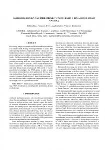
electrical grid emulator, a Hardware Test-Bed (HTB) is being developed that emulates large scale power system generators and loads by using power electronic converters. Source converters in the HTB system are designed to emulate generators. A synchronous generator model is implemented in the converter to calculate the voltage references in the dq axis, and a voltage controller is added to achieve zero steady state error. A traditional cascade controller with inner current control and outer voltage control brings additional output impedance to the generator model, and causes voltage tracking error during transients. To minimize the controller output impedance and eliminate controller influence on the generator model, a single voltage loop with current differential feedback is proposed in this paper. Combined with rescaled generator parameters, circulating current elimination, and dead time compensation, simulation and experiments are performed in the HTB. The results verify the effectiveness of the controller and demonstrate the dynamic generator emulator behavior. I.
INTRODUCTION
Transmission network emulator, also called Hardware Test-Bed (HTB), is conceptualized to emulate the large scale power system by interconnected converters which emulate power generators and loads. With modular and reconfigurable converters, the HTB can have flexible network and perform various scenario emulations. The HTB will allow testing, integration and demonstration of various key technologies on monitoring, control, actuation, and visualization. With HTB, it is also convenient to test different system architectures, such as HVDC vs. HVAC by reconfiguring the system structure. The impact of renewable energy sources, responsive loads, and energy storage to the power grid can also be evaluated [1]. A regenerative topology is adopted: converters are connected at both the AC and DC side with a rectifier at DC side, as
shown in Fig. 1. Because the power flows back and forth between AC and DC side, the total power consumed in steady state is only the converter loss. DC Bus Generattor I
Output Inductors
Grid Emulation
Generator II
Power Grid
Rectifier Load I
Load II
Fig. 1.
Hardware Test-Bed structure for the reconfigurable grid emulator.
Generator imitated converters have been proposed in Distributed Generators (DGs), where converters are generally applied as an interface with the power grid, to improve the system stability. Compared with traditional Synchronous Generators (SG), inverter interfaced DGs usually have fast dynamic response, but no inertia, which will cause frequency instability during a disturbance. To solve this problem, the concept of Virtual Synchronous Generator (VSG) which imitates the behavior of a SG has been proposed in [2]-[5]. The energy storage of DGs can be seen as virtual inertia: the mechanical power exchange is equivalent to the power exchange in a DC bus. Similar concepts have been developed in [6] as Synchroverter, [7] Static Synchronous Generator (SSG), and [8] Virtual Synchronous Machine. Reference [4] uses a Phase Locked Loop (PLL) to track the grid frequency, and regulates converter output power. Reference [6] uses converter output inductor and resistor to represent stator
inductance and resistance, thus the converter side voltage can be seen as back electromotive force (EMF), and the voltage of converter output capacitor can be seen as SG terminal voltage. SG model inside DSP does not generate any references, and the converter is governed by the excitation system and turbine of the SG model directly, like a real SG system. Reference [8] measures the voltage at the point of common coupling (PCC) and calculates current reference through the machine model. In the HTB, similar with island mode micro-grid, generators have to regulate the voltage and frequency to ensure the stability of the whole system. Each generator has its own frequency reference, and synchronization is realized through the active power and frequency droop. In this case, references [4] and [8] will not meet the requirement, since they assume that DGs are connected to a robust voltage source (infinite bus). Although reference [6] does not need any additional control besides SG model itself, stator inductance and resistance are fixed once one particular model is picked. In different power systems, generator parameters will vary too, and thus it is better to have virtual stator impedance. In this paper, system current is measured to generate the voltage reference by the SG model, and a voltage controller is then added to achieve zero steady state error. In voltage regulating inverters, such as Uninterruptible Power Supply (UPS) [1]-[11], grid connected inverters [12][15], and so on, cascade voltage outer loop and current inner loop are mostly applied. The inner current loop has fast dynamics and good transient response, and the outer voltage loop is applied to supply steady reference for the inner current loop. The design of the voltage loop is based on the transfer function of the small signal model of the system. But with only an L filter, the load model is involved in the voltage loop, and control parameters will be hard to derive. At the same time, unlike parallel converters, generators normally are very slow and do not have current control, thus they cannot be connected directly to the same bus. With only an L filter, voltages in the HTB will not be damped. But considering that PWM modulated output voltage pulses contain mostly switching frequency (usually larger than several kHz) and its n times harmonics, the control objectives-fundamental frequency signals-will not be affected by choosing proper control bandwidth. In this paper, a single voltage control loop with only an L filter is adopted. The major task of the converter is to behave exactly like a generator both in steady state and transient state. However the controller usually brings additional output impedance and changes the dynamic response of the generator emulator. To minimize the negative impact on the voltage control loop, it is necessary to reduce output impedance [16], or even obtain zero output impedance to achieve load invariant control [17][18]. Load current feed-forward is applied in [19], [20], and [21] to improve the transient performance during load change. In this paper, differential current feedback is applied to help minimize the converter output impedance. The rest of this paper is organized as follows: Part II introduces the electric and mechanical model applied in the SG emulator. Part III derives the equations to scale system parameters down to the HTB. Part IV investigates the voltage
controller of the generator emulator. Part V discusses the parallel operation of the converters, including circulating current elimination and dead time compensation. Part VI demonstrates the simulation and experiment results. II.
SYCHRONOUS GENERATOR MODEL
SG model has been established in many books [22][23]. The model used in the HTB in this research is a simplified two-axis model based on the following assumptions: 1.
The stator transients are neglected.
2.
During dynamic process, rotor speed is equal to synchronous speed.
3.
Saturation is not considered.
4.
Damping winding is only equipped on q-axis of the rotor.
A. Electric Model The electric model of the generator is then given by the equations:
(1)
and are d-axis and q-axis transient back EMF, where, and are the d-axis and q-axis transient reactance, and are termed the d-axis and q-axis transient open-circuit time constant, and are the d-axis and q-axis generator and are the d-axis and q-axis terminal stator currents, voltages which are used as converter references, is the field winding voltage. B. Mechanical Model The swing equation of the generator is given as: 1 where, is the rotor speed, is the synchronous speed, denotes the deviation of the rotor speed from synchronism, is electrical power, is the inertia is mechanical power, constant, is the damping factor caused by mechanical friction. Rotor angle δ is given to Park Transformation in the converter based generator emulator to convert the three phase signals onto and back from dq axis. The relationship between inertia constant M and H is given in (2) in per unit system, where is generator capacity, is the chosen base power.
·
(2)
A thermal turbine is chosen to model. Governor, droop control, Automatic Generation Control (AGC), Power System Stabilizer (PSS), and excitation system with Automatic
Voltage Regulator (AVR) are also included [23], as shown in Fig. 2 and Fig. 3. 1 Ms + D
Fig. 2.
Mechanical model of a synchronous generator.
In the excitation system shown in Fig. 3, is generator is the reference, and terminal voltage amplitude, are the gain and time constant of the excitation system. , which are determined by the reactive power and capacity of the generator, are the output boundaries for . KA Te s + 1
III.
SINGLE VOLTAGE LOOP WITH CURRENT DIFFERENTIAL FEEDBACK
1 s
The mechanical model is developed based on the assumption that the generator is running under steady state (synchronism) before a transient process caused by a small disturbance starts. Therefore, a proper controller should be adopted at the startup process of the HTB system, and mechanical part is not connected until steady state is reached.
Fig. 3.
IV.
Fig. 4.
Average model of a converter with current differential feedback.
Fig. 4 shows the average model of a converter system, d1 is converter duty cycle, I is AC side current, V is source inverter output voltage, L is converter output inductance, GLoad is the load converter impedance, Vdc is the DC voltage. Ignoring the digital controller time delay and the parasitic resistance in the inductor, the open loop control to output transfer function of the inverter is given by: (3) As we can see, to design the voltage controller, accurate load impedance GLoad is needed, and the load model is hard to get in a large and complicated system. In order to make the voltage loop independent of the load model, a current differential feedback is added in the system, as shown in Fig. 4. The open-loop control-to-output transfer function becomes:
Excitation model of a synchronous generator.
(4)
SYSTEM PARAMETERS RESCALING
In the power system, ratings of the generators and transmission lines are very large, normally hundreds of MW, and tens of kV, which cannot be realized in the experimental hardware emulation system. The system parameters need to be scaled down to the HTB ratings [24]. Base values of the generators and transmission line are different in the power system where transformers act as the interface. But in the HTB system, generator emulators are connected directly with the transmission line and the load, thus the real power system parameters should be converted to a common base first. Assume that the original system base values are , test-bed system base values are , and and scaling indexes are given as: /
,
/
,
, , . The
/
Thus the new impedance base will be: / Although the base values of the system change, p.u values stay the same, and the SG model is calculated in p.u model to avoid the redundant parameters’ rescaling process when the emulating system is more complex. For the per unit inertia constant H, we assume it does not change so that the mechanical part of the generator will have the same time constant during the transient process.
when H s
2Ls/V , the transfer function then becomes: V
V
(5)
Theoretically, through using this current differential feedback, the open loop control-to-output transfer function will be totally independent of load. But at the same time, the compensation effect depends largely on the current waveform, regarding that the differential function s in H(s) is very sensitive to the noise. Under this circumstance, a Low Pass Filter (LPF) is required on the differential feedback path. To simplify the system model, a first order LPF is adopted: HLPF 1/ τs 1 , where τ 1/ω , ω is the cutoff frequency. The open loop control to output transfer function then becomes: /
(6)
ω should be small enough to eliminate the noise, but at the same time, it should be large enough so that it will not constrain the compensation effect. Even though a real load invariant voltage loop cannot be achieved in practice, the transient load impact on the voltage loop can still be suppressed. The whole controller is shown in Fig. 5, where LPFV is the LPF for the voltage loop, and LPFI is the LPF for current differential feedback path. To minimize the steady state error
and improve dynamic response, a PI controller is added on the main path. Thus the bandwidth of the whole system is decided by both the PI controller and the voltage signal LPF.
TABLE I.
SYSTEM PARAMETERS USED IN THE TWO SIMULATIONS
Power Stage Parameters Sb=30kVA, Vbl-l=208V, L=0.5mH, Vdc=600V, f0=60Hz, fsw=10kHz, RLoad=5Ω
Control Parameters Control with current differential feedback
Cascade control
Kp1=0.8, Ki1=60 Kp2=0.008, Ki2=20
ω
Kp=0.0028, Ki=2 2 10 /
40
Fig. 5.
Magnitude (dB)
20
Proposed single voltage control loop with current differential feedback.
0 -20 -40 -60 90
Phase (deg)
Considering the fact that the prior task of the generator emulator is to make the converter behave exactly like a generator, it is necessary to investigate the influence of the additional voltage controller on the generator behavior.
45
0
-45 -1
0
10
1
10
2
10
3
10
4
10
5
10
10
Frequency (rad/s)
Fig. 6.
Converter output impedance with cascade controller. 0
Magnitude (dB)
-50 -100 -150 -200 -250 -300 270 225 Phase (deg)
Voltage source converters generally can be depicted by is the Input/Output characteristics in general as (7), where is the converter output dq converter voltage reference, is the converter output current, is the closed voltage, is the converter output impedance, loop voltage gain, and which is determined by both the system parameters and the controller. In a cascade outer voltage and inner current controller, considering that the voltage reference is constant, is given in (8), where is the voltage loop PI controller, is the current loop PI controller. and (7)
180 135
(8)
90 -1
10
0
1
10
10
2
3
10
4
10
5
10
10
Frequency (rad/s)
As shown in part II, the voltage reference is a function of system current , , where is the generator model output impedance. Combine the equation with (7): (9) The controller will introduce additional output impedance and change the generator emulator behavior. is determined by many factors, including the In (8), parameters of the two PI controllers, and it is tedious to find the optimized controller to achieve minimum impedance.
Fig. 7.
Converter output impedance with proposed controller.
Simulation with the parameters described in TABLE I is performed in Matlab/Simulink using the cascade controller and the proposed controller respectively. As shown in Fig. 10, Inverter 1 is implemented with a generator model, and inverter 2 is emulating a 5 Ω resistive load which connects at t=0.2 s. With the cascade controller, as shown in Fig. 8, when the load connects, converter output voltages have significant oscillation and sag. In comparison, the proposed controller, as shown in Fig. 9, can track the voltage references perfectly. 300
Compared with the cascaded control loop, the converter output impedance with current differential feedback is given as:
250
Vdref Vqref
200
Vdfbk Vqfbk
150 100
(10)
50 0
where is the PI controller. When ω is large enough, approaches 0. To demonstrate the influence of the controller, a constant impedance load is adopted. The system parameters are given in Table I, and the bode plots of under the two different controllers are shown in Fig. 6 and Fig. 7 respectively. The impedance of the proposed controller is much smaller than the traditional controller in the frequency range of interest, and therefore the impact of the controller on the emulator characteristics can be minimized.
-50 -100 0
Fig. 8.
0.05
0.1
0.15
0.2
0.25
0.3
0.35
0.4
0.45
0.5
Converter voltage reference and feedback in dq axis with cascade controller.
Based on the circuit topology, an average model of the system in dq0 axis can be obtained, as shown in Fig. 11. 1 , is the inverter 1 duty cycle in dq0 axis; 2 , is the inverter 2 duty cycle in dq0 axis; is DC side voltage; I =[Id, Iq, I0]T is average AC side current in dq0 axis. Each inverter has its own reference frame, thus to better analyze the whole system, inverter 1’s Park transformation is chosen to be the common reference.
300 Vdref Vqref Vdfbk Vqfbk
250 200 150 100 50 0 -50 -100 0
Fig. 9.
0.05
0.1
0.15
0.2
0.25
0.3
0.35
0.4
0.45
0.5
Converter voltage reference and feedback in dq axis with proposed controller.
By studying the average model of the converter, it could be discovered that, the introduction of current differential feedback will increase the transient impact on DC current. 1
V.
PARALLEL OPERATION OF THE CONVERTERS
A. Average Model The converters in the HTB are connected in parallel at both AC and DC side. In this paper, the system with one generator and one load emulator is investigated first, as shown in Fig. 10. Inverter 1 regulates output voltage and frequency, and inverter 2 regulates the output current and uses PLL to follow the system frequency.
(11)
And the DC side current becomes: (12) 0, In steady state, . And the rectifier output DC side current is obtained by (13), which shows that in steady state, the rectifier only needs to supply the power consumed on the parasitic resistance in the inductors and the converter loss. (13) During transient state, the controller transfers load change influence on the voltage loop in AC side to the DC current, and will experience fluctuation. Thus a robust DC power source is required. With the same simulations performed in part IV, Figs. 12 and 13 show the DC side average current per switching period with different control strategies. In the proposed controller, DC side current will suffer a larger oscillation during transient state. 15
Fig. 10.
System with two inverters connected in parallel.
10
In the above system, S1=[Sa1, Sb1, Sc1]T and S2=[Sa2, Sb2, Sc2]T are switching functions of the two inverters, I =[ia, ib, ic]T is AC side current, V1=[va1, vb1, vc1]T and V2=[va2, vb2, vc2]T are inverter 1 and 2 output voltages, V=[va, vb, vc]T is the connection point voltage, L is converter output inductance, R is inductor parasitic resistance, and idc, idc1, and idc2 are DC side currents.
5
0
-5
-10
-15 0
Fig. 12. Inverter 1: Generator
dd1Vdc
R
L
Id ωgLIq Vd
R
L
Iq ω LI g d Vq
Idc Idc1 dd1Id dq1Iq d01I0
0.1
0.15
0.2
0.25
0.3
0.35
0.4
0.45
0.5
Average DC side current with cascade controller when the load connects at t=0.2 s. 15
dq1Vdc
Vdc
0.05
R d01Vdc
L
R
L
10
5
I0
0
Idc2
dd2Vdc
ωgLIq
-5
dd2Id dq2Iq d02I0 R
L
d02VdcR
L
dq2Vdc
-10
ωgLId
-15 0
Inverter 2: Load
Fig. 11.
Average model of the system in dq0 axis.
Fig. 13.
0.05
0.1
0.15
0.2
0.25
0.3
0.35
0.4
0.45
0.5
Average DC side current with proposed controller when the load connects at t=0.2 s.
B. Circulating Current One of the major problems that the parallel topology will encounter is zero sequence circulating current between the converters [25][26]. The circulating current consists two parts: one part contains mainly switching frequency components. When the parallel converters have the same modulation waveform but unsynchronized carrier waveforms, the switching positions of the converters will be different, which results in the different closed path between the converters when they have a common DC link. The other part is the long time period current caused by the non-identical converter parameters. Although the circulating current does not affect the control objectives, it will cause current distortion and , the average unbalance. As shown in Fig. 11, when model of zero sequence current (long time period) is obtained by: 2
2
inverter 1 voltage reference in dq axis is [50 0]TV. Inverter 2 current reference changes from [0 10]TA to [0 20]TA. Experimental data is analyzed in Matlab/Simulink, where a LPF with 1 kHz cutoff frequency is applied for the voltage signal, as shown in Fig. 14(b). Inverter 1 uses the proposed controller, and as we can see, a load step change only causes a minor disturbance on the output voltage waveform (line to line). At the same time, Inverter 1 and 2 have dead time compensation and zero sequence current control, and THD for the current in Fig. 14 before and after load change are 3.78% and 2.5%, respectively. After verifying the voltage controller for generator emulator, SG model is implemented in the Texas Instrument DSP TMS320F28335. The parameters of SG model are given in TABLE II, and the power ratings and controller parameters of generator emulator are shown in TABLE III.
(14)
Vab
To eliminate the circulating current, the following methods have been used: Common mode choke which can provide high zero sequence impedance, and synchronized carrier waveforms are applied to constrain switching frequency components. PI controller on zero sequence current is adopted to eliminate long time period components.
Ia
C. Dead Time Compensation Dead time is used in the PWM modulation to avoid a short circuit of the upper and lower part of the same bridge. Although the dead time is usually very small, which is around a couple of microseconds, compared with the switching period in high switching frequency converters, it is large enough to cause output voltage distortion [27].
(a) Experimental results (I: 10A/5V). 100
Vab (V)
50
Traditionally, pulse by pulse compensation is applied through adding or subtracting dead time to the pulse width according to the polarity of the current. This method requires highly accurate detection of the current, otherwise, the noise will cause under or over compensation, and thus exacerbate the problem. For the current regulated inverter 2, a pure three phase sine wave can be generated according to the current references and the Park Transformation phase angle, assuming that the current controller achieves zero steady state error. This sine wave can substitute the detected current in order to get the exact zero crossing point. For the voltage regulated inverter 1, and to as discussed in part IV, LPFs will be added on reconstruct the three phase current, since there are not any current references. VI.
EXPERIMENTAL RESULTS
Experiments are performed using the topology shown in Fig. 10. The output inductance of inverter 1 and 2 are 2.5 mH and 1 mH respectively. Inverter 2 regulates output current and adopts a normal PI controller. Fig. 14(a) demonstrates the dynamic experimental output voltage of inverter 1 during load change controlled by inverter 2. In the experiment, the common DC side voltage is 120 V,
0 -50 -100 20
Ia (A)
10 0 -10 -20
0.1
0.105
0.11
0.115
0.12
0.125
0.13
Time (s)
(b) Analysis of the experimental data in Matlab with 1 kHz LPF on the voltage signal. Fig. 14.
Experimental results of load change influence on the voltage loop with proposed controller. GENERATOR PARAMETERS
TABLE II. Mechanical 6.5,
200, droop=20,
TABLE III. Power Stage Parameters Vbl-l=120V, Ib=30A, Vdc=300V, f0=60Hz, fsw=10kHz,
Electrical 0.01,
1.8, 0.55,
1.7, 8 ,
0.3, 0.4
POWER STAGE AND CONTROLLER PARAMETERS Control Parameters Generator Emulator
Load Emulator
Kp=0.0064, Ki=4 ω 2 10 /
Kp=0.06, Ki=10
Vab
Vab
Ia
Ia
(b) Experimental results with load step down (I: 10A/5V).
200
200
100
100
Va (V) Vab (V)
Vab (V) Va (V)
(a) Experimental results with load step up (I: 10A/5V).
0
0
-100
-100
-200
-200
30
40
20
20
Ia (A)
Ia (A)
10 0 -10
0
-20
-20 -30
-40
0.28
0.3
0.32
0.34
0.36
0.38
0.48
0.4
0.49
0.5
0.51
(c) Analysis of the experimental data in Matlab with 1 kHz LPF on the voltage signal during load step up.
0.55
0.56
0.57
0.58
Rotor Speed (rad/s)
381
380 375 370
380 379 378 377
365
376
3000
4000
Output Power (W, Var)
Rotor Speed (rad/s) Output Power (W, Var)
0.54
(d) Analysis of the experimental data in Matlab with 1 kHz LPF on the voltage signal during load step down.
385
2500
P
2000
Q
1500 1000 500 0
3000
P
2000
Q 1000 0
100
100
Output Voltage (V)
Output Voltage (V)
0.53
Time (s)
Time (s)
50
Vq 0
Vd -50 -100
0.52
s
s
1
2
3
4
5
6
7
8
9
10
50
Vq 0
Vd -50 -100
0
1
2
3
s
4
5
6
7
8
9
10
s Time (s)
Time (s)
(e) Generator rotor speed, output power and terminal voltages during load step up. Fig. 15.
(f) Generator rotor speed, output power and terminal voltages during load step down.
Experiment with one generator and one load emulator.
As shown in Fig. 15(a) and (b), experiments with load step up and down are performed. Inverter 2 current references change from [0 20]TA to [0 25]TA, and [0 30]TA to [0 25]TA respectively in the two experiments. Output voltage and system current signals are investigated in Matlab. Just as with previous experiment, a 1 kHz LPF is adopted for the voltage
waveform. As shown in Fig. 15(c) and (d), the voltage waveforms are unaffected by the load change. To further demonstrate the generator behavior, data are read from the DSP with sampling period 0.02s. Rotor speed, output power and terminal voltages in dq-axis of the generator emulator during dynamic process are shown in Fig. 15(e) and (f).
During load step up/down, rotor speed decreases/increases, and because of AGC, it regains synchronous value slowly. Terminal voltages also change slightly according to the system current. VII. CONCLUSION This paper has investigated the methods to emulate a synchronous generator in a converter consisted HTB system. A simple two axis model is adopted to calculate the terminal voltage references for the converter, and a voltage controller is then added to obtain zero state error. Based on the converter topology, a single voltage controller with current differential feedback has been proposed to compensate the load disturbance on the output voltage. The controller has minimized output impedance, and thus has small tracking error. Simulation and experiment have verified the effectiveness of the controller and demonstrated the generator emulator behavior during load change by implementing it into the hardware test-bed system Based on this work, power system emulation with multiple generators, variable loads and transmission line will be established in the next step.
[8]
[9]
[10]
[11]
[12]
[13]
[14]
[15]
[16]
ACKNOWLEDGMENT This work was supported primarily by the Engineering Research Center Program of the National Science Foundation and the Department of Energy under NSF Award Number EEC-1041877 and the CURENT Industry Partnership Program.
[17]
[18]
[19]
REFERENCES [1]
[2] [3]
[4]
[5]
[6]
[7]
J. Wang, L. Yang, Y. Ma, X. Shi, X. Zhang, L. Hang, and et al., “Regenerative power converters representation of grid control and actuation emulator,” IEEE Energy Conversion Congress and Exposition (ECCE), Sep. 2012, pp. 2460–2465. J. Driesen and K. Visscher, “Virtual synchronous generators,” Proc.IEEE Power Energy Soc. Gen. Meeting, Jul. 2008, pp. 1–3. T. Vu Van, K. Visscher, J. Diaz, V. Karapanos, A. Woyte, and et al., “Virtual synchronous generators: An element of future grids,” IEEE PES Innovative Smart Grid Technologies Conference Europe (ISGT Europe), Oct. 2010, pp. 1–7. K. Sakimoto, Y. Miura, and T. Ise, “Stablization of a power system with a distributed generator by a virtual synchronous generator function,” IEEE International Conference on Power Electronics and ECCE Asia, Jun. 2011, pp. 1498–1501. V. Thong, A. Woyte, M. Albu, M. Hest, J. Bozelie, J. Diaz, T. Loix, D. Stanculescu, and K. Visscher, “Virtual synchronous generator: Laboratory scale results and field demonstration,” Proceedings of the IEEE Powertech Conference, Jun.-Jul. 2009, pp.1–6. Q. Zhong, and G. Weiss, “Synchronverters: inverters that mimic synchronous generators,” IEEE Transactions on Industrial Electronics, vol. 58, no. 4, pp. 1259–1267, Apr. 2011. Q. Zhong and G. Weiss, “Static synchronous generators for distributed generation and renewable energy,” IEEE/PES Power System Conference and Exposition, Mar. 2009, pp. 1–6.
[20]
[21]
[22] [23] [24]
[25]
[26]
[27]
H. Beck, and R Hesse “Virtual synchronous machine,” 9th International Conference on Electric Power Quality and Utilisation, Oct. 2007, pp. 1–6. M. J. Ryan, W. E. Brumsickle, and R. D. Lorenz, “Control topology options for single-phase UPS inverters,” IEEE Transactions on Industry Applications, vol. 33, no. 2, pp. 493–501, Mar/Apr. 1997. G. Willmann, D. F. Coutinho, L. F. A. Pereira, and F. B. Líbano, “Multiple-loop H-infinity control design for uninterruptible power supplies,” IEEE Transactions on Industrial Electronics, vol. 54, no. 3, pp. 1591–1602, Jun. 2007. P. Mattavelli, F. Polo, F. D. Lago, and S. Saggini, “Analysis of controldelay reduction for the improvement of UPS voltage-loop bandwidth,” IEEE Transactions on Industrial Electronics, vol. 55, no. 8, pp. 2903– 2911, Aug. 2008. Z. Yao, and L. Xiao, “Control of single-phase grid-connected inverters with nonlinear loads,” IEEE Transactions on Industrial Electronics, no. 99, pp. 1–6, 2011. S. Park, J. Lai, and W. Lee, “An easy, simple, and flexible control scheme for a three-phase grid-tie inverter system,” IEEE Energy Conversion Congress and Exposition (ECCE), 2010, pp. 599–603. Z. Wang, C. Xie, C. He, and G. Chen, “A waveform control technique for high power shunt active power filter based on repetitive control algorithm,” IEEE Applied Power Electronics Conference and Exposition (APEC), 2010, pp. 361–366. Z. Wang, C. Xie, J. Zhang and G. Chen, “Dynamic DC-bus voltage control strategies for a three-phase high power shunt active power filter,” IEEE Applied Power Electronics Conference and Exposition (APEC), 2010, pp. 1514–1520. H. Deng, R. Oruganti, and D. Srinivasan, “A simple control method for high-performance UPS inverters through output-impedance reduction,” IEEE Transactions on Industrial Electronics, vol. 55, no. 2, pp. 888– 898, Feb. 2008. L. D. Varga and N. A. Losic, “Synthesis of zero-impedance converter,” IEEE Transactions on Power Electronics, vol. 7, no. 1, pp. 152–170, Jan. 1992. M. Stanojevic, and M. Stefanovic, “A UPS inverter with zero output impedance,” IEEE International Conference on Industrial Electronics, Control and Instrumentation (IECON), 1994, pp. 469–472. N. A. Losic, L. D. Varga, and Z. D. Popovic “Generalized synthesis and applications of zero-impedance converter and its dual,” IEEE Transactions on Circuits and Systems-I: Fundamental Theory and Applications, vol. 46, no. 11, pp. 1349–1359, Nov. 1999. M. Karppanen, M. Hankaniemi, T. Suntio, and M. Sippola, “Dynamical characterization of peak-current-mode-controlled buck converter with output-current feedforward,” IEEE Transactions on Power Electronics, vol. 22, no. 2, pp. 444–451, Mar. 2007. M. Hankanieml, T. Suntio, and S. Ruotsalainen “Load invariant buck converter -analysis and implementation,” European Conference on Power Electronics and Applications, 2005, pp. 1–10. P. C. Krause, Analysis of Electric Machinery. New York: McGrawHill, 1986. P. Kundur, Power System Stability and Control. New York: McGrawHill, 1994. V. C. Strezoski, “New scaling concept in power system analysis,” IEE Proceedings on Generation, Transmission and Distribution, vol. 143, no. 5, pp. 399–406, Sep. 1996. Z. Ye, D. Boroyevich, J. Choi, F. C. Lee “Control of Circulating Current in Two Parallel Three-Phase Boost Rectifiers,” IEEE Transactions on Power Electronics, vol. 19, no. 5, pp. 609–615, Sep. 2002. C. Pan, and Y. Liao, “Modeling and coordinate control of circulating currents in parallel three-phase boost rectifiers,” IEEE Transactions on Industrial Electronics, vol. 54, no. 2, pp. 825–838, Apr. 2007. A. C. Oliveira, C. B. Jacobina, and A. M. N. Lima, “Improved deadtime compensation for sinusoidal PWM inverters operating at high switching frequencies,” IEEE Transactions on Industrial Electronics, vol. 54, no. 4, pp. 2295–2304, Aug. 2007.