materials Article
Reactive Fabrication and Effect of NbC on Microstructure and Tribological Properties of CrS Co-Based Self-Lubricating Coatings by Laser Cladding Liuyang Fang 1,2 , Hua Yan 1,2, *, Yansong Yao 1,2 , Peilei Zhang 1,2 , Qiushi Gao 1,2 and Yang Qin 1,2 1
2
*
School of Materials Engineering, Shanghai University of Engineering Science, Shanghai 201620, China;
[email protected] (L.F.);
[email protected] (Y.Y.);
[email protected] (P.Z.);
[email protected] (Q.G.);
[email protected] (Y.Q.) Shanghai Collaborative Innovation Center of Laser Advanced Manufacturing Technology, Shanghai University of Engineering Science, Shanghai 201620, China Correspondence:
[email protected]; Tel.: +86-21-6779-1412
Received: 6 December 2017; Accepted: 26 December 2017; Published: 28 December 2017
Abstract: The CrS/NbC Co-based self-lubricating composite coatings were successfully fabricated on Cr12MoV steel surface by laser clad Stellite 6, WS2 , and NbC mixed powders. The phase composition, microstructure, and tribological properties of the coatings ware investigated by means of X-ray diffraction (XRD), scanning electron microscopy (SEM), and energy dispersive spectrometer (EDS), as well as dry sliding wear testing. Based on the experimental results, it was found reactions between WS2 and Co-based alloy powder had occurred, which generated solid-lubricant phase CrS, and NbC play a key role in improving CrS nuclear and refining microstructure of Co-based composite coating during laser cladding processing. The coatings were mainly composed of γ-Co, CrS, NbC, Cr23 C6 , and CoCx . Due to the distribution of the relatively hard phase of NbC and the solid lubricating phase CrS, the coatings had better wear resistance. Moreover, the suitable balance of CrS and NbC was favorable for further decreasing the friction and improving the stability of the contact surfaces between the WC ball and the coatings. The microhardness, friction coefficient, and wear rate of the coating 4 (Clad powders composed of 60 wt % Stellite 6, 30 wt % NbC and 10 wt % WS2 ) were 587.3 HV0.5 , 0.426, and 5.61 × 10⁻⁵ mm3 /N·m, respectively. Keywords: laser cladding; metal matrix self-lubricating coating; microstructure; tribological behavior
1. Introduction The lubricating and tribological property of moving components under extreme conditions such as high temperature, heavy load, vacuum, and humid and dry air environments seriously affect their reliability and service time of the entire system [1,2]. However, traditional oils or other liquid lubricants easy fail in these severe conditions [3]. The metal matrix self-lubricating composites are highly desirable for their remarkable properties [1,4]. Those materials possess a low friction coefficient and good wear resistance under the condition of lubricant failure or no lubrication media, and have been successfully used in aerospace systems, steam turbines, and industrial drying furnaces [1,4–7]. In general, metal matrix self-lubricating materials are utilized in a form of coating instead of bulk composite, since the friction/wear always takes place on work-piece surfaces [8], and various surface modification techniques can be employed to produce metal matrix self-lubricating coatings (MMSCs), such as plasma spraying [9,10], electroplating [11,12], physical vapor deposition [13], and laser cladding [14,15], among which laser cladding is very effective
Materials 2018, 11, 44; doi:10.3390/ma11010044
www.mdpi.com/journal/materials
Materials 2018, 11, 44
2 of 13
and offers distinct advantages such as lower porosity, a narrow heat-affected zone, and strong metallurgical bonding. As a well-known solid lubricant, WS2 has a lamellar structure much like MoS2 and graphite, is easily used to form transfer lubricious films between the friction pair interface, and is used as a solid lubricant additive. However, previous research [14,16,17] has shown that WS2 decomposed and oxidized when it was used as solid lubricant additives to fabricate MMSCs by laser cladding. In order to overcome the difficulties, many attempts have been tried to inhibit its decomposition. Wang et al. [16] reported the high-energy ball milling method to encapsulate nano-Ni onto submicron WS2 to prevent the mass loss of WS2 during laser cladding. Liu et al. [17] applied the electroplating technique that encapsulated WS2 with a layer of micro Ni-P to inhibit its decomposition during the laser cladding process. Although the encapsulating methods and optimization of the laser cladding process parameters could have decreased the decomposition of WS2 to some extent, there was still a lot of WS2 decomposed and vaporized during the laser cladding processing. These problems weaken the performance of laser clad self-lubricating coating. Recently, the solid-lubricant phase was synthesized using the high-energy method that shows promise for producing MMSCs [8,18–20], which could avoid the decomposition and oxidization of lubricants [8]. Skarvelis et al. [18] fabricated a MMSC containing TiS and Ti4C2 S2 on AISI 1522H plain steel substrate by plasma transferred arc of TiS2 and TiC powder mixture. Results showed that the formation of TiS and Ti4C2 S2 in the coating was beneficial to the coating’s tribological properties. Lu et al. [19] fabricated the Ti2 CS/CrS MMSC by laser clad NiCr/Cr3 C2 -WS2 mixed powders; the results indicated that the composite coating presented excellent self-lubricating properties due to the formation of the lubricious CrS and Ti2 CS sulfides. Among those studies, the friction-reducing role of self-lubrication phases (such as TiS, Ti2 CS, and CrS) has been investigated in detail and the formation mechanism of CrS is also involved. It is worth mentioning that the above researches do not consider the effect of ceramic particles on the formation mechanism of CrS. Moreover, the comprehensive effect of CrS and ceramic particles on the wear mechanism also needs to be revealed. In the present study, the objective is focusing on the reaction synthesis that fabricates the self-lubricating composite coating that contains solid-lubricant phase CrS, as well as exploring the idea that ceramic particles contribute to improving the microstructural evolution of the coating. Besides, the tribological behavior of the coatings was also explored. Here, a novel method was developed to fabricate the coating that contains CrS and ceramic particles. Co-based alloy powder (Stellite 6) was introduced into laser cladding, together with WS2 and NbC. WS2 was selected to synthesize CrS with Stellite 6, while the ceramic particle of NbC was selected to reinforce the coating and improve CrS formation. For comparison, the Stellite 6, WS2 /Stellite 6, and NbC/Stellite 6 coatings were also prepared by laser cladding. The microstructure and wear performance of those coatings are presented and discussed. 2. Materials and Methods 2.1. Materials Flat plate of unheated-treated Cr12MoV steel with the dimension of 50 mm × 50 mm × 10 mm was selected as substrate. According to Xiao-Long Lu’s [19] research, WS2 is easily decomposed to form S and W elements during laser cladding due to its low decomposition temperature, in which S can react with Cr to form CrS in the molten pool . In addition, Stellite 6 is a common Co-based alloy powder with a high Cr content, which is favorable for the reaction to form CrS. Therefore, we select Stellite 6 as metal matrix to synthesize CrS with WS2 . As a common hard alloy additive, NbC possesses high melting point (~3600 ◦ C), high hardness (~19.6 GPa), and a density of 7.79 g/cm3 (which is close to Co, ~8.9 g/cm3 ) [21]; because of these advantages, NbC was selected as additive with the purpose of improving CrS formation and refining the microstructure of the metal matrix. In the present research, Co-based alloy powder (Stellite 6, powder size: about 75 µm), WS2 (particle size: 0.5–1 µm), and NbC
Materials 2018, 2018, 11, 11, 44 44
3 of 13 14
composition of substrate and Stellite 6 were listed in Table 1. In order to better explore the (particle size: 1–3 µm) were usedcoatings, as cladding materials.materials The chemical composition of substrate and6 microstructure evolution of the the cladding were made as mixtures of Stellite Stellite 6 were listed in Table 1. In order to better explore the microstructure evolution of the coatings, with different contents of WS2 and NbC. The mixtures’ composition for coatings was illustrated in the cladding materialswere weredried madeatas80mixtures Stellite with different contents of WS2 and Table 2. The mixtures °C for 30ofmin prior6 to being ground in a mechanical ballNbC. mill ◦ C for The mixtures’ composition for coatings was illustrated in Table 2. The mixtures were dried at 80 for 2 h to ensure a uniform dispersion. 30 min prior to being ground in a mechanical ball mill for 2 h to ensure a uniform dispersion. Table 1.Chemical composition of substrate and Stellite 6. Table 1. Chemical composition of substrate and Stellite 6.
Material Material C Substrate SubstrateStellite 1.616 Stellite 6
1.15
Element (wt %) %) C Cr Si W Element Mo (wtNi Mn V Co Fe Cr Si W Mo Ni Mn V Co 1.61 12.02 0.23 0.52 0.09 0.14 0.22 Bal. 12.02 29.00 0.23 1.10 - 4.00 0.52 0.14 1.15 1.00 0.09 3.00 0.05 - 0.22 Bal. -3.00 29.00
1.10
4.00
1.00
3.00
0.05
-
Bal.
Fe Bal. 3.00
Table 2. Mixtures composition for coatings. Table 2. Mixtures composition for coatings.
Number Number
Coating 1 Coating Coating 12 Coating 23 Coating Coating 3 Coating Coating 44 Coating Coating 55 Coating 66 Coating
Mixtures Composition (wt %) Mixtures (wt %) Stellite 6 Composition WS2 NbC 100 6 - 2 Stellite WS NbC 85 15-100 7085 - 15 30 70 30 6060 1010 3030 5555 1515 3030 5050 2020 3030
2.2. Laser Cladding Prior to laser cladding, the mixed powder needs to be prepared on on the the substrate. substrate. The bonding method is very simple and flexible, and and commonly commonly used used to to prepare prepare the the preplaced preplaced layer layer [22]. [22]. However, the binder used in the method may be decomposed to other elements and pollute the method decomposed coating during laser cladding. In order to solve the shortcoming mentioned above, mixed powder was preplaced on substrate without using the binder. The preplace process is illustrated in Figure 1 and the thickness of preplaced layer was was controlled controlled by by about about 1.5 1.5 mm. mm. Laser cladding was carried out using a IPG-YLS-5000 fiber laser system in a novel gas protection device, and the laser cladding process Figure 2. The optimized parameters utilized in the in experiments are as follows: process isisillustrated illustratedinin Figure 2. The optimized parameters utilized the experiments are as − 1 −1 laser power 2.5power KW, scanning 12.5 mm ·s 12.5 , andmm·s spot diameter 3 mm. Argon 3was selected the follows: laser 2.5 KW,speed scanning speed , and spot diameter mm. Argonaswas −1 . The protective protective a flow gas ratewith 10 L·amin gas was switched three seconds selected asgas thewith protective flow rate 10 L·min−1. The protective gason was switched onbefore three laser cladding until procedure three seconds theseconds procedure Then the single track seconds beforeprocedure laser cladding untilafter three afterfinished. the procedure finished. Thenand the overlapped with an coatings overlap rate were rate cooled in air. single track coatings and overlapped withofan40% overlap of 40% were cooled in air.
Figure 1. Schematic powders on on substrate. substrate. Figure 1. Schematic of of preparation preparation powders
Materials 2018, 11, 44 Materials 2018, 11, 44
4 of 13 4 of 14
Materials 2018, 11, 44
4 of 14
Figure 2. 2. Schematic of laser laser cladding cladding process. process. Figure Schematic of Figure 2. Schematic of laser cladding process. 2.3. Microstructure Characterization 2.3. Microstructure Characterization
2.3. Microstructure The cross section sectionCharacterization specimens of of the the coated coated samples samples were were prepared prepared perpendicular perpendicular to to the the single single The cross specimens track with a wire cutting machine, then processed by a standard metallographic procedure, and cross cutting section specimens the coated samples were prepared perpendicular to the single and track withThe a wire machine,ofthen processed by a standard metallographic procedure, finally eroded in a mixed solution (volume ration of HNO 3 :HCl: CH 3 COOH:H2O = 1:4:1:1) for 90 track within aa wire cutting machine, then processed by a standard metallographic procedure, finally eroded mixed solution (volume ration of HNO = 1:4:1:1)and for 90 s. s. 3 :HCl: CH 3 COOH:H2O The microstructure and element distribution was characterized by scanning electron micro-scope finally eroded in a mixed solution (volume ration of HNO 3:HCl: CH 3COOH:H2O = 1:4:1:1) for 90 s. The microstructure and element distribution was characterized by scanning electron micro-scope microstructure Tokyo, and element distribution was characterized by scanningspectrometer electron micro-scope (SEM,The Hitachi/S-3400, equipped with an an energy dispersive (EDS). The (SEM, Hitachi/S-3400, Tokyo,Japan) Japan) equipped with energy dispersive spectrometer (EDS). (SEM, Hitachi/S-3400, Tokyo, Japan) equipped with an energy dispersive spectrometer (EDS). The crystal phases of coatings were identified by X-ray diffraction (XRD, PANalytical/X’Pert Pro, EA The crystal phases of coatings were identified by X-ray diffraction (XRD, PANalytical/X’Pert Pro, crystal phases of coatings were identified by X-ray diffraction (XRD, PANalytical/X’Pert Pro, EA Almelo, TheThe Netherlands). Surface morphology of of the scanning EA Almelo, Netherlands). Surface morphology thewear wearscars scarswas wascharacterized characterized by by scanning Almelo, The Netherlands). Surface morphology of the wear scars was characterized by scanning electron microscope (SEM). electron microscope (SEM). electron microscope (SEM).
Test 2.4. Microhardness andand Wear Test 2.4. Microhardness Wear Test The microhardness microhardness along the of was coating wasmeasured measured by a Vickers The along the depth direction of coating measured by a Vickers The microhardness along the depth depth direction direction of coating was by microhardness a Vickers microhardness tester (HXD-1000TMSC/LCD, Guangzhou, agfload ofa 500 gf and aof dwell microhardness tester (HXD-1000TMSC/LCD, Guangzhou, a load of 500 gf and a dwell tester (HXD-1000TMSC/LCD, Guangzhou, China) with China) aChina) load with ofwith 500 and dwell time 15s; time of 15s; the microhardness was measured repeatedly and average was adopted. The dry sliding time of 15s; the microhardness was measured repeatedly and average was adopted. The dry sliding the microhardness was measured repeatedly and average was adopted. The dry sliding friction test was friction test was carried out pin-on-disc friction and testing machine (Bruker/UMT-3, friction teston was carried outfriction onona apin-on-disc friction andwear wear testing machine (Bruker/UMT-3, carried out a pin-on-disc and wear testing machine (Bruker/UMT-3, Baden-Württemberg, Baden-Württemberg, Germany) in air for 30 min. The schematic diagram of friction andand wear was was Baden-Württemberg, air for 30 min. The schematic diagram of friction Germany) in air for 30Germany) min. The in schematic diagram of friction and wear was illustrated inwear Figure 3. illustrated in Figure 3. The counter-body was a WC ball with a diameter of 9.5 mm and a hardness illustrated in Figure 3. The counter-body was a WC ball with a diameter of 9.5 mm and a hardness The counter-body was a WC ball with a diameter of 9.5 mm and a hardness of 1700 HV. The applied of 1700 HV. The applied load was 10 kg and the sliding radius was 3 mm. The wear volumes of the of 1700 HV. Theand applied load was 10 kg and the sliding radius was 3of mm. wearwere volumes of the load was 10 kg the sliding radius was 3 mm. The wear volumes the The coatings measured coatings were measured using an optical microscopy (OM, KEYENCE/VHX-5000, Osaka, Japan). coatings were measured using an optical microscopy (OM, KEYENCE/VHX-5000, Osaka, Japan). usingThe anwear optical (OM,with KEYENCE/VHX-5000, Osaka, Japan). The wear rare W was raremicroscopy W was calculated the formula below: The wear rare was calculated with the formula below: calculated withWthe formula below: V V (1) W W= = V (1) LS W= (1)
3 LS thetotal wherewhere V is the volume (mm totalsliding sliding distance load(N) (N) and and SSisisthe distance (m).(m). V is wear the wear volume (mm),3),L Lisisload
where V is the wear volume (mm3), L is load (N) and S is the total sliding distance (m).
Figure 3. Schematic of wear test. Figure 3. Schematic of wear test.
Figure 3. Schematic of wear test.
Materials 2018, 11, 44 Materials 2018, 11, 44
5 of 13 5 of 14
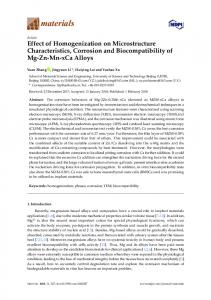
3. 3. Results Results and and Discussions Discussions 3.1. XRD Results 1 (Stellite 6) 6) is The XRD patterns patterns of of the the coatings coatingsare areshown shownininFigure Figure4.4.ItItwas wasfound foundthat thatcoating coating 1 (Stellite mainly comprised ofof γ-Co, CoC CC6 6. . When is mainly comprised γ-Co, CoC , andCrCr When 15 15 wt wt % % WS WS22 is added in Stellite 6, some new x , xand 2323 ◦ , 33.8°, 33.8◦ , and and 53.4°are 53.4◦ are found found in coating 2. They They are are conformed conformed as as the peaks of peaks located at 29.8 29.8°, in terms terms of of the the relevant relevantJCPDS JCPDScard card(No. (No.03-065-9010 03-065-9010forfor CrS). When NbC is added CrS in CrS). When 3030 wtwt %% NbC is added in ◦ , 40.4 ◦ , 58.5 ◦ are found in Stellite 6, some other peaks located at 34.8 and 69.9found in coating 3. Stellite 6, some other newnew peaks located at 34.8°, 40.4°, 58.5°, and◦ , 69.9°are in coating 3. They They are conformed the peaks ofin NbC in terms the relevant card03-067-7964 (No. 03-067-7964 for are conformed as theas peaks of NbC terms of the of relevant JCPDSJCPDS card (No. for NbC). NbC). Compared with the data XRD of data of in CrSRef. in Ref. NbC Ref. [23],ititcan canbe be deduced deduced that Compared with the XRD CrS [19][19] andand NbC in in Ref. [23], CrS, and and NbC. Comparing coating 4, coating 5, and coating coating 66 mainly mainly consists consists of ofγ-Co, γ-Co,CoC CoCxx,, Cr Cr23 23C66,, CrS, coating 3, and coating 5, it 5, is indicated that NbC exist inexist the coating XRD patterns patternsofofcoating coating1, 1, coating 3, and coating it is indicated that remain NbC remain in the during laser cladding process. However, no WS2 phase can2 be found in be XRD analysis. It indicates that coating during laser cladding process. However, no WS phase can found in XRD analysis. It WS decomposed into W and S elements during laser cladding process, in which S reacted with the indicates that WS 2 decomposed into W and S elements during laser cladding process, in which S 2 melting with Cr tothe form CrS in Cr thetomolten poolin [19]; CrSpool appears the coating 2, coating coating 2, 5, reacted melting form CrS thethus, molten [19];in thus, CrS appears in the4,coating and coating 6. coating 4, coating 5, and coating 6.
Figure Figure 4. 4. XRD XRD (X-ray (X-ray diffraction) diffraction) patterns patterns of of the the coatings. coatings.
3.2. 3.2. Microstructure Microstructure of of the the Coatings Coatings Typical SEM micrographs micrographs of the coatings coatings are are shown shown in in Figure Figure 5. 5. It Typical SEM of the It has has been been observed observed that that the the microstructure of the coating 1 was mainly composed of network dendritic structure and column microstructure of the coating 1 was mainly composed of network dendritic structure and column -like -like crystals (Figure 5a). 15 When % WS2 was added in Stellite 6, some black particles with crystals (Figure 5a). When wt %15 WSwt 2 was added in Stellite 6, some black particles with different size different size were found in coating 2, as in Figure When wt %toNbC was added to were found in coating 2, as shown in Figureshown 5b. When 30 wt %5b. NbC was30 added Stellite 6, petal-like Stellite 6, petal-like particles from large to small were detected right next to each other, along with particles from large to small were detected right next to each other, along with refined network dendritic refined network dendritic structures appear in coating as same shownlaser in Figure 6c. Byconditions, the same structures that appear in coating 3, asthat shown in Figure 6c. By3,the processing laser processing conditions, when 30 wt % NbC and different amounts of WS 2 (such as 10%, 15%, when 30 wt % NbC and different amounts of WS2 (such as 10%, 15%, and 20%, corresponding to and 20%, corresponding to coating 4, coating 5, and coating 6) were mixed with Stellite 6, Black coating 4, coating 5, and coating 6) were mixed with Stellite 6, Black particles, petal-like particles, gray particles, petal-like particles, gray irregular particles, and refined structure all appeared in those irregular particles, and refined structure all appeared in those coatings. In addition, the size and the coatings. In addition, the size are andmore the distribution of black particles areof more uniform. Moreover, the distribution of black particles uniform. Moreover, the amount the black particles increased amount the black particlesofincreased with in addition of found WS2. Based onaddition the above with the of increase in addition WS2 . Based onthe the increase above results, it can be that the of results, it can be found that the addition of NbC mainly causes two changes in microstructure, NbC mainly causes two changes in microstructure, corresponding to refining the microstructure of the corresponding to improving refining thesize, microstructure of and the metal matrix and improving size, distribution, and metal matrix and distribution, content of the black particles. When the amount of content of the black particles. When the amount of NbC added is fixed, with an increase in addition of NbC added is fixed, with an increase in addition of WS2 , the content of the black particles increases. WS2, the content of the black particles increases.
Materials 2018, 11, 44 Materials 2018, 11, 44 Materials 2018, 11, 44
6 of 13 6 of 14 6 of 14
Figure 5. SEM (scanning electron microscopy) images of coatings: (a) coating 1, (b) coating 2, (c)
Figure 5. SEM (scanning electron microscopy) images of coatings: (a) coating 1, (b) coating 2, coating (d) coating 4, (e) coatingmicroscopy) 5, and (f) coating Figure 5. 3, SEM (scanning electron images6. of coatings: (a) coating 1, (b) coating 2, (c) (c) coating 3, (d) coating 4, (e) coating 5, and (f) coating 6. coating 3, (d) coating 4, (e) coating 5, and (f) coating 6.
Figure 6. EDS (energy dispersive spectrometer) spot analysis: (a) typical microstructure, (b) Point 1, (c) Point 2, (d) Point 3, and (e) Point 4. Figure 6. EDS (energy dispersive spectrometer) spot analysis: (a) typical microstructure, (b) Point 1, Figure 6. EDS (energy dispersive spectrometer) spot analysis: (a) typical microstructure, (b) Point 1, (c) Point 2, (d) Point 3, and (e) Point 4.
(c) Point 2, (d) Point 3, and (e) Point 4.
Materials 2018, 11, 44
7 of 13
A SEM2018, image of Materials 11, 44at a higher magnification of coating 5 reveals that the coating is composed 7 of 14 four phases (as shown in Figure 6a), corresponding to black, nearly circular particles; gray irregular SEM image at a higher of coating 5 reveals that the coating is composed of four of particles; A network dendrites; andmagnification the matrix. EDS was used to identify the chemical compositions phases (as shown in Figure 6a), corresponding to black, nearly circular particles; gray irregular these morphologically different phases. The elements’ composition is shown in Figure 6b–e. Based on particles; network dendrites; and1, theit matrix. wasthat usedblack to identify chemical compositions of the result of EDS analysis at point can beEDS found nearlythe circular particles in coating 5 these morphologically different phases. The elements’ composition is shown in Figure 6b–e. Based are enriched in Cr and S, and the ratio of Cr to S atoms is approximately 1:1, which was identified as on the result of EDS analysis at point 1, it can be found that black nearly circular particles in coating CrS. Based on the results of point 2, gray irregular particles are enriched in Nb and C, which were 5 are enriched in Cr and S, and the ratio of Cr to S atoms is approximately 1:1, which was identified identified NbC.onBased on the results of point 3 and pointare 4, enriched the dendrite and the phase as CrS.asBased the results of point 2, gray irregular particles in Nb crystal and C, which were between dendrites were mainly composed of Co, Cr, and Fe; it was identified as γ–Co and the identified as NbC. Based on the results of point 3 and point 4, the dendrite crystal and the phasesolid solution of Co, Cr, andwere Fe. mainly composed of Co, Cr, and Fe; it was identified as γ–Co and the solid between dendrites solution of Co, and Fe. mechanism of NbC and CrS, EDS mapping analysis was carried out To explore theCr, formation exploredistribution. the formation mechanism NbC and CrS, mapping carried out to to obtain To element The resultsofare shown in EDS Figure 7. Asanalysis can bewas seen, Nb element is obtain element distribution. results are shown and in Figure 7. As can seen, Nb element is distributed in the gray irregularThe particles, S element Cr element arebe mainly distributed in the in theparticles, gray irregular particles, S element and Cr element are mainly distributed theblack blackdistributed nearly circular Co element is distributed around the gray irregular particlesin and black nearly circular particles, Co element is distributed around the gray irregular particles and nearly circular particles, W element is homogenously distributed, and the C element show no signs of black nearly circular particles, W element is homogenously distributed, and the C element show no enrichment. Combining the above XRD analysis in Figure 4 and microstructure analysis in Figure 6, signs of enrichment. Combining the above XRD analysis in Figure 4 and microstructure analysis in the possible of CrS and NbC is NbC presented in Figure 8. Firstly, laser Figure 6,formation the possiblemechanism formation mechanism of CrS and is presented in Figure 8. Firstly, laserbeam irradiated the surface of the preplaced layer and most of laser energy was absorbed by mixed powder beam irradiated the surface of the preplaced layer and most of laser energy was absorbed by mixed (as shown in Figure 8a).inThen, temperature of the coating increases rapidly, when thewhen temperature powder (as shown Figurethe 8a). Then, the temperature of the coating increases rapidly, the temperature reached melting point ofthe clad materials, the Stellite 6 powders were melted, WS 2 reached the melting pointthe of clad materials, Stellite 6 powders were melted, WS was decomposed 2 was decomposed to S and W elements. As the temperature is elevated continuously, NbC was to S and W elements. As the temperature is elevated continuously, NbC was dissolved in the molten in in theFigure molten8b). poolWhen (as shown Figure 8b). laser beams scan out from thetemperature molten pool dissolved (as shown laserinbeams scanWhen out from the molten pool, the pool, the temperature decreases quickly; NbC was primarily the precipitation form of molten decreases quickly; NbC was primarily the precipitation form of molten pool due to its higherpool melting due to its higher melting point. As the temperature decreases continuously, CrS begins to nucleate point. As the temperature decreases continuously, CrS begins to nucleate spontaneously or attach to spontaneously or attach to the surface of NbC nucleation (as shown in Figure 8c). Finally, NbC and the surface of NbC nucleation (as shown in Figure 8c). Finally, NbC and CrS grow up in the process of CrS grow up in the process of solidification and are distributed evenly in the coating (as shown in solidification Figure 8d)and [24].are distributed evenly in the coating (as shown in Figure 8d) [24].
Figure 7. EDS elemental maps and atomic concentration of coating 5.
Figure 7. EDS elemental maps and atomic concentration of coating 5.
Materials 2018, 11, 44
8 of 13
Materials 2018, 11, 44
8 of 14
Materials 2018, 11, 44
8 of 14
Figure 8. Schematic diagram of CrS and NbC evolution mechanism: (a) laser beam irradiates the
Figure 8. Schematic diagram of CrS and NbC evolution mechanism: (a) laser beam irradiates the surface of the preplaced layer; (b) WS2 decompose to S and W elements and NbC dissolve in the surface of the preplaced layer; (b) WS2 decompose to S and W elements and NbC dissolve in the molten molten pool; (c) NbC precipitation form molten pool and CrS nucleation; (d) NbC and CrS pool;distributed (c)Figure NbC precipitation form molten pool and CrS nucleation; (d) NbC and CrS distributed evenly 8.evenly Schematic diagram of CrS and NbC evolution mechanism: (a) laser beam irradiates the in the coating. in the coating. surface of the preplaced layer; (b) WS2 decompose to S and W elements and NbC dissolve in the (c) NbC precipitation form molten SEM pool and CrS nucleation; NbC and Tomolten furtherpool; characterize the coatings features, micrographs of the(d)coating 5 inCrS different
To further characterize the coatings features, SEM micrographs of the coating distributed evenly the coating. regions are provided inin Figure 9. The microstructure in upper region is shown in Figure 9a.5Itin candifferent be regions arethat provided inCrS Figure 9. The microstructure in upper region is shown in Figure 9a. It can found NbC and are distributed evenly in the coating. A larger SEM magnification is shown To further characterize the coatings features, SEM micrographs of the coating 5 in different be found that NbC and CrS arethe distributed evenly Itinisthe larger SEM magnification is in Figure 9b for investigating particles features. seencoating. that mostACrS attach to the surface of regions are provided in Figure 9. The microstructure in upper region is shown in Figure 9a. It can be NbC, which indicates that CrS attach to the surface of NbC particles for nucleation and growth shown in Figure 9b for investigating the particles features. It is seen that most CrS attach to the surface found that NbC and CrS are distributed evenly in the coating. A larger SEM magnification is shown during the solidification process. The microstructure in middle region is shown in Figure 9c. and It has a of NbC, which that CrSthe attach to the surface NbC for nucleation in Figure indicates 9b for investigating particles features. It is of seen that particles most CrS attach to the surface of growth similar microstructure to the upper region. However, when comparing the size of CrS and other during NbC, the solidification process. microstructure in NbC middle region shown inand Figure 9c. It has which indicates that CrSThe attach to the surface of particles forisnucleation growth phases carefully, it was found that a few larger CrS particles appeared in the middle region during the solidification process. Theregion. microstructure in middle region is shownthe in Figure 9c.CrS It hasand a(asother a similar microstructure to the upper However, when comparing size of shown in Figure 9c). As to thethe temperature gradient decreases from the surface to the center of the similar microstructure upper region. However, when comparing the size of CrS and other phases carefully, it was found that a few larger CrS particles appeared in the middle region (as shown molten pool, the CrS particles time for hence in a few CrS particles grow phases carefully, it was found have that amore few larger CrSgrowth particlesand appeared the middle region (as in Figure 9c). As the temperature gradient decreasesinfrom the surface to center of the9e,f. molten abnormally solidification. The microstructure the bottom region is the shown in Figure shown in during Figure 9c). As the temperature gradient decreases from the surface to the center of the pool,Bright the CrS particles have more time for growth and hence a few CrS particles grow abnormally white, coarse crystal structure in the duehence to theabottom region was grow diluted molten pool, the CrS particles haveappears more time for interface growth and few CrS particles during solidification. The indistributed the bottom is shown Figure Bright by abnormally substrate. Besides, nomicrostructure CrS particles in region the bottom region;isin only a few smaller NbCwhite, during solidification. Theare microstructure bottom region shown in9e,f. Figure 9e,f. Bright are white, coarse crystal structure appears in due the interface due to the bottomwas region was diluted coarse crystal structure appears in the interface to the bottom region diluted by substrate. particles located near the interface. substrate. Besides,are no CrS particles are in region; the bottom region; only a few smaller NbC Besides,byno CrS particles distributed in distributed the bottom only a few smaller NbC particles are particles are located near the interface. located near the interface.
Figure 9. Cont.
Materials 2018, 11, 44
9 of 13
Materials 2018, 11, 44
9 of 14
Materials 2018, 11, 44
9 of 14
Figure 9. SEM images of cross-section of coating 5: (a,b) top region, (c,d) middle region, (e,f) bottom
Figure 9. SEM images of cross-section of coating 5: (a,b) top region, (c,d) middle region, (e,f) bottom region. region. Figure 9. SEM images of cross-section of coating 5: (a,b) top region, (c,d) middle region, (e,f) bottom region.
3.3. Microhardness 3.3. Microhardness
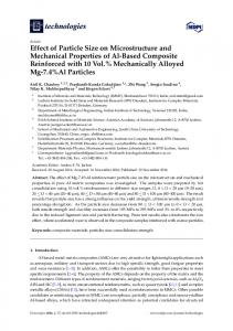
Microhardness profiles across the cross-section of the coatings are shown in Figure 10. It can be Microhardness profiles across the cross-section of the coatings are shown in Figure 10. It can clearly seen that the coating with 30 wt % NbC added in Stellite 6 has the highest microhardness 3.3. Microhardness be clearly seen that the coating with 30 wt % NbC added in Stellite 6 has the highest microhardness (598.2 HV0.5 for coating 3), which is attributed to the high-hardness reinforcement of NbC uniform Microhardness across the cross-section ofhigh-hardness the coatings are reinforcement shown in Figureof 10.NbC It also canuniform be (598.2 HV 3), which attributed to the 0.5 for coating distribution in theprofiles matrix [19].isBesides, the addition of NbC-induced fine microstructure is clearly seen that the coating with 30 wt % NbC added in Stellite 6 has the highest microhardness distribution in the matrix [19]. Besides, the addition of NbC-induced fine microstructure favorable for the further improvement in hardness/strength of the coating. However, for the coating is also (598.2 HV 0.5 coating 3), in which is 6, attributed the decrease high-hardness reinforcement of NbC with 15the wtfor % WS 2 added Stellite there is a to slight of the (431.2. HV 0.5the for coating favorable for further improvement in hardness/strength of themicrohardness coating. However, foruniform distribution in the matrix [19]. Besides, the addition of NbC-induced fine microstructure is of also coating 2) compared with Stellite 6 coating (454.2 HV 0.5 for coating 1). Moreover, fixed the content with 15 wt % WS2 added in Stellite 6, there is a slight decrease of the microhardness (431.2. HV0.5 favorable for30 the in hardness/strength of2 from the coating. coating NbC with wtfurther % and improvement increasing gradually the content of WS 10 wt %However, to 20 wt %,for thethe average for coating 2) compared with Stellite 6 coating (454.2 HV0.5 for coating 1). Moreover, fixed the microhardness the composite a decreasing as analyzed(431.2. above HV (587.3 with 15 wt % WS2of added in Stellitecoatings 6, there present is a slight decrease oftendency the microhardness 0.5 for content of 0.5 NbC with 30 wt %Stellite and increasing gradually thefor content of6).WS 10the wtmixture % to 20 wt %, 2 from HV forcompared coating 4, with 546.6 HV 0.5 for coating 5, and 534.6 coating According to coating 2) 6 coating (454.2 HV0.5HV for0.5coating 1). Moreover, fixed content of the average microhardness ofthe theaddition composite coatings present decreasing as the analyzed principle composites, of soft material in of hard decrease of a above NbC with 30ofwt % and increasing gradually the content WSamatrix 2 from can 10 wt %tendency to 20the wthardness %, average metal-matrix composite material [25]. CrS is relatively soft534.6 compared matrix. It was (587.3microhardness HV 546.6 HV coating and HV0.5with for coating 6). According to 0.5 for coating 0.5 for of the 4, composite coatings present a5,decreasing tendency as metal analyzed above (587.3 that the microhardness ofthe theaddition coating near the0.5material interface dramatically decreased; this the mixture of composites, of soft in6). hard matrix the HVnoticed 0.5 forprinciple coating 4, 546.6 HV0.5 for coating 5, and 534.6 HV for coating According tocan the decrease mixture phenomenon is similarthe to addition Ya’s report [26];material coarse structure and little NbChardness phase (as principle composites, ofmaterial soft hard is matrix canreinforced decrease the of ametal hardness of aofmetal-matrix composite [25].in CrS relatively soft compared with shown in Figure 10) are the main reasons that lead to hardness decrease. It was also found thatItthe metal-matrix composite material [25]. CrS is relatively soft compared with metal matrix. was matrix. It was noticed that the microhardness of the coating near the interface dramatically decreased; microhardness of all coatings increases sharply in the heat affected zone (HAZ), which should be noticed that the microhardness the coating near the interfaceand dramatically decreased; thisphase this phenomenon Ya’sofreport [26]; coarse structure little reinforced attributed to is thesimilar fact thattosubstrate was quenched during laser cladding process due to the NbC high phenomenon is similar to Ya’s report [26]; coarse structure and little reinforced NbC phase (as (as shown in Figure 10) are the main reasons that lead to hardness decrease. It was also found that cooling rate [23]. shown in Figure 10) are the main reasons that lead to hardness decrease. It was also found that the the microhardness of all coatings increases sharply in the heat affected zone (HAZ), which should microhardness of all coatings increases sharply in the heat affected zone (HAZ), which should be be attributed to the fact that substrate was quenched during laser cladding process due to the high attributed to the fact that substrate was quenched during laser cladding process due to the high cooling rate rate [23].[23]. cooling
Figure 10. Microhardness distribution across the cross-section of the coatings.
3.4. Tribological Behavior Figure 11 shows the changes in friction coefficient of the coatings against a WC ball under dry sliding condition temperature. In contrast, thecross-section frication coefficient of coating 1 and Figureat10.ambient Microhardness distribution across the of the coatings. 10.greatly Microhardness distribution across the cross-section the coatings. coating 3Figure fluctuate with the sliding time. The frication coefficient ofofcoating 2 and coating 4 vary a little with the sliding time. Moreover, their friction coefficient was stable during in dry sliding 3.4. Tribological Behavior
3.4. Tribological Behavior
Figure 11 shows the changes in friction coefficient of the coatings against a WC ball under dry
sliding 11 condition temperature. In contrast, of thethe frication coefficient coating and dry Figure shows at theambient changes in friction coefficient coatings against of a WC ball 1under coating 3 fluctuate greatly with the sliding time. The frication coefficient of coating 2 and coating 4 sliding condition at ambient temperature. In contrast, the frication coefficient of coating 1 and coating vary a little with the sliding time. Moreover, their friction coefficient was stable during in dry sliding 3 fluctuate greatly with the sliding time. The frication coefficient of coating 2 and coating 4 vary a little with the sliding time. Moreover, their friction coefficient was stable during in dry sliding wear testing. For coating 5 and coating 6, their friction coefficient presents an increasing trend with sliding time and
Materials 2018, 11, 44
Materials 2018, 11, 44
10 of 13
10 of 14
wear testing. For coating 5 and coating 6, their friction coefficient presents an increasing trend with
fluctuates greatly at the later period of sliding friction test. This may be caused by the wear device sliding time and fluctuates greatly at the later period of sliding friction test. This may be caused by (see Figure 3). Due to (see the limited the debris is not easy to the friction the wear device Figure of 3). friction Due to device, the limited of friction device, thedischarge debris is from not easy to zone;discharge part of the falling debriszone; crushed into friction area, resulting in friction increased fluctuation from the friction part of thethe falling debris crushed into the area, resulting inof the friction coefficient. increased fluctuation of the friction coefficient.
Figure 11. The changes in friction coefficient with the sliding time of coatings.
Figure 11. The changes in friction coefficient with the sliding time of coatings.
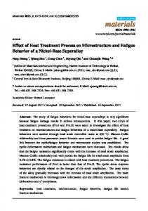
The average friction coefficient and wear rate of the coatings were also calculated (seeing Figure
The average friction coefficient and wear rate of the coatings were also calculated 12). The friction coefficient of coating 2 (0.434) and coating 3 (0.456) are lower than the coating 1 (seeing Figure 12). The friction coefficient of coating 2 (0.434) and coating 3 (0.456) are lower than (0.489); moreover, the wear rate of coating 2 (7.02 × 10⁻⁵ mm3/N·m) and coating 3 (7.86 × 10⁻⁵ 3 /N·m) and coating 3 the coating 1 (0.489); the wear rate of−4coating 2 (7.02 × 10⁻⁵ that mmboth mm3/N·m) are far moreover, less than coating 1 (2.43 × 10 mm3/N·m). It indicated CrS and NbC − 5 3 − 4 3 (7.86 contribute × 10 mm ·m) are the far less than coating 1 (2.43 mm /N It performance indicated that to /N improving tribological properties of × the10coatings. The·m). wear ofboth the CrS and NbC contribute to improving the tribological properties of the coatings. The wear performance coatings is closely related to the microstructural evolution resulting from the addition of WS2 and of NbC as isdiscussed in Section 3.2.microstructural The synthetic self-lubrication phasefrom CrS the is favorable the2 and the coatings closely related to the evolution resulting addition for of WS coating’s anti-wear andsynthetic friction reduction capabilities [14,19]. Moreover, of NbC composite as discussed in Section 3.2. The self-lubrication phase CrS is favorablethe foraddition the composite NbC anti-wear can not only to microstructural fineness, but also Moreover, result in a large number of of NbC ceramic coating’s andlead friction reduction capabilities [14,19]. the addition can not distribute in the fineness, coating, which endow thein coating excellent wear resistance [21,27]. only particles lead to microstructural but also result a largewith number of ceramic particles distribute However, there are no similar reports about the comprehensive impact of CrS and NbC on the wear in the coating, which endow the coating with excellent wear resistance [21,27]. However, there are no behavior of laser clad coatings. Although the coating 4, coating 5, and coating 6 also exhibited good similar reports about the comprehensive impact of CrS and NbC on the wear behavior of laser clad wear resistance as shown in Figure 12, the average friction coefficient of coating 4 (0.421), coating 5 coatings. Although the coating coating and coating alsothe exhibited resistance shown (0.451), and coating 6 (0.495)4,shows an5,upward trend 6with increasegood in thewear addition of WS2as . To in Figure 12, the average friction coefficient of coating 4 (0.421), coating 5 (0.451), and coating 6 (0.495) further characterize the CrS and NbC on the tribological behavior of these types of coatings, SEM shows an upwardoftrend withsurfaces the increase in the addition of WS further the CrS and micrographs the worn are provided in Figure 13. There were some characterize wear debris, patches, 2 . To serious plastic deformation worn surface of coating 1 (as shown in of Figure 13a); surfaces this NbC and on the tribological behavior of on these types of coatings, SEM micrographs the worn illustratedinthat the 13. coating suffered severewear adhesive wear. The worn coating 2 is very on are provided Figure There were some debris, patches, and surface seriousof plastic deformation for some spalling (as shown Figure 13b). According to the EDS result of wornsmooth surfaceexcept of coating 1 (as showncraters in Figure 13a); in this illustrated that the coating suffered severe position A (listed in Table 3), the worn surface of the coating 2 composed of Cr, Co, Fe, S adhesive wear. The worn surface of coating 2 is very smooth except for some spalling cratersand (as shown indicated CrS has been released and smeared on the wear surface due to its inherent soft and solid in Figure 13b). According to the EDS result of position A (listed in Table 3), the worn surface of the lubricant character, which can reduce the friction coefficients between the friction pair interface coating 2 composed of Cr, Co, Fe, and S indicated CrS has been released and smeared on the wear [14,28]. The worn surface of coating 3 is relatively smooth with only slight scratches characteristics surface to its softwhich and solid lubricant character, which can the This friction coefficients (as due shown in inherent Figure 13c), indicates that the slight abrasive wearreduce occurred. should be between the friction [14,28]. Themicrostructural worn surface of coating 3 isthat relatively with only attributed to the pair high interface hardness and refined of the coating make it smooth very difficult slighttoscratches characteristics shown in Figure thatThe the slight abrasive be plastically deformed (as or plowed during the13c), dry which sliding indicates wear [29,30]. worn surface of wear coating 4 isshould very smooth and has no spalling plastically deformation, or scratchesofonthe it (as occurred. This be attributed to the highcrater, hardness and refined microstructural coating shownitinvery Figure 13d). Ittoshows that coating 4 has good properties. However, worn that make difficult be plastically deformed or tribological plowed during the dry slidingthe wear [29,30]. surface of coating 5 and coating 6 are obviously different to coating 4; black traces of lubricious film or The worn surface of coating 4 is very smooth and has no spalling crater, plastically deformation, and larger spalling crater are visible on the worn surface (as shown in Figure 13e,f). According to the scratches on it (as shown in Figure 13d). It shows that coating 4 has good tribological properties. EDS result of position B, C, and D (listed in Table 3), the worn surface of coating 4, coating 5, and However, the worn surface of coating 5 and coating 6 are obviously different to coating 4; black traces coating 6 composed of Cr, Co, Nb, and S elements indicated that hard NbC and lubricant CrS have of lubricious film and larger spalling crater are visible on the worn surface (as shown in Figure 13e,f). been released on the worn surface. Though the content of CrS is higher than the increase in the According to the EDS result of position B, C, and D (listed in Table 3), the worn surface of coating 4, coating 5, and coating 6 composed of Cr, Co, Nb, and S elements indicated that hard NbC and lubricant CrS have been released on the worn surface. Though the content of CrS is higher than the increase in the addition of WS2 , but more CrS and larger NbC were crushed into the friction area, resulting in
Materials 2018,2018, 11, 44 Materials 11, 44
11 of 13 11 of 14
addition of WS2, but more CrS and larger NbC were crushed into the friction area, resulting in a lot Materials 2018,craters 11, 44 on 11 14 a lot of spalling craters onthe thewear wearsurface. surface. Worse still, these spalling craters harmful to offorming of spalling Worse still, these spalling craters werewere harmful to forming continuous transfer film, resulting in an increase and a fluctuation of the friction coefficient [15,31]. continuous transfer film, resulting in an increase and a fluctuation of the friction coefficient [15,31]. addition of WS2, butperformance more CrS and larger NbC wereproperty crushed into the friction in aand lot In fact, tribological comprehensive ininrelation to both theresulting lubrication In fact, tribological performance isisa acomprehensive property relation to area, both the lubrication and of spalling craters on parameters the wear surface. WorseAdditionally, still, these spalling cratersbalance were harmful to forming the other mechanical materials. of CrS and NbC NbC is the other mechanical parameters ofofmaterials. Additionally,the thesuitable suitable balance of CrS and is continuous film,friction resulting inimproving an increase and a fluctuation of surfaces the friction coefficient [15,31]. favorable totransfer decreasing andimproving stability of the contact between the WC ball favorable to decreasing friction and stability of the contact surfaces between the WC ball In fact, a comprehensive in relation to both the lubrication and and the tribological coatings. Inperformance research,iscoating shows theproperty properties. and the In thisthis research, 44shows the best besttribological tribological the coatings. other mechanical parameterscoating of materials. Additionally, the suitable properties. balance of CrS and NbC is
favorable to decreasing friction and improving stability of the contact surfaces between the WC ball and the coatings. In this research, coating 4 shows the best tribological properties.
(a)
(b)
Figure 12. Friction coefficient (a) and wear rates (b) of coatings. Figure 12. Friction coefficient (a) and wear rates (b) of coatings.
Figure 12. Friction coefficient (a) and wear rates (b) of coatings.
Figure 13. SEM micrographs of the worn surfaces of coatings: (a) coating 1, (b) coating 2, (c) coating Figure 13. SEM micrographs of the worn surfaces of coatings: (a) coating 1, (b) coating 2, (c) coating 3, 3, (d) coating 4, (e) coating 5, and (f) coating 6. (d) coating 4, (e) coating 5, and (f) coating 6. Table 3. EDS-determined compositions of the regions on the worn surfaces marked in Figure 13.
Table 3. EDS-determined compositions of the regions on the worn surfaces marked in Figure 13. Element (at. %) Point No. S Cr Nb W Co Element C (at. %) Fe Point No. A 1.40 22.76 2.93 S 9.37 Cr27.01 Nb C Fe W 36.53 Co 16.40 -19.77 1.40 5.95 15.74 3.22 A B 9.377.39 27.01 22.76 2.93 31.73 36.53 B C 7.3910.0516.40 15.74 3.22 28.82 31.73 21.73 19.77 15.93 5.95 3.09 17.32 3.04 C 10.05 21.73 15.93 3.09 17.32 3.04 28.82 13.6825.59 25.59 9.239.23 2.57 2.57 18.74 3.39 D D 13.68 18.74 3.39 26.53 26.53
4. Conclusions
4. Conclusions (1)
Co-based metal matrix self-lubricating coatings containing solid-lubricant phase CrS and ceramic reinforced phase NbC were successfully fabricated on Cr12MoV steel surface by laser cladding Stellite 6, WS2 , and NbC matrix powder.
Materials 2018, 11, 44
(2)
(3)
(4)
12 of 13
Reactions between WS2 and Stellite 6 occurred, which generated solid-lubricant particles CrS and NbC that play a key role in improving the CrS nuclear and refining microstructure of the Co-based composite coating during laser cladding processing. The average microhardnesses of coating 4, coating 5, and coating 6 are 587.3 HV0.5 , 546.6 HV0.5 , and 534.6 HV0.5 , respectively. NbC reinforcements and fine microstructure contribute a higher level of microhardness. The formation of soft CrS and the coarse NbC particles result in a slight decrease in microhardness. Both CrS and NbC contribute to improving the tribological properties of the coating, and the suitable balance of CrS and NbC favorable to decreasing the friction and improving the stability of the contact surfaces between the frictional pair and the coatings. In this research, coating 4 shows the best tribological properties.
Acknowledgments: This work was supported by the National Natural Science Foundation of China (51405288, 51605276) and Shanghai Science and Technology Committee Innovation Grant (17JC1400600, 17JC1400601). Author Contributions: Liuyang Fang and Hua Yan conceived and designed the experiments; Liuyang Fang, Yansong Yao, Qiushi Gao, and Yang Qin performed the experiments; Hua Yan and Peilei Zhang congtributed materials and tools; Hua Yan and Peilei Zhang also provided advice in all issues; Liuyang Fang wrote the paper; all of the authors were involved in writing the final paper. Conflicts of Interest: The authors declare no conflict of interest.
References 1. 2. 3.
4. 5.
6.
7. 8. 9.
10.
11. 12.
Voevodin, A.A.; Muratore, C.; Aouadi, S.M. Hard coatings with high temperature adaptive lubrication and contact thermal management: Review. Surf. Coat. Technol. 2014, 257, 247–265. [CrossRef] Zhang, A.; Han, J.; Su, B.; Li, P.; Meng, J. Microstructure, mechanical properties and tribological performance of CoCrFeNi high entropy alloy matrix self-lubricating composite. Mater. Des. 2017, 114, 253–263. [CrossRef] Su, Y.; Zhang, Y.; Song, J.; Hu, L. Tribological behavior and lubrication mechanism of self-lubricating ceramic/metal composites: The effect of matrix type on the friction and wear properties. Wear 2017, 372–373, 130–138. [CrossRef] Duan, W.; Sun, Y.; Liu, C.; Liu, S.; Li, Y.; Ding, C.; Yu, L. Study on the formation mechanism of the glaze film formed on Ni/Ag composites. Tribol. Int. 2016, 95, 324–332. [CrossRef] Villavicencio, M.D.; Renouf, M.; Saulot, A.; Michel, Y.; Mahéo, Y.; Colas, G.; Filleter, T.; Berthier, Y. Self-lubricating composite bearings: Effect of fibre length on its tribological properties by DEM modeling. Tribol. Int. 2017, 113, 362–369. [CrossRef] Yan, H.; Zhang, P.; Yu, Z.; Lu, Q.; Yang, S.; Li, C. Microstructure and tribological properties of laser-clad Ni-Cr/TiB2 composite coatings on copper with the addition of CaF2 . Microstructure and tribological properties of laser-clad Ni-Cr/TiB2 composite coatings on copper with the addition of CaF2 . Surf. Coat. Technol. 2012, 206, 4046–4053. [CrossRef] Zhang, A.; Han, J.; Su, B.; Meng, J. A novel CoCrFeNi high entropy alloy matrix self-lubricating composite. J. Alloys Compd. 2017, 725, 700–710. [CrossRef] Lei, Y.; Sun, R.; Tang, Y.; Niu, W. Microstructure and phase transformations in laser clad Crx Sy /Ni coating on H13 steel. Opt. Laser Eng. 2015, 66, 181–186. [CrossRef] Tekmen, C.; Ozdemir, I.; Fritsche, G.; Tsunekawa, Y. Structural evolution of mechanically alloyed Al-12Si/TiB2 /h-BN composite powder coating by atmospheric plasma spraying. Surf. Coat. Technol. 2009, 203, 2046–2051. [CrossRef] Liu, Y.; Mu, J.; Xu, X.; Yang, S. Microstructure and dry-sliding wear properties of TiC reinforced composite coating prepared by plasma-transferred arc weld surfacing process. Mater. Sci. Eng. A 2007, 458, 366–370. [CrossRef] He, Y.; Sun, W.; Wang, S.; Reed, P.A.S.; Walsh, F. An electrodeposited Ni-P-WS2 coating with combined super-hydrophobicity and self-lubricating properties. Electrochim. Acta 2017, 245, 872–882. [CrossRef] Leon, O.A.; Staia, M.H.; Hintermann, H. Wear mechanism of Ni–P–BN(h) composite autocatalytic coatings. Surf. Coat. Technol. 2005, 200, 1825–1829. [CrossRef]
Materials 2018, 11, 44
13. 14.
15. 16. 17.
18.
19.
20.
21. 22. 23. 24. 25.
26. 27.
28.
29.
30.
31.
13 of 13
Nolan, D.; Huang, S.W.; Leskovsek, V.; Braun, S. Sliding wear of titanium nitride thin films deposited on Ti-6Al-4V alloy by PVD and plasma nitriding processes. Surf. Coat. Technol. 2006, 200, 698–705. [CrossRef] Yang, M.; Liu, X.; Fan, J.; He, X.; Shi, S.; Fu, G.; Wang, M.; Chen, S. Microstructure and wear behaviors of laser clad NiCr/Cr3 C2 -WS2 high temperatnologyure self-lubricating wear-resistant composite coating. Appl. Surf. Sci. 2012, 258, 3757–3762. [CrossRef] Weng, F.; Yu, H.; Chen, C.; Dai, J. Microstructures and wear properties of laser cladding Co-based composite coatings on Ti-6Al-4V. Mater. Des. 2015, 80, 174–181. [CrossRef] Wang, A.; Zhang, X.; Zhang, X.; Qiao, X.; Xu, H.; Xie, C. Ni-based alloy/submicron WS2 self-lubricating composite coating synthesized by Nd:YAG laser cladding. Mater. Sci. Eng. A 2008, 475, 312–318. [CrossRef] Liu, X.; Zheng, C.; Liu, Y.; Fan, J.; Yang, M.; He, X.; Wang, M.; Yang, H.; Qi, L. A comparative study of laser cladding high temperature wear-resistant composite coating with the addition of self-lubricating WS2 and WS2 (Ni–P) encapsulation. J. Mater. Process. Technol. 2013, 213, 51–58. [CrossRef] Skarvelis, P.; Rokanopoulou, A.; Papadimitriou, G.D. Formation of TiS and Ti4 C2 S2 in steel matrix composite sprepared by the plasma transferred arc (PTA) technique using TiS2 and TiC powders. Tribol. Int. 2013, 66, 44–48. [CrossRef] Lu, X.; Liu, X.; Yu, P.; Fu, G.; Zhu, G.; Wang, Y.; Chen, Y. Effects of annealing on laser clad Ti2 SC/CrS self-lubricating anti-wear composite coating on Ti6Al4V alloy: Microstructure and tribology. Tribol. Int. 2016, 101, 356–363. [CrossRef] Skarvelis, P.; Papadimitriou, G.D. Plasma transferred arc composite coatings with self-lubricating properties, based on Fe and Ti sulfides: Microstructure and tribological behavior. Surf. Coat. Technol. 2009, 203, 1384–1394. [CrossRef] Wei, B.; Wang, Y.; Zhao, Y.; Wang, D.; Song, G.; Fu, Y.; Zhou, Y. Effect of NbC content on microstructure and mechanical properties of W-NbC composites. Int. J. Refract. Met. Hard Mater. 2017, 70, 66–67. [CrossRef] Lv, Y.; Li, J.; Tao, Y.; Hu, L. High-temperature wear and oxidation behaviors of TiNi/Ti2 Ni matrix composite coatings with TaC addition prepared on Ti6Al4V by laser cladding. Appl. Surf. Sci. 2017, 402, 478–494. [CrossRef] Li, Q.; Lei, Y.; Fu, H. Laser cladding in-situ NbC particle reinforced Fe-based composite coatings with rare earth oxide addition. Surf. Coat. Technol. 2014, 239, 102–107. [CrossRef] AlMangour, B.; Grzesiak, D.; Yang, J.-M. In-situ formation of novel TiC-particle-reinforced 316L stainless steel bulk-form composites by selective laser melting. J. Alloys Compd. 2017, 706, 409–418. [CrossRef] Yan, H.; Zhang, J.; Zhang, P.; Yu, Z.; Li, C.; Xv, P.; Lu, Y. Laser cladding of Co-based alloy/TiC/CaF2 self-lubricating composite coatings on copper for continuous casting mold. Surf. Coat. Technol. 2013, 232, 362–369. [CrossRef] Ya, W.; Pathiraj, B.; Liu, S. 2D modeling of cladgeometry and resulting thermal cycles during laser cladding. J. Mater. Process. Technol. 2016, 230, 217–232. [CrossRef] AlMangour, B.; Grzesiak, D.; Yang, J.M. Rapid fabrication of bulk-form TiB2 /316L stainless steel nanocomposites with novel reinforcement architecture and improved performance by selective laser melting. J. Alloys Compd. 2016, 680, 480–493. [CrossRef] Liu, X.; Meng, X.; Liu, H.; Shi, G.; Wu, S.; Sun, C.; Wang, M.; Qi, L. Development and characterization of laser clad high temperature self-lubricating wear resistant composite coatings on Ti-6Al-4V alloy. Mater. Des. 2014, 55, 404–409. [CrossRef] Liu, X.; Meng, X.; Liu, H.; Shi, G.; Wu, S.; Sun, C.; Wang, M.; Qi, L. Investigation of laser cladding high temperature anti-wear composite coatings on Ti6Al4V alloy with the addition of self-lubricant CaF2 . Appl. Surf. Sci. 2014, 313, 243–250. [CrossRef] AlMangour, B.; Grzesiak, D.; Yang, J.M. Selective laser melting of TiC reinforced 316L stainless steel matrix nanocomposites: Influence of starting TiC particle size and volume content. Mater. Des. 2016, 104, 141–151. [CrossRef] Ozsarac, U.; Findik, F.; Durman, M. The wear behaviour investigation of sliding bearings with a designed testing machine. Mater. Des. 2007, 28, 345–350. [CrossRef] © 2017 by the authors. Licensee MDPI, Basel, Switzerland. This article is an open access article distributed under the terms and conditions of the Creative Commons Attribution (CC BY) license (http://creativecommons.org/licenses/by/4.0/).