Global Journal of Pure and Applied Mathematics. ISSN 0973-1768 Volume 11, Number 3 (2015), pp. 1157-1170 © Research India Publications http://www.ripublication.com
The Field Oriented Control of an Induction Motor Using FPGA Athul K S and Dr.N Ramesh Babu School Of Electrical Engineering, VIT University, Vellore, India
[email protected] [email protected]
Abstract This paper has realized the field oriented control (FOC) of an induction motor using Xilinx system generator toolbox to investigate the feasibility of embedding FOC into Field Programmable Gate Array (FPGA). The FOC of an induction motor is simulated in MATLAB Simulink environment with system generator blocksets. The aim is to get the desired speed at output. The controller design is tested with different controllers like PI, Fuzzy and hybrid PI-Fuzzy and compared their results. Keywords— FOC; FPGA; Fuzzy; induction motor
INTRODUCTION The main objective of this paper is to develop FOC algorithm for an induction motor using Xilinx System Generator toolbox added to Matlab Simulink[1]. For understanding better we have to first realize the FOC algorithm in Matlab environment without using Xilinx system generator. In recent years, we have seen a dramatic expansion in the field of control of an induction motor due to the achievements in semiconductors for both power and signal electronics. There are mainly two methods of induction motor control: scalar control and vector control. Scalar control of ac drives produces good steady state performance but poor dynamic response. This manifests itself in the deviation of air gap flux linkages from their set values. This variation occurs in both magnitude and phase. In scalar control there is an inherent coupling effect because both torque and flux are functions of voltage or current and frequency. This results in sluggish response. While Vector control (or field oriented control) offers more precise control of ac motors compared to scalar control. They are therefore used in high performance drives where oscillations in air gap flux linkages are intolerable, e.g. robotic actuators, centrifuges, servos, etc. Now a days FPGA’s is
I.
1158
Athul K S and Dr.N Ramesh Babu
gaining more popularity for implementing high performing processors[1],[4]. As FPGA’s is having more number of inputs and outputs compared to any other microcontroller and DSP, it is more appropriate for highly parallel arithmetic architecture. These technological improvements have allowed the development of very effective AC drive controls marked with lower power dissipation hardware and increasingly accurate control structures.
FIELD ORIENTED CONTROL In DC machines the torque and flux are in decoupled manner, so that we can control the speed of DC motor very easily. That is the armature current and field current are orthogonal to each other. But for the control of an AC induction motor the case is different, as the torque component current and the flux component current are in coupled manner. To obtain DC motor like property we have to maintain a fixed orthogonal orientation between the field and armature fields in the AC machine. Field orientated controlled machines need two constants as input references: the torque component (aligned with the q co-ordinate) and the flux component (aligned with d coordinate)[2],[3]. It can be achieved by orienting the stator current with respect to the rotor flux in a manner such that independent control of flux and torque is established. Field Oriented Control works on this principle. Even if this method requires more calculation than other methods it is having many advantages: full motor torque capability at low speed better dynamic behavior higher efficiency for each operation point in a wide speed range decoupled control of torque and flux short term overload capability four quadrant operation
II.
FOC is the controlling motor stator currents represented by vectors in rotating reference frame. Thus AC motor can be controlled like DC motor. FOC are mainly of two types. DFOC (Direct Field Oriented Control) - In this strategy rotor flux vector is either measured by means of a flux sensor mounted in the air-gap or by using the voltage equations starting from the electrical machine parameters. IFOC (Indirect Field Oriented Control)- In this strategy rotor flux vector is estimated using the field oriented control equations (current model) requiring a rotor speed measurement. The Field Orientated Control (FOC) consists of controlling the stator currents represented by a vector Measure the stator phase currents , and . If only the values of and are measured can be calculated as for balanced current + + = 0 Transform the set of these three-phase currents onto a two-axis system. This conversion provides the variables and from the measured , and values. This conversion is popularly known as Clarke Transformation.
The Field Oriented Control of an Induction Motor Using FPGA = 3/2
1159 (1)
= √3/2
- √3/2
(2)
Rotate the two-axis coordinate system such that it is in alignment with the rotor flux, using the transformation angle calculated at the last iteration of the control loop. This conversion provides the and variables from and . This step is more commonly known as the Park Transformation. =
cosθ +
sinθ
(3)
=-
sinθ +
cosθ
(4)
Flux error signal is formed using flux reference and estimated flux value. A PI controller is then used to calculate using this error signal. is generated using the reference torque value and the estimated flux value. and are converted to a set of three phase currents to produce , , . , , and , , are compared using hysteresis comparator to generate inverter gate signals.
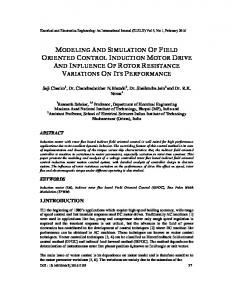
SIMULATION MODEL The FOC controller mainly consists of a PI controller which gives the torque component current and DQ to ABC conversion block which produces the stator current necessary for the control of an Induction motor. is the flux controlling current component. The three stator currents are given to the hysteresis comparator block and thus produces the gate signal for the inverter block. The output from the inverter is given to the Induction motor input to control the motor.
III.
Table 1: Induction motor specification Voltage 415 v Power 1.2 Kw Stator resistance (Rs) 4.1 ohm Stator inductance (Ls) 0.545 H Rotor resistance (Rr) 2.5 ohm Rotor inductance (Lr) 0.542 H Poles 4 Inertia constant (J) 0.04 kg m2
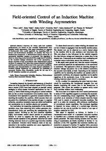
The FOC controller should be modelled using Xilinx system generator toolbox which gets integrated with Matlab Simulink when we install Xilinx ISE suite [5], [10]. We have to use the system generator blocks for designing the FOC mainly PI controller and DQ-ABC block. This block compares the estimated rotor flux and the
1160
Athul K S and Dr.N Ramesh Babu
reference rotor flux as the input to a Proportional Integrator which calculates the flux to be applied to the motor which in turn is used to compute the stator current direct component required to produce the required rotor flux in the machine. The Kp value is taken as 35 and Ki as 5. The theta angle needed for the DQ-ABC block is calculated indirectly using theta calculation and flux estimator block. Matlab Simulink software package provides a powerful high level modeling environment for people who are involved in system modeling and simulations. Xilinx System Generator Tool developed for Matlab Simulink package is widely used for algorithm development and verification purposes in Digital Signal Processors (DSP) and Field Programmable Gate Arrays (FPGAs) [5], [6]. System Generator Tool allows an abstraction level algorithm development while keeping the traditional Simulink blocksets, but at the same time automatically translating designs into hardware implementations that are faithful, synthesizable, and efficient. In a typical design flow supported by System Generator, the following steps are followed: 1. Describe the algorithm in mathematical terms; 2. Realize the algorithm in the design environment, initially using double precision; 3. Trim double precision arithmetic down to fixed point; 4. Translate the design into efficient hardware Here all the blocks are from system generator toolbox. That is the controller part is redesigned with system generator toolbox. The advantage of using system generator toolbox is that using this we can directly convert this controller part to VHDL or Verilog code which is used in FPGA. Thus there is no need to write a programme for simulation purpose and another programme code for the target device. Using this HIL(Hardware In Loop) simulation or co-simulation is also possible[5],[9]. As next step we use a fuzzy controller instead of PI controller in the FOC algorithm [7]. The fuzzy logic controller is developed based on mamdani method. The Fuzzy controller requires a set of rules which can be developed by an expert who knows the system well enough. Fuzzy control is a technique to emulate human deductive thinking to the controller. Fuzzy control consists of fuzzy linguistic descriptions. For fuzzy controller there are two inputs, speed error and differential of speed error. According to the rules, we get the output of the fuzzy controller. The input variables have 3 membership functions and output variable have 5 membership function. The fuzzy rules are expressed in IF-THEN form. The output of fuzzy logic controller is obtained using MAX-MIN inference algorithm and the center of gravity de-fuzzification approach.
The Field Oriented Control of an Induction Motor Using FPGA
1161
Table 2: Fuzzy rules e an de N Z P
N NB NM Z
Z NM Z PM
P Z PM PB
As a third step we use a hybrid PI and fuzzy approach in FOC algorithm [8]. The fuzzy and the PI are added together in the FOC algorithm. The same specification discussed above is used for PI and Fuzzy design. Table 3: Comparison between the controllers Controller Rise time (Tr) sec Settling time (Ts) sec PI 0.153 0.17 Fuzzy 0.54 0.6 PI-Fuzzy 0.09 0.1
HARDWARE CO-SIMULATION The FOC controller using PI developed is imbedded on Xilinx Virtex 5 xc5vlx110t11ff1136 Field Programmable Gate Array (FPGA) using Xilinx System generator toolbox and the simulation with FPGA is done in Matlab Simulink environment. The controlling action fully takes place inside the FPGA kit. It takes the input from the Simulink part, processes inside the FPGA for controlling, and the output is given to the induction motor in the Simulink. The JTAG-USB connector is used for interfacing the FPGA kit to the Matlab Simulink. The output using FPGA as controller is given.
IV.
Table 4: Resource report for the design Number of slices 1610 out of 17,280 Number of flipflops 5,225 out of 69,120 Number of slice LUTs 5,514 out of 69,120 Number of bonded IOBs 376 out of 640
9% 7% 7% 58%
CONCLUSION In this paper we have succeeded in implementing the FOC algorithm using Xilinx system generator tool (XSG) which is very useful in terms of simulation purpose and embedding the code into the target FPGA. The inbuilt autocode generation feature in system generator will enable to build a code in VHDL or Verilog which is suitable for the FPGA. Thus the controller designed using this approach gives the required result in Matlab Simulink. Another important advantage of using Xilinx System Generator design structure is that it provides resource estimation to the user so that the user can
V.
1162
Athul K S and Dr.N Ramesh Babu
determine an appropriate FPGA for his design. On the other hand, the induction machine controller design completed with the method used in this study allows the designer to observe easily the effects of hysteresis band, different PI controller coefficients in the regulator. By comparing the FOC algorithm with different controllers like PI, Fuzzy, hybrid PI-Fuzzy we found the differences between them. Thus result shows the hybrid PI- Fuzzy controller is giving less rise time and settling time compared to other two. Thus we can say that performance of hybrid PI-Fuzzy is more compared to other two. The designed controller is then embedded into FPGA and the analysis is done. Using the resource estimator, the resource report for the design is generated. By this method thus an optimized controller can be designed by foreseeing the errors that occurred while developing the experimental prototype.
ia ib ic
r
iqs*
i
ids*
* ds
* ia* ib* ic
iqs*
e
ids iqs
*
Figure 3: Stator current space vectors
Figure 1: Basic block diagram of FOC
The Field Oriented Control of an Induction Motor Using FPGA
Figure 3: Clarke Transformation
Figure 4: Park Transformation
Figure 6: FOC of an Induction motor using xilinx system generator
1163
1164
Athul K S and Dr.N Ramesh Babu
Figure 7: Virtex sub block with PI controller 8
6
Current (A)
4
2
0
-2
-4
-6 0
0.2
0.4
0.6
0.8 1 1.2 Time (seconds)
1.4
1.6
1.8
2
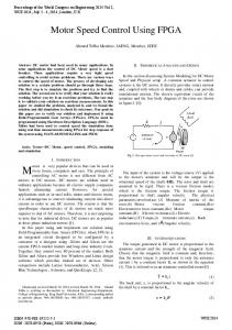
Figure 8: Current waveform 1400
1200
speed (rpm)
1000
800
600
400
200
0
0
0.2
0.4
0.6
0.8 1 1.2 Time (seconds)
1.4
1.6
Figure 9: Torque waveform
1.8
2
The Field Oriented Control of an Induction Motor Using FPGA
1165
14 12 10
Torque (N-m)
8 6 4 2 0 -2 -4 -6
0
0.2
0.4
0.6
0.8 1 1.2 Time (seconds)
1.4
1.6
1.8
2
Figure 10: Speed waveform
Figure 11: Membership function of first input variable
Figure 15: Virtex sub block with Fuzzy Controller
1166
Athul K S and Dr.N Ramesh Babu
Figure 13: Membership function of output variable
Figure 12: Membership function of second input variable 1400 1200 1000
speed (rpm)
800 600 400 200 0 -200
0
0.2
0.4
0.6
0.8 1 1.2 Time (seconds)
1.4
1.6
Figure 18: Speed waveform
1.8
2
The Field Oriented Control of an Induction Motor Using FPGA
1167
6
4
Torque (N-m)
2
0
-2
-4
-6
-8 0
0.2
0.4
0.6
0.8 1 1.2 Time (seconds)
1.4
1.6
1.8
2
Figure 12: Membership function of second input variable
Figure 19: Virtex sub block with Hybrid PI-Fuzzy Controller 20 15 10
Current (A)
5 0 -5 -10 -15 -20
0
0.2
0.4
0.6
0.8 1 1.2 Time (seconds)
1.4
1.6
Figure 20: Current waveform
1.8
2
1168
Athul K S and Dr.N Ramesh Babu 40 35 30
Torque (N-m)
25 20 15 10 5 0 -5 -10
0
0.2
0.4
0.6
0.8 1 1.2 Time (seconds)
1.4
1.6
1.8
2
Figure 21: Torque waveform
Figure22: Speed waveform
Figure24: Hardware Co-Simulation using JTAG
The Field Oriented Control of an Induction Motor Using FPGA
1169
Figure 23: Virtex 5 xc5vlx110t
Figure 26: Torque waveform 1400
1200
speed (rpm)
1000
800
600
400
200
0
0
0.2
0.4
0.6
0.8 1 1.2 Time (seconds)
1.4
1.6
Figure 27: Speed waveform
1.8
2
1170
Athul K S and Dr.N Ramesh Babu 14 12 10
Torque (N-m)
8 6 4 2 0 -2 -4 -6
0
0.2
0.4
0.6
0.8 1 1.2 Time (seconds)
1.4
1.6
1.8
2
Figure 25: Current waveform REFERENCES [1] [2]
[3] [4]
[5] [6]
[7]
[8] [9]
[10]
O. Akın, “The Use of FPGA in Field Oriented Control of an Induction Machine”, Turk J Elec Eng & Comp Sci, Vol.18, No.6, 2010 Xiang Zhao, Huijuan Liu, Jingxiong Zhang, Haijiao Zhang, “Simulation of Field Oriented Control in Induction Motor Drive System”, TELKOMNIKA, Vol. 11, No. 12, December 2013 BPRA073, “Field Orientated Control of 3-Phase AC-Motors Literature, Texas Instruments Europe Inc.,www.ti.com, 1998 J. Vasarhelyi, M. Imecs, C. Szabo, I. I. Incze, T. Adam, “FPGA Implementation of the Reconfigurable Control System for AC Drives Fed by Tandem Converter”, 2005. Xilinx Corp., “Xilinx System Generator v2.1 Reference Guide for Simulink, www.xilinx.com F. Ricci, H. L. Luy, “Modeling and Simulation of FPGA Based VariableSpeed Drives Using Simulink”, Mathematics and Computers in Simulation, Volume 63, Issue 3-5, pp. 183-195, ISSN: 0378-4754, 2003. A.Mechernene, M.Zerikat & M.Hachblef, “Fuzzy Speed Regulation for Induction Motor Associated With Field-Oriented Control”, IJSTA, Vol. 2, pp 804-817. I. Miki, Et Al.(1991) “Vector Control Of Induction Motor With Fuzzy PI Controller,” IEEE Conference, IAS Annu. Meeting, Vol. 1, pp341-346. S. K. Sahoo, G. T. R. Das, V. Subrahmanyam, “Implementation and Simulation of Direct Torque Control Scheme with the Use of FPGA Circuit”, ARPN Journal of Engineering and Applied Sciences, Vol. 3, No. 2, ISSN: 1819-6608, 2008. F. Ricci, H. L. Luy, “Modeling and Simulation of FPGA Based VariableSpeed Drives Using Simulink”, Mathematics and Computers in Simulation, Volume 63, Issue 3-5, pp. 183-195, ISSN: 0378-4754, 2003.