Sliding Mode Control of a Field Oriented Induction Motor Using Xilinx System Generator Sghaier Narjess, Trabelsi Ramzi, Sofiene Gdaim
Badre Bossoufi, Mohamed Fouzi Mimouni
The National Engineering School of Monastir Ibn El jazzar City, 5019, Monastir, Tunisia
[email protected] - phone: 0021697537202
The National Engineering School of Monastir Ibn El jazzar City, 5019, Monastir, Tunisia STIC-Team, FSDM-Fez, Morocco
Abstract— The objective of this paper is to get the VHDL code of the Sliding mode control of a field oriented induction motor without requiring to go through a programming language. The solution that we proposed in this paper is to use the Xilinx System Generator (XSG) blockset added to Matlab / Simulink. The interest of this proposed method is to profit of both advantages of simulink and XSG. The first simulates the control and test its proper functioning and the second allows to obtain the discrete algorithm and to have the VHDL code that can be implemented on FPGA. Keywords- FPGA, Induction Motor, Sliding Mode Control, Rotor Flux Oriented, Xilinx System Generator, Matlab & Simulink.
of non-linear control leading the state trajectory toward the sliding surface in a finite time This type of control applied to the induction machine has been treated by several authors and the majority of authors have presented Simulink simulations but the contribution of this paper is to present a new Simulink block set added: Xilinx System Generator (XSG). The interest of this toolbox it enables to automatically generate the VHDL code that will be implemented on the FPGA board without using any programming language. The XSG advantage that it allows us to visualize the behavior of our system and get the sampled algorithm that will be directly implemented on the FPGA board just by pressing the button Generate. II.
I.
THE EQUATIONS OF THE INDUCTION MOTOR WITH THE ROTOR FLUX ORIENTED
INTRODUCTION
Currently, the control of electric machines are typically implemented on two types of programmable platform or DSPs and FPGAs (field programmable gate arrays). The FPGAs can perform multiple operations in parallel, which gives them an advantage over DSPs. The advantage of this interdisciplinary engineering field is to develop powerful automated systems and to allow the control of complex hybrid systems. The DSP platforms which including a board as the dSPACE DS1104 are excellent tools still used today for rapid prototyping of control. As these boards use the floating point DSPs with a high-level software language, it is a less appropriate tools to support the control of highly modular applications. With the langages to description of hardware such as VHDL and synthesis tools for FPGAs inexpensive, A rapid prototyping of modular and complex algorithms is an effective solution already observable. The sliding mode control is a control categorized in variable structure controls. This is a nonlinear control based on switching on the level of the control. It forces the system dynamics to achieve specified surface and selected in the state space, called sliding surface, and to maintain the trajectories of the system on this surface. Although this control technique has indisputable advantages and especially robustness opposite the disturbances and parametric variations, it has some disadvantages, especially the heavy use of controls elements. To develop a sliding mode control, we proceed normally in two stages. The first consists in the synthesis of a sliding surface representing the desired dynamics of the system by sliding mode. The second stage concerns the determination of the law
Starting from the equations for the functioning of the induction motor presented in a reference rotating frame (d-q) and by considering the flux orientation ϕr on the d-axis: •
ϕ rq and ϕ rq = 0 , we obtain these equations : μ
C ϕd i sq − r J J ϕd = −α.ϕd + α.M.i sd ω=
i sd = −η.i sd + αβϕd + Pω.i sq + α.M.
2 i sq
1
+
u ϕd σLs d i sd .i sq 1 uq i sq = −η.i sq + Pαβϕd + Pω.i sq + α.M. + ϕd σLs i sq θs = P.ω + α.M ϕd (1) With: α=
Rr
; μ=
PM
; β=
Lr Lr 2 2 M R r + LrRs η= 2 σL s L r
M σL s L r
;
Nomenclature: Vsd ,Vsq: Direct and quadrature axis stator voltage. isd ,isq: Direct and quadrature axis stator currents. d, q: d- and q-axis rotating reference frame. α,β:α- and β-axis stationary reference frame ω: Rotation's speed electric. ws: Electrical synchronous speed. p: Number of pairs of poles. J : Total moment of inertia. f : Coefficient of viscous friction. Cr: Resistive torque. M: Mutual inductance. σ: Leakage coefficient. φrd: d axis stator magnetic flux. φrq: q axis stator magnetic flux. Ls: Stator leakage inductance. Lr: Rotor leakage inductance. Rs: Stator resistance. Tr: rotor time constant Cem: Eectromagnetic torque. III.
i sdref = i sdeq + i sdn
(10)
B. The speed controller •
•
•
S( w ) = w ref − w = 0 • C μ w ref − ϕ d .i sq + r = 0 J J C μ i sqeq = ϕ d .i sq − r = 0 J J
(11) (12) (13)
The control that allows to ensure attractiveness is:
i sqn
⎧K w .S( w ) si S( w ) ≺ ε w ⎪ = ⎨ εw ⎪K w .sign (S( w )) si S( w ) ⎩ i sqref = i sqeq + i sqn
(14)
εw (15)
C. The direct component of the stator current controller According to the derivative of the surface of the current isd, we can express the voltage of control on d-axis
SYNTHESIS OF THE LAW OF THE SLIDING MODE CONTROL
We take the following surfaces: •
S( w ) = w ref − w
•
•
S(i sd ) = i sdref − i sd = 0
(2) •
S(ϕ d ) = ϕ ref − ϕ d
(3)
S(i sd ) = i sdref − i sd
(4)
S(i sq ) = i sqref − i sq
(5)
i sdref + η i sd − w s .i sq − αβ.ϕ d −
(16)
1 u sd = 0 σL s
(17)
Therefore,
⎡• ⎤ u sdeq = σL s ⎢i sd + η i sd − w s .i sq − αβ.ϕ d ⎥ ⎣ ⎦
(18)
The control that allows to ensure attractiveness is: A. The flux controller A necessary condition in order that the system status follow
u sdeq
•
the trajectory defined by the sliding surfaces is: S = 0 . This brings us to define the equivalent control of the module of the rotor flux as follows: •
•
•
S(ϕ d ) = ϕ ref − ϕ d •
(19)
εd
D. The quadratic component of the stator current
(7)
According to the derivative of the surface of the current isq, we can express the voltage of control on q-axis •
•
•
S(i sq ) = i sqref − i sq = 0
We get to write:
•
i sdeq = −αϕ d + αMi sd
(8)
The following proposition given in [11] allows to ensure the attractiveness;
⎧Kf ⎪ .S(ϕ d ) si S(ϕ d ) ≺ ε f = ⎨ εf ⎪⎩K f .sign (S(ϕ d )) si S(ϕ d )
(20)
(6)
•
S(ϕ d ) = ϕ ref + αϕ d − αM.i sd
i sdn
⎧Kd .S(i sd ) si S(i sd ) ≺ ε d ⎪ = ⎨ εd ⎪K d .sign (S(i sd )) si S(i sd ) ⎩ u sd = u sdeq + u sdn
(9)
εf
i sqref + η i sq + w s .i sd + pβ w.ϕ d +
(21)
1 u sq = 0 (22) σL s
Therefore,
⎡• ⎤ u sqeq = σL s ⎢i sq + η i sq + w s .i sd + pβ w.ϕ d ⎥ ⎣ ⎦ The control that allows to ensure attractiveness is:
(23)
u sqeq
⎧Kq .S(i sq ) si S(i sq ) ≺ ε q ⎪ = ⎨ εq ⎪K d .sign (S(i sq )) si S(i sq ) ⎩ u sq = u sqeq + u sqn
(24)
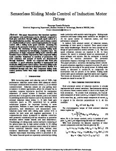
The following figure show ws the complete model of the sliding mode control of the induction motor:
εq (25)
Figure 1. Block diagram of Sliding Mode Control of an indction motor
IV.
REALIZATION OF SLIDING MO ODE CONTROL USING XILINX SYSTEM GENR RATOR
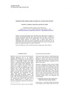
A. Structure System Generator is a DSP design tool from Xilinx that enables the use of the MathWorks modeel-based Simulink design environment for FPGA design. Preevious experience with Xilinx FPGAs or RTL design methoodologies are not required when using System Generator. Dessigns are captured in the DSP friendly Simulink modeling envvironment using a Xilinx specific blockset. All of the doownstream FPGA implementation steps including synthesis annd place and route are automatically performed to geneerate an FPGA programming file. Over 90 DSP build ding blocks are provided in the Xilinx DSP blockset for Simulink. These ng blocks such as blocks include the common DSP buildin adders, multipliers and registers. Also in ncluded are a set of complex DSP building blocks such as a forward error
correction blocks, FFTs, fiilters and memories. These blocks leverage the Xilinx IP I core generators to deliver optimized results for the seleected device. The functional model consistss of four main blocks: • A Sliding mode coontrol block: the block contains also four others subb-blocks: SMC2: The quadaratic component of stator current controoller SMC2 SMC4: The direct component of stator current controoller SMC3: The rotor r flux controller SMC1: The speed s Controller • The blocks of cooordinate’s transformation: the transformation of Park P Inverse (dq to αβ) • 2 Blocks for the Park P transformation (αβ to dq) • A block of the indduction motor in the alpha-beta coordinates
Figure 2. External view of the block diagram of Sliding Mode Control using XSG
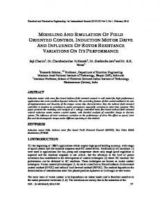
Figure 3. Internal view of the block diagram of Sliding Mode Controller using XSG
Figure 4. Internal view of the Sub-block SMC1 using XSG
B. Simulation results We present in this section a comparison between simulation results using XSG and simulation results using Simulink that is to say a comparison between discrete and continuous results. We suppose:
• Rotor speed reference: Wr* an echelon of speed which start at t=0.1s and a setpoint equal to 300(rad/s)). Table1. Sliding Mode control parameter
Kw 0.8
• Period of sampling; Te=50µs • Rotor flux reference: φr*=0.924Wb. Simulation results using XSG
Control parameters Kf Kd ε1 ε2 6 50 0.8 0.8
Kq 70
Simulation results using simulink
1
1
0.8
0.8
phirref
phirref
phird
0.4
0.4
0.2
0.2
0
0
-0.2 0
0.1
0.2
0.3
0.4
0.5 time(s)
0.6
0.7
0.8
0.9
phirq
0.6 Flux (Wb)
Flux (Wb)
phird
phirq
0.6
1
-0.2 0
Figure 5. dq axis rotor flux
0.1
0.2
0.3
0.4
0.5 time(s)
0.6
0.7
0.8
0.9
1
ε3 0.8
ε4 0.8
9
9
Isd
8
Is q
7
6
d-q axis stator cuurent(A)
d-q axis stator current (A)
7
5 4 3 2
6 5 4 3 2
1
1
0 -1 0
Is d
8
Isq
0.1
0.2
0.3
0.4
0.5 time(s)
0.6
0.7
0.8
0.9
0 0
1
0.1
0.2
0.3
0.4
0.5 time(s)
0.6
0.7
0.8
0.9
1
Figure 6. dq axis stator current 300
Wref
300
W 250
200
rotation speed(rad/s)
Rotation speed (rad/s)
250
150 100
200
150
100
50 50
0 -50 0
0.1
0.2
0.3
0.4
0.5
0.6
0.7
0.8
0.9
0 0
1
0.1
0.2
0.3
0.4
time(s)
0.5 time(s)
0.6
0.7
0.8
0.9
1
Figure 7. Response of rotation speed 25
25 Cem
Cem 20 Electromagnetic torque(N.m)
Electromagnetic torque (Nm)
20
15
10
5
10
5
0
-5 0
15
0.1
0.2
0.3
0.4
0.5 time(s)
0.6
0.7
0.8
0.9
0 0
1
0.1
0.2
0.3
0.4
0.5 time(s)
0.6
0.7
0.8
0.9
1
Figure 8. Electromagnetic torque(Cem) 10
6 4 2 0 -2 -4 -6 -8 0
Is alpha
8
Is beta Stator Current alpha-beta axis(A)
Stator Current alpha-beta axis(A)
10
Is alpha
8
Is beta
6 4 2 0 -2 -4 -6
0.1
0.2
0.3
0.4
0.5 time(s)
0.6
0.7
0.8
0.9
1
-8 0
Figure 9.αβ axis stator current
0.1
0.2
0.3
0.4
0.5 time(s)
0.6
0.7
0.8
0.9
1
1 0.8
0.6
0.6
0.4
0.4 Rotor flux(Wb)
Rotor flux in alpha-beta axis(Wb)
1 0.8
0.2 0 -0.2
0 -0.2 -0.4
-0.6
-0.6
-0.8
-0.8
0.1
0.2
0.3
0.4
0.5 time(s)
0.6
0.7
0.8
0.9
-1 0
1
phirbeta
0.2
-0.4
-1 0
phiralpha
0.1
0.2
0.3
0.4
0.5 time(s)
0.6
0.7
0.8
0.9
1
Figure 10.αβ axis rotor flux
After the simulation we conclude that all the results of current, speed torque, flux... obtained using simulink are identical to those obtained with XSG. That is to say that our objectif is reached. So we can use this Blockset to program our FPGA. V.
CONCLUSION
In this paper we have presented a new technique XSG that will serve us to implement our algorithm of sliding mode control of an induction motor on FPGA directly and without being obliged to make a difficult programming. In fact, we compared the results obtained using the XSG method and those obtained using simulink and we found the same results. Therefore, this technique is very important because we can save a lot of time to implement our algorithm, also, we can take advantage of benefits simulink to view real-time operation of our machine now just press Generate and we get the VHDL code that will be implemented on the FPGA board. REFERENCES [1]
[2]
[3]
[4]
[5] [6] [7]
[8] [9]
C. Lascu, I. Boldea, F. Blaabjerg, Direct torque control of sensorless induction motor drives: a sliding-mode approach, IEEE Transactions on Industry Appli-cations 40 (2) (2004) 582–590. F. Blaschke, The principle of field orientation applied to the new transvector closed loop system for rotating field machines, SiemensReview 39 (1972) 217–220. J. Li, Z. Hong, W. Yang, Application of variable structure theory to direct field-oriented induction motor speed controllers, in: International Workshop on Intelligent Systems and Applications, ISA, 2009, pp. 1–4. M.Y. Jang, B.S. Jang, J.I. Jeong, Y.H. Park, Y.A. Kwon, Speed sensorless control of induction motor using sliding mode observer with variable boundary layer, in: SICE Annual Conference, 2008, pp. 748– 752. H. Buhler, 1986. Réglage par mode de glissement, Presses Polytechniques Romandes, Lausanne,Suisse. Slotine, J. J., and Li, W. 1991. Applied nonlinear control. Englewood Cliffs, N: Prentice Hall. New York. Utkin, V. 1993. Sliding mode control design principles and applications to electric drives. IEEE Transactions on Industrial Electronics, 40, 2636. Krstic, M., Kanellakopoulos, I., Kokotovic, P., 1995. Nonlinear and Adaptive control design, wiley Inter-science Publication. A. Sabanovic, B. V. Izozimov "Application of sliding modes to induction motor control", IEEE Trans.Idust. Applic. Vol.IA 13.N°.1, pp.41, 1981.
[10] Zhiwen Ma, Trillion Zheng, Fei lin, Xiaojie You “A New Sliding-mode Current Controller for Field Oriented Controlled Induction Motor Drives”, Industrial Electronics Society (IECON). 31st Ann. Con. of IEEE Publication Nov. 2005.. [11] M.O.Mahmoudi, N.Madani, M.F.Benkhoris, and F. Boudjema, "Cascade sliding mode control of field oriented induction machine drive". The European Physical Journal. AP7, 217-225 (1999). [12] K. David Young, Vadim Utkin, and Umit Ozguner, "A Control Engineer's Guide to Sliding Mode Control," IEEE Transactions On Control System technology ,vol. 7, no.3, May 1999. [13] W. Perruquetti and J.P. Barbot, "Sliding mode control in engineering", Marcel Dekker, 2002. [14] W. Gao, "Variable Structure Control of Nonlinear Systems, A new Approach", IEEE Transaction on Industrial electronics, vol, 40, no. 1, 1993. [15] R. Ghosh-Roy, N. Olgac, "Robust Nonlinear Control via Moving sliding surface n-th order case", IEEE Conference on Decision & Control, USA 1997. [16] A. Benchaib et al, "Sliding mode Input-Output Linearization and Field Orientation for real-time control of induction motor", IEEE Transactions on power electronic, vo 1 14, no: 1, 1999. [17] W. Gao, "Variable Structure Control of Nonlinear Systems, A new Approach", IEEE Transaction on Industrial electronics, vol, 40, no. 1, 1993.