VLSI Architecture Design and Implementation of a LDPC Encoder for the IEEE 802.22 WRAN Standard Nelson Alves Ferreira Neto Joaquim Ranyere S. de Oliveira Universidade Federal da Bahia e Laboratorio de Sistemas integraveis e Tecnologicos Salvador, Bahia, Brazil Email:
[email protected]@gmail.com
Wagner Luiz A. de Oliveira Joao Carlos N. Bittencourt Universidade Federal da Bahia Salvador, Bahia, Brazil Email:
[email protected];
[email protected]
In this research a flexible hardware structure, based on the algorithm presented in [11] was designed in order to meet the functional requirements of WRAN LDPC systems. Compatible with the considered standard requirements, the proposed architecture can also realize other coding schemes by replacing the H matrices in its internal memory. The algorithm itself is not new, but the approach of serial and co-processor architectures aiming the flexibility required by the standard (84 operation modes) is the innovation of this work. This paper is outlined as follows: the Section II presents an overview of the IEEE 802.22 WRAN standard and how the parity verification matrices H are defined, as well as their adaptation to different code word lengths; in Section III the algorithm presented in [11] is highlighted, as well as the modifications proposed to make it in line with our architectures; in Section IV the proposed architectures are presented; the Section V presents the obtained results and the comparison with other solutions. The conclusions are discussed in Section VI.
Abstract-This paper presents two architectures for the Low Density Parity Check
(LDPC)
encoder, the first one based on a
fully serial approach and the second one in a mixed way, as well as their respective realizations in ASIC. The proposed designs are capable of operating in 84 combinations of code rate and word size, according to the IEEE 802.22 Wireless Regional Area Network
(WRAN)
standard, aiming low power and small area.
Although the proposed architectures are primarily designed for the mentioned standard, they can be easily adapted to other wireless broadband standards.
Keyowrds-LDPC; encoder; channel coding; 802.22; WRAN
I.
INTRODUCTION
Early Low Density Parity Check (LDPC) error correction codes were proposed by Gallager [1] in 1962, and only used decades later by MacKay [2] and Wiberg [3]. This method is considered one of the best error correction algorithms by providing excellent decoding performance and high throughput [4]. This category of algorithms operates near the Shannon limit [4][5], which is why it has been adopted by several recent communication standards such as DVB-S2, IEEE 802.16e, 802.11n and 802.22 [6, 7, 8]. The LDPC codes are defmed by sparse parity check matrices (H), generally represented by a Tanner graph, which can be used to decode the information received by a transmission channel. However, the direct coding process is obtained by multiplying the message by the generator matrix (G) that has high density. Such an approach turns its implementation for large codes unfeasible [9]. In [9] and [10] it was proposed a coding method based only on the matrix H. The LDPC code defined in IEEE 802.22 Wireless Regional Area Network (WRAN) standard was designed to take advantage of block-based modeling proposed in [9] and the hardware-driven algorithm presented in [11]. The flexibility required by the WRAN system for the LDPC encoding method demands twenty one code word lengths (ranging between 384 and 2304) and four different coding rates (1/2, 2/3, 3/4 and 5/6) [8]. Such a flexibility results in eighty four possible configurations for the WRAN LDPC encoding, which demands the development of an efficient based-WRAN hardware architecture, targeting low power and reduced silicon area. 9781467394192/15/$31.00 ©2015 IEEE
II. IEEE 802.22 WRAN The recent IEEE 802.22 WRAN standard establishes the LDPC as one of its possible channel encoders for cognitive radio. Such a standard was the first one for cognitive radio approved by IEEE and it was designed for communication in rural and remote areas with low population density, with cell radius about 30 km medium range, reaching 100 km in specific conditions [8]. The 802.22 standard was designed to operate in analog TV transmission spectrum (54-862 MHz) and can operate in 6, 7, or 8 MHz channels [12]. Due to the low popUlation density and the medium/long-range features, the channel conditions may vary significantly, which requires a high flexibility encoder in order to gather the best possible performance (higher throughput), ensuring the required redundancy for the posterior reconstruction of information. A. Structure ofParity Check Matrices
The IEEE 802.22 WRAN standard defines an m-by-n parity
71
B. Resizing Values in Hb
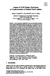
check matrix H for each code rate r= kin (1/2, 2/3, 3/4, and 5/6, respectively), where n is the code word length, m is the parity check length and k n - m is the systematic length (message to be transmitted) [8]. The code word vector is composed by the systematic part, the message bits, and the parity bits. The matrix H is structured based on arrangements of linear blocks, which are either zero valued or a set of permutation z by-z matrices Pi,j' as shown in Fig. l. Parity check matrices
All offset values for the base matrices in the IEEE 802.22 standard (Figures 2, 3, 4, and 5) are defined using the maxirnwn value for parameter z (zo 96). In such way, for a length n nb * z, n 24 * 96, n 2304. However the standard allows several code word sizes, as can be seen in Table 1, generating the need to resize the length of shifts when z is less than 96. The new values of the elements of Hb are defined by (1), taking l J as the floor operation.
=
=
=
are expanded from the base matrix Hb, mb-by-nb size, in which n nb * z and m mb * z. Figures 2, 3, 4, and 5 show the matrices Hb defmed by the WRAN standard. The conversion process of the matrix Hb in a matrix H is carried out by replacing each element in Hb by a square matrix Pi,j =
=
H=
PO,2
Pl,o
Pl,1
Pl,2
P2,o
P2,l
P2,2
Pmb-l,O
Pmb-l,l
Po,nb-2
Po,nb-l
Pl,nb-2
Pl,nb-l
P2,nb-2
Pmb-l,nb-l
Fig. 1: Matrix H defined by sets of permutation matrices or zeroes P;,j of size z-by-z.
1 94 73
1
1
1 27
1
1 22 79
1
1
1
1 55 83
1
1
7
0
1
1
1
1
1
1
1
1
1
9
1 12
1
0
0
1
1
1
1
1
1
1
1
0-1 -1
0
0-1 -1 -1 -1 -1 -1 -1 -1
1
1
-1 -1 -1 24 22 81-1 33-1 -1 -1
61-1 47-1 -1 -1 -1 -1 65 25-1 -1 -1 -1 -1
0
-1 -1 39-1 -1 -1 84-1 -1 41 72-1 -1 -1 -1 -1 -1 -1 -1 -1 46 40-1 82-1 -1 -1 79
0
0
1
1
1
1
7 65
1
1 94
1 59
1
1
1
1
1 70 72
1 39 49
1
1
0
2
1 19
1 47
1 48
-1 69-1 88-1 33-1
H" 1 36
0
0
1
1
1
1
1
1
1
1
0
0
1
1
1
1
1
1
1
1
1
1
0
0
7-1 -1 -1 -1 -1 -1 -1 -1 -1 -1
0
1 15
--1
3-1 16-1 37-1 40-1 48-1
0
0-1 -1 -1 -1 -1
10-1 86-1 62-1 28-1 85-1 16-1 34-1 73-1 -1 -1
1
0
1
1
1
0
0-1 -1 -1 0
1
1
1
0
0-1 0
0
1
1
1
1
1
0
0
1
1
1
1
0
0
1
1
1
71-1 55-1 12 66 45 79-1 78-1 -1 10-1 22 55 70 82-1 -1
0
0-1 -1
0 1 15
1
0
1 47
1 56
1 13
1 85
1 61
1
1 84
5
1
1 55
6
1 52
1 78
0-1 -1 -1 -1 -1
1
0 1
1 41 95
1
6 38
3 93
62 94 19 84 38 61-1 66
1
1
1 30 70
1 92 78
1 15
" 1 86 1
1 37 38
1 92
4 11
�
---
1 46 48
1 45 24 32 30
1
1
9 73 47 64-1 39 61 43-1 -1 -1 -1 95 32
-1 -1 -1 -1 32 52 55 80 95 22 -1 63 31 88 20-1 -1 -1
0-1 -1
0
6 51 24 90 44 20-1 -1 -1 -1 -1 -1
0-1 0
0 0
-1
4-1 91 84
" 8 86 52 82 33
....... ...-5
o 36 20
6-1 36 40 47 12 79 47-1 41 21 12 71 14 72
51 81 83
4 67
1 21
1 31 24 91 61 81
90 96 102 108 114 120 126 132 138 144
120 128 136 144 152 160 168 176 184 192
135 144 153 162 171 180 189 198 207 216
150 160 170 180 190 200 210 220 230 240
4 77 80
0 44 49
=
A. Algorithm
To handle with the problems of coding using generator matrix, we adopted the algorithm presented in [11] which makes possible to perform the encoding process using only the parity check code array H. As can be seen in Figures 2 to 5, the structure of parity check matrix defmed as Hb is divided into the sections Hb1 and Hb2, where the first colwnn of HbV in dark gray tone, contains only three non-null permutation matrices (PO,kb' P mb-1,kb and P x,kb ' with mb - 1 < x < 0), while the light
FIg. 4: Matnx Hb for code rate 3/4.
1 25 55-1 47
60 64 68 72 76 80 84 88 92 96
,, ---=:;..
6 40 56 16 71 53-1 -1 27 26 48-1 -1 -1 -1
...--
1440 1536 1632 1728 1824 1920 2016 2112 2208 2304
=
FIg. 3: Matnx Hb for code rate 2/3.
---
40 50 60 70 80 90 100 110 120 130 140
36 45 54 63 72 81 90 99 108 117 126
=
0-1 -1
1
1
0-1 30-1 74-1
1
0-1 -1 -1 -1
5-1 56-1 37-1 -1 -1
23-1 29-1 15-1 30-1 66-1 24-1 50-1 62-1 -1 -1 -1 -1 32
24 30 36 42 48 72 80 88 96 104 112
k ,=1/2 ,=1/2 ,=3/4 ,=5/6
The encoding process consists of the generation of a vector c - containing the code word - from a message vector u, where T c. H O. In this context, U is a binary word with k bits, c is the resulting coded word with n bits, and H is an m-by-n parity check matrix for a given LDPC code. The LDPC encoding can be performed using an k-by O. n generator matrix G, where c u. G and G. HT However, this approach may become impractical due to the fact that typically G is a dense matrix, making the coding complexity N2, where N n is the number of bits of the code word [13].
,, ----7
0
-1 30-1 65-1 54-1 14-1
24 30 36 42 48 54 60 66 72 78 84
z
=
1 95
-1 28-1 32-1 81-1 27-1 88-1
16 20 24 28 32 36 40 44 48 52 56
n
III. LDPC ENCODER
0-1 -1
1
1 47
384 480 576 672 768 864 960 1056 1152 1248 1344
k ,=1/2 ,=1/2 ,=3/4 ,=5/6
0-1 -1 -1
1
�
1 82
z
0-1 -1 -1 -1
Fig. 2: Matnx Hb for code rate 1/2.
---
n
0-1 -1 -1 -1 -1
12-1 -1 -1 83 24-1 43-1 -1 -1 51-1 -1 -1 -1 -1 -1 -1 -1 1
(1)
0-1 -1 -1 -1 -1 -1
0-1 -1 -1 -1
2-1 -1 47-1 -1 -1 -1 -1 -1 -1 -1 -1
43-1 -1 -1 -1 66-1 41-1 -1 -1 26
-1
othervalues
0-1 -1 -1 -1 -1 -1 -1
-1 -1 95 53-1 -1 -1 -1 -1 14 18-1 -1 -1 -1 -1 -1 -1 -1 11 73-1 -1 -1
*Z ,
Table I: Size of code words n, in bits, relative to the size z of the permutation matrix Pi, j, and k the systematic size, in bytes, according to the code rate r chosen.
P2,nb-l
Pmb-l,nb-2
Pmb-l,2
Hb
=
with size z. When the base matrix element value is -1, Pi,j will be a matrix of zeros; otherwise, the component will detennine Pi,j an identity matrix Iz circularly right shifted by a predefined value [8].
PO,l
=
Hb(i,j) {HbCil ,��)j),J Hb(i,j)
=
Po,o
=
H,, � 0-1 -1
0
0
0
0-1
9 86 78 60 88 67 15
1
1
0
50-1 50 15-1 36 13 10 11 20 53 90 29 92 57 30 84 92 11 66 80-1 -1
0
0
FIg. 5: Matnx Hb for code rate 5/6.
72
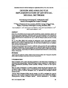
equations (13) and (14). Physically, the )'i values are stored in an exclusive volatile memory for the Pi values. For each Pi computation, Ai is discarded from the corresponding memory address. This implementation was possible due to the changes made in equation (14) to allow parity calculation from the end to the beginning, i.e., from Pmb-I to PI' Furthermore, as the last value to be computed in equation (8), )'mb-], is the first one to be used in equation (13), such an approach eliminates the need for reading and storing that value in memory. The general execution flow of the both hardware architectures is defmed by the state machine shown in Fig. 6. At the WAIT state the system is waiting and at the START one it is initialized with the received configuration settings. The ROW SUM state performs the process of scanning a row in HbZ and the information vector u, block by block, applying a circular left shift for each block Uj by a value Pi,j and accumulating the results. At the end of this process, the intermediate value Ai is obtained and at STORAGE AND CUMULATION state it is stored in the memory position of Pi and accumulated in Po. The iterative process between the states ROW SUM and STORAGE AND CUMULATION is done until all rows have been covered, (8) and (9). Since Po is calculated, the state CALC LAST PARITY controls the calculation of Pmb-i' (13), where Po is circularly shifted to
gray part is a double diagonal matrix, whose value is 0 for each element i j and i j+1, with i and j indexing rows and columns, respectively. This peculiarity of the 802.22 standard matrices allows the implementation of the encoding algorithm efficiently. Let the code word C [u,p] be the concatenation of the vectors U (message) and P (parity), with sizes k and m, respectively. By grouping vectors U and P in smaller sequences of length z, we have Cb Making [u,p] [uo,UV",Ukb-VPO,Pv ... Pmb-i]. Hb. Cb 0 in (2), equations (3), (4), (5), and (6) are defined. =
=
=
=
=
=
Po,o Pi.0
PO,l Pl,1
PO•kb
px•o
PX•i
Px,kb
Pmb-i•o
Pmb-i.i
Pmb-i.kb
Pi,kb
0
-1
0
0
-1 -1
-1
0
-1
-1
-1
0
",kb-1 + Pi,kb' Pi+Pi+l- 0, 1'- ° L.j=o Pi,j' Uj ",kb-1 +Pi+Pi+l1' * O,X,mb- 1 - 0, L.j=O Pi,j' Uj ",kb-1 ' - ° ,l-X L.j=o Pi,j,Uj+PO+Pi+Pi+l",kb-1 - ° ,l. - m b- 1 L.j=o Pi,j,Uj+ Pi,kb,Pi+Pi+l_
_
Uo ui Ukb-i =0 Po Pi Pmb-i
(2) (3) (4) (5) (6)
the right by the value in row and column mb - land kb then added with the intermediate value Amb-i' which was previously stored at the memory position Pmb-i' The state CALC PARITIES controls the calculation of remaining parities. These are calculated in a similar way to that done in the state CALC LAST PARITY, but the parity Pi+i is added too, (14). The other two states control the removal of parity and information data from the memory in the case of serial architecture.
Equation (7) can be used to find po and it is obtained by the sum of ( 3), (4), (5) and (6) in GF(2), where GF stands for Galois Field. As from the defmition of (8) it can then be rewritten (7), (3), (4), (5) and (6) by (9), (10), (11), (12), and (13) - these last used to create the parity vector. (7) (8) (9) (10) (11) (12) (13) The
Pi,j' Uj
operation can be implemented as a left circular
shift on the vector
Uj' Pi,j' Uj
=
Uj «< Pi,j'
where the
Pi,j
element of the matrix Hb defines the shift offset value. Since Pi,j,Uj 0 when Pi,j - 1 (zero matrix), equations (11) and (12) can be generalized in (14). =
=
Fig. 6: State machine with the LDPC encoding process flow.
(14)
IV.
Two architectures were developed, one considering direct memory access, and another with serial input of information bits to be encoded.
PROPOSED ARCHITECTURE
The hardware structures were designed in order to perform the encoding through the steps defined by equations (8), (9), (13), and (14) in an optimized way. During the execution of the first phase, in which the computation of po is carried out, the intermediate values corresponding to equation (8) are stored in a vector ). = [J.o, ).], . . . )'mb-I] to be used later into
A. Serial Architecture
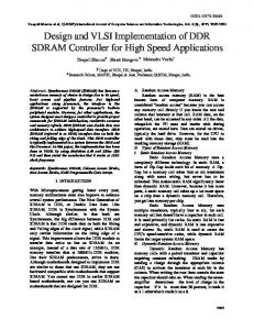
In the serial architecture shown on Fig. 7, the data are received and processed serially. Thus, the execution of each 73
iteration (8) uses a multiplexer and a demultiplexer to perform the circular left shift on the vector Uj' P i j' Uj Uj «< P i,j' , which uses less gates than a barrel-shifter. Instead of shifting and storing all bits of a block Uj at once, the data are added one by one and placed where they would be after shifting. The value which defines the shift size is obtained from the base matrix Hb in the ROM. These values defme the initial position of the multiplexer, then, for each new processed bit the offset value is incremented. In this architecture, unlike the coprocessor one, data in Hb, Fig. 8, are sequentially stored in the memory to allow access to all values in ascending order, row by row. For each set of systematic bits Uj is obtained a new value from Hb that
After the calculation of each row Ai the corresponding bits are stored in the memory to be used in the following calculations. Temporary values Ai use memory space reserved for parities, so that while each parity value is being calculated, the Ai is replaced by such value in the SRAM. Four-bit word size was chosen for the working memory because 4 is the greatest common divisor of all block sizes z defined in the standard, as shown in Table 2. This feature combined with the possible base matrices allows to achieve the flexibility in size and code rates demanded by the IEEE 802.22 WRAN standard. For this architecture it was used a 576x4 SRAM.
=
B.
This approach considers the scenario where the encoder is used as a coprocessor having shared memory access, i.e., the system memory is used to store the information to be encoded and the parity bits when they are ready. Thus, it is possible to eliminate the internal work RAM, since the information is directly processed with the system memory. The coprocessor architecture is shown in Fig. 9. Here, the values of base matrices Hb are also organized differently in the memory. The first change is that only valid shift information is stored, as the matrices are sparse - Figures 2-5, i.e., with a large amount of null elements. Hence, large part of the values need not be stored, decreasing the size of memory. Another positive factor about this organization is that addresses for each not null element into Hb are stored along with their elements - so, to calculate Ai, the hardware can go through just blocks ujwith shift not null. Thus, several cycles are saved.
indicates whether it will be added to compose the value Ai and which circular shift should be applied. Values from 0 to 96 indicate the size of shift and the value 97 represents the null value. For the storage of constants concerning the four parity check matrices, it was used a 512x7 ROM. As the systematic bits arrive serially, they are used to calculate A.1, with every four bits buffered on sram_inputJeg to be subsequently stored in the SRAM memory. These values are then used to calculate the remaining lines Ai, (8).
data in
I sram
I
input delay reg
Coprocessor Architecture
f-
input reg �-------i
� l ,----
.§
""
I
�
iil.1
II
sraminlerfacl.' 576)(4
Hbrom
+ Controller Shift
wo