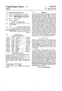
ABSTRACT. Novel quaternary half adder, full adder, and a carry-lookahead adder are introduced. The proposed circuits are static and operate in voltage-mode.
THE CIRCUIT DESIGN OF MULTIPLE-VALUED LOGIC VOLTAGE-MODE ADDERS I.M. Thoidis, D. Soudris, J. M. Fernandez* and A. Thanailakis Dept. Electrical and Computer Eng., Democritus University of Thrace, Xanthi 67100, Greece *
PHILIPS Semiconductors, System Lab, Software Group, SO15 0DJ Southampton, United Kingdom
ABSTRACT
2. Technological and designing issues
Novel quaternary half adder, full adder, and a carry-lookahead adder are introduced. The proposed circuits are static and operate in voltage-mode. Moreover, there is no current flow in steady states, and thus, no static power dissipation. Although the comparison in transistor count shows that the proposed quaternary circuits are larger than two respective binary ones, benefits in parallel addition arise from the use of multiple-valued logic. Firstly, the ripple-carry additions are faster because the number of carries are half compared to binary ones and the delay from the input carry through the output carry is relatively small. Secondly, the carry-lookahead scheme exhibits less complexity, which leads to overall reduction in transistor count for addition with large number of bits.
For simplicity, the voltage values coincide with the corresponding logical values. That is, 0, 1, 2 and 3 volts represent 0, 1, 2 and 3 logic levels, respectively. Both enhancement-mode and depletion-mode MOSFETs are used. The operation of the proposed circuits was verified by SPICE in 0.7 µm technology [7,8].
1. INTRODUCTION In the last two decades, Multiple-Valued Logic (MVL) has attracted the interest of researchers because of some critical features [2, 3]. The design of MVL circuits has covered a large spectrum, from simple operators’ circuits to arithmetic units. In particular, quite a few approaches were made for the implementation of adders using current-mode or mixed currentvoltage-mode circuits. Although some benefits arise from the latter approach, the disadvantage of the power consumption exists, due to the constant current flow. On the other hand, the presentation of adders operating in voltage-mode was poorer. Watanabe et al [10] proposed a dynamic half adder, using a charge-control technique similar to the pre-charge method of binary logic. However, the dynamic circuits suffer from known problems such as clock race, charge redistribution, etc. In this paper, novel quaternary half and full adder circuits, which operate in voltage-mode, are introduced. They are designed as functions, using operators that were presented in [6]. Also, an adder circuit for a quaternary carry-lookahead addition is presented. These adders are based on MOS technology and they do not exhibit power consumption during their steady states. Although these circuits have relatively large number of transistors, they exhibit some advantages in parallel addition. Assuming equivalent input numbers, the quaternary ripple-carry addition can be faster than the binary one. Also, the quaternary carry-lookahead addition can be achieved with fewer transistors, thus smaller circuit, for large numbers of digits.
0-7803-6685-9/01/$10.00©2001 IEEE
Watanabe proposed a pattern-generation method for a MVL function implementation [9,10]. Using this method, the truth table of a function can be considered as a concentration of logical-value patterns. More specifically, the method is carried out as follows. Applying the variables on the operators, matrices (representing truth tables) are produced, a step which might be further repeated with the variables and the previously obtained matrices. Next, the recognition of patterns, which are the identical with fractions of the final matrix (function’s truth table), inside all the produced matrices is made. Finally, the function’s truth table is composed using all the matrices in which patterns where recognized. In the following sections, the above method is used to construct both half and full adder as functions.
3. Quaternary voltage-mode adders 3.1 Quaternary half adder The proposed quaternary half adder is synthesized as a quaternary function. The operators, which are introduced in a previous work [6], are used to implement the circuit, which is depicted in Fig. 1. To understand the functionality of the introduced circuit, the logic levels for each node are given in a matrix form. The circuit construction through pattern generation method can be conceived if the matrices of the circuit are considered from right to left. The operator x b
3
is used with its
b
internal node, as it was previously defined [8]. Note that, both the carry Ci (where i=0,1,) and the complementary carry Ci signals are produced, which are both used as inputs to the input carry of the quaternary full adder. Eventually, 54 transistors are used for the half adder implementation of Fig. 1. To verify the exact function of the half adder, we used SPICE simulation, whose results are shown in Fig. 2. Consider that when the circuit reaches a stable state, there is no current path from a logic level (i.e. the corresponding voltage) to another. The worst case delay of the proposed half adder is 11.3 nsecs for the
IV-162
respectively. As shown in Fig. 3(a), the generate signal, gi, and delete signal, di, are inputs to output carry generation stage Fig. 3(b). Both signals are, also, useful for the implementation of the carry-lookahead adder, which will be explained in Section 4.
sum Si and 12.1 nsecs for the carry Ci. Consequently, the resulting circuit is a quaternary static voltage-mode half adder, with no static power dissipation.
1
[0 Ai
Bi 0 1 2 3
1 2 3]
0 1 2 3
1 2 3 1 2 3 2 2 3 3 3 3
1
0 0 0 0
3
3 3 3 3
0 0 0 3 3 3 3 3 3 3 3 3
3
1x =1x x
0 0 0 0
0 1 1 1
0 1 2 2
0 1 2 3
0 0 0 3 2
Input A Input B
3 0 1 2 3
0 0 3 0 0 3 0 0 3 3 3 3
min
2
0 y
0 = y2 3
1
x Θ1
2 3 3 3
3 3 3 3
0 0 0 0
0 0 0 1
0 0 0 2
min 0 0 0 0
0 1 2 3
min 0 1 2 3 max
0 0 0 0
1 2 3 2 3 3 3 3 3 3 3 3
0 0 0 0 0 1 0 1 2 1 2 3 0
0 y
1 3 3 3
max
max
min
3 3 3 3
0 0 0 0
0 0 0 0
0 0 0 1
0 0 1 2
0 1 2 3
Ci 3
ω0
1 2 3 0
2 3 0 0
min 3 0
3 3 3 3
3 3 3 0
3 3 0 0
3 0 0 0
0 1 2 3
1 2 3 0
2 3 0 1
3 0 1 2
max
2
1
Si
3 0 0 0 Ci
0 0
200
400
600 Time (µsecs)
(a)
0 0 0 0 0 0 0 1 1 0 1 2
Sum Carry (shaded area)
3
Figure 1. Quaternary voltage-mode half adder
3.2 Quaternary full adder A quaternary full adder adds two quaternary digits and an input carry, producing a quaternary sum and an output carry. These are, also, the values that the output carry follows. Since each quaternary digit equals the information quantity of two bits, the computational equivalent of a quaternary full adder is two binary ones in parallel. Similarly to the half adder, the full adder is designed as a quaternary function with the pattern generation method. Extending the half adder design, the circuit of Fig. 3(a) can be derived. The quaternary full adder circuit consists of the parts 0 3 given in Fig. 3(a) and 3(b). Both operators a x and x b are a
b
used with their internal nodes [8]. The logic levels are given in a matrix form for each node, and thus, the operation of the circuit is clear. Note that, the shaded matrices are produced when there is an input carry Ci-1. Moreover, both the output carry Ci and the complementary carry C i signals are generated. This is necessary, since conventional pass gates are used and both the input carry Ci-1 and the inverted carry C i −1 signals are needed. The resulting quaternary full adder consists of 78 transistors. In quaternary logic the three signals, namely delete signal, di, generate signal, gi, and propagate signal, pi, are can be introduced similarly to binary logic. Thus, delete, di, is produced for those pairs of inputs, Ai and Bi, that no output carry, Ci, is produced independently of the input carry, Ci-1. Generate, gi, is produced for those pairs of inputs, Ai and Bi, that an output carry, Ci, is produced independently of the input carry, Ci-1. Last, propagate, pi, is produced for those pairs of inputs, Ai and Bi, that the output carry, Ci, equals to the input carry, Ci-1. These signals can be seen in a matrix form in Fig. 3(a). Inside the proposed circuit generate signal, gi, and delete signal, di, are produced. Their low and high values are 0 and 3 logic level, respectively. These signals are equivalent to generate and delete signals of the conventional binary addition [4,5],
Sum Si and carry Ci (volts)
y ⊕1
2 2 3 3
Inputs Ai and Bi (volts)
1 2 3 3
2
1
0 0
200
400
(b)
600 Time (µsecs)
Figure 2. (a) The inputs of the quaternary half adder: Ai and Bi, and (b) the outputs: sum, Si, and carry, Ci, after SPICE. The total delay of a ripple-carry addition is proportional to the propagation delay from the input carry to the output carry and, also, proportional to the number of rippled carries [4]. In the full adder of Fig. 3, the input carry Ci-1 is applied close to the output carry Ci, which causes small propagation delay from Ci-1 to Ci. Furthermore, in a quaternary addition the rippled carries are half the number of that in a binary addition, considering that two bits are equals the information quantity of one quaternary digit. Consequently, quaternary ripple-carry addition for many digits is faster than the binary one.
4. Quaternary parallel addition using carrylookahead scheme As it was previously discussed, both the quaternary half and full adders were designed as functions. The fact that they were not designed in transistor level implies large circuits. Indeed, each of them has more transistors than two respective (half or full) binary adders. However, the overall transistor count is reduced to a parallel addition with the carry-lookahead scheme, when many digits are added. Consider a parallel binary addition with n (n=2k, where k=3, 4,…) bits for each summand. The operator “ ! ” was introduced [1] for the carry-lookahead addition as follows: ( g , p ) ! ( g ′, p ′ ) = ( g ∨ ( p ∧ g ′ ), p ∧ p ′ ) Also, assuming that:
IV-163
it stands: Gi = Ci . Using the above and, also, the associative property of the operator “ ! ”, the carry-lookahead addition can be realized as the block diagram in Fig. 5(a) shows. The structure of the carrylookahead block is well known [1,4,5]. Inside the carrylookahead block, the circuits of a typical cell implementing the “ ! ” operator are given in Fig. 5(b). In order to have compatibility with the proposed quaternary technology, it is assumed that the binary circuits have Vdd = 3 volts.
Input carry Ci-1 and inputs Ai and Bi (volts)
if i = 0 ( g 0 , p0 ) ( Gi , Pi ) = ( g , p ) ( G , P ) if 1 ≤ i ≤ n − 1 ! i −1 i −1 i i
Input A Input B Input carry (shaded area) 3
2
1
0 0
400
The delay for the carries estimation is proportional to log 2 n , the
number
of
cells
is
(n / 2) ⋅ log 2 n .
For
(n / 2) + (n / 4) − 1 number of cells, the derivation of the propagate signal, Pi, is not needed, and thus, these cells consist of 8 transistors only. The rest of them contain 14 transistors in total. A binary adder, which produces generate gi and propagate pi signals and then calculates the sum Si from propagate pi and input carry Ci-1 signals, requires 18 transistors. On the other hand, quaternary carry-lookahead addition is based on the same block diagram of Fig. 5(a). The carry-lookahead block is similar to that of the binary addition. The only difference is that, the inverter circuit for the Gi derivation of the cell that produces Cn −1 = S n must have Vdd = 1 volt, instead of 3 volts. This way the overflow Sn digit will have the correct quaternary value. In order to add the same numbers with the binary addition, n / 2 quaternary digits are necessary, and thus, (n / 4) ⋅ (log 2 n − 1) number of cells. (n / 4) + (n / 8) − 1 cells must produce only the generate Gi signal. The quaternary adder, constituted from the circuits of Fig. 3(a) and 3(c), produces generate gi and propagate pi signals and contains 76 transistors. Eventually, ignoring potential buffering for both implementations, the total transistor numbers N are: i) binary implementation: N b = 13.5 ⋅ n + 7 ⋅ n ⋅ log 2 n + 6 , and ii) quarternary implementation: N q = 35.75 ⋅ n + 3.5 ⋅ n ⋅ (log 2 n − 1) + 6 . The percentage of the transistor number variation is given by: ∆ = N b − N q N q ⋅ 100 % and it is plotted in Fig. 6. It can be noticed that, for small number n of input bits (32 bits and less), the binary implementation exhibits less hardware complexity than the corresponding quaternary ones. The hardware overhead ranges from 19% to 3%. For instance, in order to add two numbers of 8 bits, a binary carry-lookahead addition needs 19% less transistors than quaternary one, which adds two numbers of 4 quaternary digits. As the number of input bits grows up, the quaternary adder implementation becomes more hardware efficient than the equivalent binary design. For instance, a 256 bits binary carrylookahead addition requires 15.3% more transistors than the corresponding quaternary one.
1200 Time (µsecs)
Sum Output carry (shaded area) 3 Sum Si and carry Ci (volts)
while
800
(a)
2
1
0 0
400
800
(b)
1200 Time (µsecs)
Figure 4. (a) The inputs of the quaternary full adder: Ai, Bi and input carry, Ci-1, and (b) the outputs: sum, Si, and output carry, Ci, after SPICE simulation.
5. CONCLUSIONS Novel quaternary static voltage-mode adders, which do not consume power in steady state operation, were presented. These quaternary adders are larger compared to two respective binary ones. However, they can exhibit smaller delay in ripple-carry addition. Moreover, in the carry-lookahead addition benefits in overall transistor count arise for large numbers of added digits. Since the used operators are independent from the radix, both adders can be designed for higher arithmetic system bases by expanding the proposed quaternary circuits. This might extend the advantages of faster ripple-carry addition and further size reduction of the carry-lookahead circuit.
6. REFERENCES [1] Brent, P.R., Kung, H., A regular layout for parallel adders,” IEEE Trans. on Computers. C-31, 1982, pp.260-264. [2] Hurst, S., Multiple-valued logic - its status and its future. IEEE Trans. on Computers, C-33(12), 1984, pp.1160-1179. [3] Kameyama, M., Toward the age of beyond-binary electronics and systems. 20th International Symposium on Multiple Valued Logic, 1990, pp.162-166. [4] Rabaey, J.M. 1996, Digital Integrated Circuits: A Design Perspective, Prentice Hall Electronics and VLSI Series.
IV-164
pi (binary logic) or S0i and S1i (quaternary logic)
A2 B2
g2 p2
C1
gn-1
S2
Cn-2
pn-1
15
S1
...
Bn-1
C0
p1
...
... An-1
g1
Transistor number variation Δ (%)
B1
S0=S00
p0
Sum Si production block
A1
20
g0
Carry-lookahead block
B0
...
Generate gi and propagate pi production block
A0
Sn-1
Cn-1
Sn
(a) 3 3
10
5 32
64
96
128
160
192
224
256
0
Input bits (n) -5
-10
p
g'
-15
3
p'
p g ∨ ( g' ∧ p )
g
p ∧ p'
0 g ∨ ( g' ∧ p )
-20
3
p'
Figure 6. . Percentage of transistor number variation, ∆, between binary and quaternary carry-lookahead addition with respect to the number of input bits n.
p ∧ p'
p
0
g
p g'
[7] Thoidis, et al, Design methodology of multiple-valued logic voltage-mode storage circuits. In Proc.of Int. Symp. on Circuits and Systems, ISCAS ’98, 1998, pp. II, 125-128. [8] Thoidis, I., et al, The design of low power multiple-valued logic encoder and decoder circuits. In Proc. of 6th ICECS, 1999, pp. III 1623-1626. [9] Watanabe, T., Matsumoto, M., And Li T., New logical-sum and logical-product circuits using CMOS transistors and their applications to four-valued combinational circuits. Int. Journal of Electronics, 63 (2), 1987, pp. 215-227. [10] Watanabe, T., Matsumoto, M., And Li T., CMOS fourvalued logic circuits using charge-control technique. 18th Int. Symposium on Multiple-Valued Logic, 1988, pp. 90-97.
0 (b)
0
Figure 5. (a) Circuit of binary and quaternary carrylookahead addition. (b) Circuits of the cell, which implements the operator “ ! ” of the carry-lookahead block. [5] Smith, M.J.S. 1997, Application-Specific Integrated Circuits (U.S.A.:Addison-Wessley). [6] Thoidis, I. et al A., Quaternary voltage-mode CMOS circuits for Multiple-Valued Logic. IEE ProceedingsCircuits, Devices, and Systems, 145, 1998, pp.71-77. 12 22 33 33
y⊕ 1
33 33 33 33 max
1
00 03 03 03
1
1233 2333 3333 3333
00 33 33 33
di
3 0123 1123 2223 3333
0123
Ai
1
01 13 23 33
x 3 = 1x x max
max
23 33 33 33
3
33 33 30 30
3z 0 3
30 00 00 00
33 33 30 01
30 01 12 23
min
max
0
min
12 23 30 01
30 01 12 23
Ci-1
3 0
00 11 22 23
00 00 00 01
min
min
0003 0003 0003 3333
0 1 2 3
2
00 01 02 23
00 00 00 01
00 01 12 23
gi
max
3
0
0 y 0 = y2 0 2 y 3
0 3 ù 0
01 12 23 30
min 33 33 33 30
0 3
S1i
di
00 01 01 01
Bi
23 33 33 33
01 12 23 33
01 12 23 30
23 30 01 12
12 23 30 01
30 01 12 23
Ci-1
Si
23 30 00 00
S0i
max
33 30 00 00
01 12 23 30
23 30 01 12
gi 00 00 00 00
1
00 00 11 12
min
00 00 00 00
00 00 01 12
x⊗ 1
Generate and delete production 0 3
Sum production
(a)
Ci-1
0003 0030 0300 3000
Ci di 3 3 0
00 00 00 03
0 0 0 3
di
0 3 3 3
Ci-1
gi
pi
Propagate production
Ci 0
NOR
000 0 003 3 033 3 333 3
(c)
gi
(b)
Figure 3. . Quaternary voltage-mode adders: (a) and (b) full adder, (a) and (c) adder for carry-lookahead addition.
IV-165