Carpathian Journal of Electrical Engineering
Volume 12, Number 1, 2018
A MODIFIED VIRTUAL SPACE VECTOR MODULATION TECHNIQUE FOR Z-SOURCE NPC INVERTERS Francis EFFAH1, Philip OKYERE1, Patrick WHEELER2, Alan WATSON2, Jon CLARE2 1
Kwame Nkrumah University of Scince and Technology, Kumasi, Ghana, 2 University of Nottingham, Nottingham, UK.
[email protected]
Keywords: neutral point, voltage buck-boost, modulation, impedance network Abstract: A modified virtual space vector modulation approach for the control of a Zsource neutral point clamped inverter is presented in this paper. This approach works perfectly for the traditional neutral point clamped inverter. In this paper, the effectiveness of the virtual space vector modulation technique in balancing the input capacitor voltages of the Z-source NPC inverter with no low-frequency oscillations superimposed in addition to voltage buck-boost capability is demonstrated through simulations in SABER ®. A prototype converter is used to capture experimental results for validation.
1. INTRODUCTION Neutral-point-clamped (NPC) inverters are used in both medium-voltage high-power and low-power systems. Their popularity is attributed to merits like better harmonic performance, reduced switching losses, low dv/dt, smaller filter volume, and better electromagnetic compatibility [1]. Unfortunately, the ac peak output voltage that it can synthesize is always less than the input dc source. Thus in many applications a dc-dc boost converter is required at the input stage to meet the required output value. The resulting system becomes more complicated and its control can be difficult [2]. The Z-source NPC (ZNPC) inverter overcomes these limitations. The ZNPC inverter topology has received a lot of attention in the research community and is expected to find application in photovoltaic (PV) power systems [3]. It has also been explored for motor drive applications 99
Carpathian Journal of Electrical Engineering
Volume 12, Number 1, 2018
such as hybrid electric vehicles [4]. The ZNPC inverter adjustable speed drive (ASD) system has several unique advantages that are very desirable for many ASD applications, such as ride-through capability during sags, reduced line harmonics, improved power factor and reliability, and extending the output voltage range. However, this converter inherits one particular problem of the conventional NPC inverter: unbalanced input capacitor voltages [5, 6]. In many applications, well balanced capacitor voltages are required otherwise increased harmonics and damage of switching devices may result. As a result, there have been much efforts to solve the capacitor voltage balancing problem [7-9]. The capacitor voltage balancing control methods are grouped based on the pulse width modulation (PWM) methods. These include carrier-based sinusoidal PWM (CBSPWM) [10-12], space vector PWM (SVPWM) [8, 13-15], and selective harmonic elimination PWM (SHEPWM) [16]. SVPWM method offers low noise, small ripple, better dc utilization as well as easy implementation in a microcontroller [17] and therefore has attracted more attention. For the conventional three-level SVPWM, the capacitor voltages can be balanced through adjustment of the redundant small vectors' duration [5, 6, 9, 13, 18]. In [15], an SVPWM-based capacitor voltage controller that uses the direction of load currents was proposed. In this method, redundant voltage vectors were distributed to ensure small current flows through the neutral point (NP) so as to achieve capacitor voltage balance. The idea behind most SVPWM schemes is to select three nearest vectors to form the reference vector. However, these methods are not capable of balancing the capacitor voltages for high modulation index and low power factor [17]. Virtual space vector modulation (VSVM) was proposed to overcome this problem [19]. Several variants of the VSVM technique have been reported in the literature to balance the capacitor voltage of the conventional NPC inverter and some of its derived topologies [17, 19, 20]. Nevertheless, none of these techniques has been verified with the ZNPC inverter in the literature. This creates a research gap since the ZNPC inverter is expected to replace the NPC inverter in most applications where the dc source may not be constant but the output ac voltage needs to be controlled to obtain a favourable value for the load. In this paper the VSVM technique proposed in [19] for controlling the conventional NPC inverter is modified and applied to the ZNPC inverter to verify its effectiveness in modulating this converter. Applying this modified VSVM technique to the ZNPC inverter enables the inverter to perform voltage buck-boost function in addition to balancing input capacitor voltages with all low-frequency oscillations completely eliminated. The main advantage of the VSVM technique over the conventional SVPWM technique is its ability to eliminate completely low-frequency oscillations of the capacitor voltages. Capacitor voltage oscillation increases the voltage stress on power devices which may lead to premature failure of the converter. However, this benefit in capacitor voltage balance is achieved at the expense of an increased number of commutations compared to the 100
Carpathian Journal of Electrical Engineering
Volume 12, Number 1, 2018
conventional SVPWM strategy. The increase in commutations is due to the fact that the VSVM technique always employs five different switching states per switching cycle while the conventional SVPWM uses only four for high modulation index and majority of switching cycles. The additional commutations may lead to an increase in switching losses. In section 2, a brief review of the ZNPC inverter circuit is presented. The modified VSVM technique for controlling this converter is explained in section 3. Simulation as well as experimental results are presented in section 4 to verify the effectiveness of the VSVM technique in modulating the ZNPC inverter.
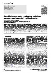
2. REVIEW OF Z-SOURCE NPC INVERTER Figure 1 shows the circuit configuration of the ZNPC inverter. The reference is taken as the neutral point, “o”. Each output phase leg has three values: Vi/2, 0, -Vi/2. With operation as a traditional NPC inverter, Vi equals 2VDC which is also the maximum output line-to-line voltage obtainable.
Fig. 1. Z-source NPC inverter
If shoot-through states are introduced into phase legs, an output line-to-line voltage greater than the available dc voltage can be obtained. Thus, ZNPC inverter can step down and step up the output voltage with a single stage structure. The ZNPC inverter can be operated either with full-shoot-through states or partialshoot-through states. In this work, partial-shoot-through method is selected since it produces output waveforms with better harmonic content [21]. 101
Carpathian Journal of Electrical Engineering
Volume 12, Number 1, 2018
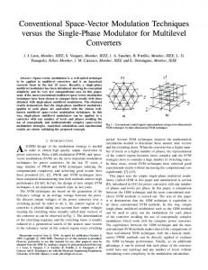
(a) NST state (b) UST state (c) LST state Fig. 2. Simplified representation of ZNPC inverter during (a) NST, (b) UST and (c) LST states
Figure 2 shows the simplified equivalent circuits of ZNPC inverter in different states. It is assumed the impedance network is symmetrical. Voltage equations for nonshoot-through (NST) states are given as: 𝑉𝐿1 = 2𝑉𝐷𝐶 − 𝑉𝐶2
(1)
𝑉𝐿2 = 2𝑉𝐷𝐶 − 𝑉𝐶1
(2)
𝑉𝑃 = +𝑉𝑖 /2
(3)
𝑉𝑁 = −𝑉𝑖 /2
(4)
𝑉𝑖 = 𝑉𝐶1 + 𝑉𝐶2 − 2𝑉𝐷𝐶
(5)
In a similar manner, voltage equations during upper-shoot-through (UST) states are given by: 𝑉𝐿1 = 𝑉𝐷𝐶
(6)
𝑉𝑃 = 0
(7)
𝑉𝑁 = 𝑉𝐷𝐶 − 𝑉𝐶1
(8)
and voltage equations for lower-shoot-through (LST) states are given as: 𝑉𝐿2 = 𝑉𝐷𝐶
102
(9)
Carpathian Journal of Electrical Engineering
Volume 12, Number 1, 2018
𝑉𝑃 = −𝑉𝐷𝐶 + 𝑉𝐶2
(10)
𝑉𝑁 = 0.
(11)
Let the switching period be Tsw and the combined time of shoot-through states be Tst. For symmetrical operation Tst is shared equally between UST and LST states. Performing inductor voltage averaging over one switching period, we have: 𝑉𝐶1 = 𝑉𝐶2 = 𝑉𝐶 = 2𝑉𝐷𝐶 . {
1−0.5𝑇𝑠𝑡 /𝑇𝑠𝑤 1−𝑇𝑠𝑡 /𝑇𝑠𝑤
}.
(12)
Using (12) and (5), the dc-link voltage for NST states is given as: 2𝑉𝐷𝐶
𝑉𝑖_𝑁𝑆𝑇 = 1−𝑇
𝑠𝑡 /𝑇𝑠𝑤
.
(13)
Similarly, putting (12) into (8) and (10), the dc-link voltage for UST and LST states are given by: 𝑉
𝑉𝑖_𝑈𝑆𝑇 = 𝑉𝑖_𝐿𝑆𝑇 = 1−𝑇 𝐷𝐶/𝑇 . 𝑠𝑡
𝑠𝑤
(14)
Obviously, the lower dc-link voltage occurs during LST and UST states when energy is stored in inductors according to (14). This energy is released to capacitors during NST states for voltage boosting. The fundamental ac peak output line-to-line voltage for the ZNPC is given by [21, 22]: 𝑉̂𝑙𝑙 = 𝑚𝐼 . 𝑉_𝑁𝑆𝑇 = 𝑚𝐼 . 𝐵. 2𝑉𝐷𝐶 ,
(15)
𝐵 = 1/(1 − 𝑇𝑠𝑡 /𝑇𝑠𝑤 ).
(16)
where
In (15), 𝑚𝐼 ≤ 1 represents the modulation index whiles 𝐵 ≥ 1 represents the boost factor.
3. MODIFIED VSVM APPLIED TO Z-SOURCE NPC INVERTER In this section, a modified VSVM strategy applied to the ZNPC inverter is presented. This modulation strategy is derived from the VSVM technique proposed in [19] which has
103
Carpathian Journal of Electrical Engineering
Volume 12, Number 1, 2018
been proved to work very well for the conventional NPC inverter. The VSVM technique in [19] was developed by modifying the conventional SVPWM strategy to mitigate the problem of unbalanced input capacitor voltages. For a conventional SVPWM strategy, the reference vector is formed by selecting three nearest vectors. At times more than one switching state can be used to generate a vector. In such situations a combination of these switching states is used for controlling capacitor voltages. Figure 3 shows the space vector diagram (SVD) with switching states and associated NP current for a conventional NPC inverter modulated using the conventional SVPWM strategy. The SVD is divided into six sectors (I to VI) and contain twenty-seven switching states classified as zero (V0), small (VS1 to VS6), medium (VM1 to VM6) and large (VL1 to VL6) vectors. Switching state ‘P’ means the top two devices of a phase leg are gated on, ‘O’ means the two middle devices are gated on while ‘N’ signifies the two bottom devices are turned on. If any output phase leg is in the ‘O’ state, there will be unequal charging/discharging of the top and bottom input capacitors. This leads to unequal capacitor voltages. To balance capacitor voltages effectively, it is required that average NP current in a switching cycle be zero. The conventional SVPWM technique is unable to achieve this because it uses the NP currents of small vectors to compensate those introduced by the medium vectors and it is not possible for the NP current introduced by the medium vectors to be fully compensated by those introduced by the small vectors. This is especially so when the modulation index is high and the power factor is low.
Fig. 3. Space vector diagram of conventional NPC inverter
104
Carpathian Journal of Electrical Engineering
Volume 12, Number 1, 2018
In the VSVM technique, a new set of virtual vectors is defined to balance the capacitor voltages effectively. These virtual vectors are formed by combining vectors associated with certain switching states of the SVD shown in fig. 3. Then the reference vector in each switching cycle is synthesized with nearest three virtual vectors. The virtual vectors formed have associated average NP currents equal to zero [1, 17, 19]. The virtual vectors for sector I are shown in fig. 4 where k5, k6, k7 ∈ [0, 1] and k5 + k6 + k7 = 1. Also k1, k2, k3, k4 ∈ [0, 1] with k1 + k2 = 1 and k3 + k4 = 1. The case shown in fig.4 represents the situation where k5 = k6 = k7 = 1/3 and k1 = k2 = k3 = k4 = 1/2.
VV0 is formed with V0, which obviously generates a NP current equal to zero because all output terminals are connected to an identical dc-link point, so there is no current flowing in the input capacitors.
VVSi are obtained from an equal combination of two switching states having the same associated NP current but opposite in sign. For example, if vector VVS1 is selected for a period of time tx, switching state ONN will be active for 0.5tx, and POO will be active for the remaining 0.5tx. Therefore, the average NP current during tx will be: 1 𝑡𝑥
(17)
VVMi are obtained from an equal combination of three switching states having an associated NP current equal to ia, ib and ic, respectively, and ia + ib + ic= 0. For instance, if vector VVM1 is selected for a period of time tz, switching state ONN will be active for 0.333tz, PON will be active for 0.333tz, and PPO will be active for 0.333tz. Therefore, the average NP current during tz will be: 1 𝑡𝑧
{0.5. 𝑡𝑥 . (𝑖𝑎 ) + 0.5. 𝑡𝑥 . (−𝑖𝑎 )} = 0
{0.333. 𝑡𝑧 . (𝑖𝑎 ) + 0.333. 𝑡𝑧 . (𝑖𝑏 ) + 0.333. 𝑡𝑧 . (𝑖𝑐 )} = 0
(18)
VVLi are obtained from the switching states that define VLi, all of them having an associated NP current equal to zero.
Fig. 4. Virtual space vectors for sector I
105
Carpathian Journal of Electrical Engineering
Volume 12, Number 1, 2018
The duty ratios of selected virtual vectors in a switching cycle can be calculated as: ⃗ 𝑜𝑢𝑡 𝑑𝑥 . 𝑉𝑉1 + 𝑑𝑦 . 𝑉𝑉2 + 𝑑𝑧 . 𝑉𝑉3 = 𝑉
(19)
𝑑𝑥 + 𝑑𝑦 + 𝑑𝑧 = 1
(20)
where 𝑉𝑉𝑗 corresponds to the jth selected virtual vector {j=1, 2, 3}. The duty cycles of different switching states forming the virtual vectors can then be determined. Finally, a decision of the application of different switching states over a switching cycle is made. The order of chosen switching states’ is such that connection of each phase to the dc-link points (p, o, n) is symmetrical. For instance, virtual vectors VVM1, VVL1 and VVL2 are selected to form the reference vector in triangle 4 of sector I. Using the VSVM technique, these virtual vectors are formed from VS1 (ONN), VS2 (PPO), VM1 (PON), VL1 (PNN) and VL2 (PPN). These vectors can then be applied to the output using the switching sequence: PPO PPN PON PNN ONN. For a switching period, Tsw, the active time of each vector is determined using (21) to (25). 𝑡1 [𝑃𝑃𝑂] = 𝑘7 . 𝑑𝑧 . 𝑇𝑠𝑤
(21)
𝑡2 [𝑃𝑃𝑁] = 𝑑𝑥 . 𝑇𝑠𝑤
(22)
𝑡3 [𝑃𝑂𝑁] = 𝑘6 . 𝑑𝑧 . 𝑇𝑠𝑤
(23)
𝑡4 [𝑃𝑁𝑁] = 𝑑𝑦 . 𝑇𝑠𝑤
(24)
𝑡5 [𝑂𝑁𝑁] = 𝑘5 . 𝑑𝑧 . 𝑇𝑠𝑤
(25)
In [19], the modification to the VSVM technique is seen in the switching sequence of the vectors applied to the output. The switching sequence is modified by introducing shoot-through states in phase legs of the ZNPC inverter for it to perform voltage buck-boost operation. Only the application of UST and LST states is considered in this work. An UST state means three top devices in a phase leg are turned on while a LST state represents turning on of three lower devices in a phase leg. A PWM switching sequence for achieving this goal is derived as discussed next. Consider switching sequence PPO PPN PON PNN ONN for a conventional NPC inverter. An UST state can be inserted in a phase leg provided it is in the “O” state and the other phases are in the “N” or “O” state otherwise there will be a collapse of the output line-to-line voltages. In a similar way, a LST state can be inserted in a phase
106
Carpathian Journal of Electrical Engineering
Volume 12, Number 1, 2018
leg if it is in the “O” state and the other two phases are in the “P” or “O” state [21]. Based on this reasoning, a LST state is introduced next to PPO (PPL) since this will not affect the output line-to-line voltage. Similarly, an UST is introduced next to ONN (UNN) with no adverse effect on the output line-to-line voltage. No UST or LST state can be introduced next to PON because that will breach the condition for insertion of shoot-through states. The resulting modified PWM sequence for the ZNPC inverter is shown in fig. 5 for triangle 4 of sector I.
Fig. 5. Example VSVM switching sequence for the ZNPC inverter
4. RESULTS AND DISCUSSION A simulation exercise in SABER® was undertaken to verify the modified VSVM technique for controlling the ZNPC inverter. The simulation results have been validated experimentally with a laboratory prototype. The parameters used for the simulation and experimental studies are presented in Table 1. Table 1. Parameters used for simulation and experimental studies
Symbol
Description
Value
2VDC
Input dc voltage
120 V
Cup, Cdn
Input capacitors
100 μF
L1,2
Inductors for Z-source network
1 mH
C1,2
Capacitors for Z-source network
470 μF
Lload
Load inductance
20 mH
Rload
Load resistance
10 Ω
fout
Output frequency
50 Hz
fsw
Switching frequency
5 kHz
4.1. Simulation results The main contribution of this paper is the balancing of input capacitor voltages to eliminate low-frequency oscillations in a ZNPC inverter. The ability of this converter to perform voltage buck-boost function with the introduction of shoot-through states is also demonstrated. These are shown through simulation analysis presented next.
107
Carpathian Journal of Electrical Engineering
Volume 12, Number 1, 2018
The circuit diagram of the model used for the simulations as well as the experimental validation is shown in fig.1. The converter is supplied with a dc voltage of 120 V via two series connected input capacitors. A Z-source network comprising two inductors, two capacitors and two diodes connects the input capacitors to the NPC circuit. The NPC circuit comprises three phase legs with each leg consisting of four IGBTs with anti-parallel diodes and two clamping diodes. An R-L load consisting of 10 Ω resistors and 20 mH inductors was used. The ZNPC inverter was initially operated as a conventional NPC inverter using the VSVM technique described earlier with a modulation index of 0.9 and shoot-through ratio of 0, respectively. With this mode of operation, the output line-to-line voltage is expected to have a fundamental component of 0.9 x 120 = 108 V. This is obvious as shown in fig. 6 (a) with a peak fundamental component of 106.6 V. 150
150
Line-to-line voltage (V)
Line-to-line voltage (V)
X: 50 Y: 132
100
X: 50 Y: 106.6
50
0
0
2000
4000 6000 8000 Frequency (Hz)
10000
50
0
12000
(a) FFT of line-to-line voltage, see (15)
0
-200 0.5
Line-to-line voltage (V)
0
-200 1.5
0.51
0.52 Time (s)
0.53
1.52 Time (s)
1.53
1.54
(b) Line-to-line voltage
2
2
1
1
Load phase currents (A)
Load phase currents (A)
1.51
0.54
(b) Line-to-line voltage
0
0 -1
-1 0.51
0.52 Time (s)
0.53
-2 1.5
0.54
(c) Load phase currents
1.51
1.52 Time (s)
1.53
1.54
(c) Load phase currents 61 Vc up Vc dn
60.5 60 59.5
0.51
0.52 Time (s)
0.53
(d) Input capacitor voltages
0.54
Input capacitor voltages (V)
61 Input capacitor voltages (V)
12000
-100
-100
108
10000
X: 1.502 Y: 146.6
100
X: 0.5022 Y: 118.7
0
59 0.5
4000 6000 8000 Frequency (Hz)
200
100
-2 0.5
2000
(a) FFT of line-to-line voltage, see (15)
200
Line-to-line voltage (V)
100
Vc up Vc dn
60.5 60 59.5 59 1.5
1.505
1.51 Time (s)
1.515
(d) Input capacitor voltages
1.52
Carpathian Journal of Electrical Engineering
Volume 12, Number 1, 2018
160 X: 0.5134 Y: 118.7
119
ZNPC inverter dc-link voltage (V)
ZNPC inverter dc-link voltage (V)
120
118 117 116 115 0.5
0.51
0.52 Time (s)
0.53
0.54
(e) DC-link voltage seen by NPC circuit, see (13) Fig. 6. Simulation results for voltage-buck operation
140
X: 1.5 Y: 146.2
120 100 80 60 1.5
1.5002
1.5004 1.5006 Time (s)
1.5008
1.501
(e) DC-link voltage seen by NPC circuit, see (13) and (14) Fig. 7. Simulation results for voltage-boost operation
The dc-link voltage appearing at the output of the Z-source network is clearly not stepped up and the output line-to-line voltage has a peak value of 118.7 V (fig. 6(b)) taking into consideration the voltage drops in the diodes. The corresponding load currents are shown in fig. 6(c). The voltages of the input capacitors are also shown in fig. 6(d) where it is noted that they are well balanced with no low-frequency oscillations superimposed on them. Similarly, the dc-link voltage seen by the NPC inverter circuit stands at 118.7 V as expected (fig. 6(e)). For voltage-boost operation, shoot-through states are inserted into selected phase legs as described earlier. Here the modulation index is maintained at 0.9 while shootthrough ratio is set to 0.2. This gives a boost factor of 1/0.8 (= 1.25) and hence the peak fundamental output line-to-line voltage expected is 108 x 1.25 (= 135 V). Figure 7 shows the boosted waveforms. The FFT of the output line-to-line voltage shows a fundamental value of 132 V (fig. 7(a)). A boosted dc-link voltage of 146.6 V is shown in fig. 7(b). The corresponding boosted load currents are shown in fig. 7(c). The input capacitor voltages are shown in fig. 7(d) where it is clear that they are well balanced with all low-frequeny oscillations eliminated completely. The Z-source network output voltage is shown in fig. 7(e). This clearly shows two levels of 146.2 V and 73.1 V, respectively, in accordance with (13) and (14). 4.2. Experimental results To validate the simulation work carried out in section 4.1 an experimental prototype converter was set up. A 120 V dc supply was used to power the ZNPC inverter. The Zsource network comprises two inductors and two capacitors connected in an X-shape between the dc source and the back-end NPC circuit. The NPC circuit consists of three APTGL60TL120T3G NPC modules comprising four series-connected IGBTs with antiparallel diodes and two clamping diodes. Heat sinks are attached to the IGBT modules for cooling purposes. Converter modulation is implemented using a DSP and an FPGA with a
109
Carpathian Journal of Electrical Engineering
Volume 12, Number 1, 2018
series of circuits which allow information such as gate drive signals and measurement signals to be transferred to and from the power PCB board. Figure 8 shows a schematic of the entire system used for the converter control. Experimental results were taken with a LeCroy Waverunner 6050 oscilloscope using a combination of differential voltage and current probes. First, a buck mode of operation was commanded by using a modulation index and shoot-through ratio of 0.9 and 0 respectively. For this mode, the expected peak value of the fundamental output line-to-line voltage is limited to 0.9 x 120 (= 108 V). Figure 9(a) shows the experimental waveform for this condition with an actual value of 105 V. It is clearly seen that this matches well with the simulation result presented earlier. Figure 9(b) shows the output line-to-line voltage where a peak value of 117.7 V is recorded. The corresponding load currents are shown in fig. 9(c). This result matches well those shown in fig. 6(c). The waveforms for the input capacitors are shown in fig. 9(d). The result clearly shows balanced capacitor voltages with no low-frequency oscillations. Finally, fig. 9(e) shows the ZNPC inverter dc-link voltage which obviously matches that of simulation shown in fig. 6(e).
Fig. 8. Schematic of experimental set up
To command voltage-boost operation, the modulation index was maintained at 0.9 while the shoot-through ratio was set to 0.2. The boosted waveforms are shown in fig. 10. In these plots, we observe that there is a close matching with the simulation results. Figure 10(a) shows the boosted fundamental output line-to -line voltage with a peak value of 129.9 V. The corresponding output line voltage is shown in fig. 10(b). The associated boosted currents are shown in fig. 10(c), while the input capacitor voltages are shown in fig. 10(d), respectively. The boosted ZNPC inverter dc-link voltage is also presented in fig. 10(e).
110
Carpathian Journal of Electrical Engineering
Volume 12, Number 1, 2018
These results clearly confirm effectiveness of the VSVM algorithm in balancing the input capacitor voltages of the ZNPC inverter in addition to voltage buck-boost operation. 150
100
Line-to-line voltage (V)
Line-to-line voltage (V)
150
X: 50 Y: 105
50
0
0
2000
4000 6000 8000 Frequency (Hz)
10000
12000
50
0
(a) FFT of line-to-line voltage, see (15) 150
150
100
100
50 0 -50
0.01
0.02 Time (s)
0.03
0
Load currents (A)
Load phase currents (A)
0 -1
0.01
0.02 Time (s)
0.03
0.02 Time (s)
0.03
0.04
1 0 -1 -2 0.0
0.04
0.01
0.02 Time (s)
0.03
0.04
(c) Load phase currents
65
65 Vc up Vc dn
60
0.01
0.02 Time (s)
0.03
Input capacitor voltages (V)
Input capacitor voltages (V)
0.01
2
(c) Load phase currents
60 57.5 55 0
0.04
Vc up Vc dn
62.5
(d) Input capacitor voltages
0.01
0.02 Time (s)
0.03
0.04
(d) Input capacitor voltages
120
160
115
ZNPC dc-link voltage (V)
ZNPC inverter dc-link voltage (V)
12000
(b) Line-to-line voltage ia ib ic
1
110 105 100 0
10000
-50
-150 0
0.04
2
55 0
4000 6000 8000 Frequency (Hz)
50
(b) Line-to-line voltage
-2 0
2000
-100
-100 -150 0
0
(a) FFT of line-to-line voltage, see (15)
Line-to-line voltage (V)
Line-to-line voltage (V)
X: 50 Y: 132
100
0.01
0.02 Time (s)
0.03
0.04
(e) DC-link voltage seen by NPC circuit, see (13) Fig. 9. Experimental results for voltage-buck operation
140 120 100 80 60 0
0.0005 0.001 0.0015 0.002 0.0025 0.003 0.0035 0.004 Time (s)
(e) DC-link voltage seen by NPC circuit, see (13) and (14) Fig. 10. Experimental results for voltage-boost operation
111
Carpathian Journal of Electrical Engineering
Volume 12, Number 1, 2018
5. CONCLUSIONS A modified virtual space vector modulation approach used to control a Z-source neutral point clamped inverter has been presented. The ability of this converter to perform voltage buck-boost function has been verified. Balancing of the input capacitors of this converter by the modified virtual space vector modulation technique has also been confirmed through simulations and validated experimentally. The approach used here is superior to the conventional SVPWM in balancing the input capacitor voltages by eliminating completely all low-frequency oscillations on the capacitor voltages which may lead to premature failure of the converter. This benefit is however achieved at the expense of more switching commutations. REFERENCES [1]
[2]
[3]
[4] [5]
[6]
[7]
[8]
[9]
112
X. Wu, G. Tan, Z. Ye, G. Yao, Z. Liu, and G. Liu, Virtual-Space-Vector PWM for a ThreeLevel Neutral-Point-Clamped Inverter with Unbalanced DC-Links, IEEE Trans. Power Electron., vol. 33, no. 3, pp. 2630-2642, Mar. 2018. X. Li, W. Zhang, C. Du, X. Wu, and D. Xu, Neutral point voltage control for three-level fuel cell power conversion system, in Proc. 2nd IEEE Int. Symp. Power Electron. Distrb. Gen. Syst., pp. 122-128, Jun. 2010. H. Abu-Rub, A. Iqbal, S. Moin Ahmed, F. Z. Peng, Y. Li, G. Baoming, Quasi-Z-source inverter-based photovoltaic generation system with maximu power tracking control using ANFIS, IEEE Trans. Power Electron., vol. 4, no. 1, pp. 11-20, Jan. 2013. O. Ellabban, J. V. Mierlo, P. V. den Bossche, Z-source inverter for vehicular applications, in Proc. IEEE Vehicular Power and Propulsion Conference (VPPC), pp. 1-6, 6-9 Sept. 2011. W. Chen, H. Sun, X. Gu, and C. Xia, Synchronized space-vector PWM for three-level VSI with lower harmonic distortion and switching frequency, IEEE Trans. Power Electron., vol. 31, no. 9, pp. 6428-6441, Sep. 2016. Y. Zhang, J. Li, X. Li, Y. Cao, M. Sumner and C. Xia, A method for the suppression of fluctuations in the neutral-point potential of a three-level NPC inverter with capacitorvoltage loop, IEEE Trans. Power Electron., vol. 32, no. 1, pp. 825-836, Jan. 2017. A. Choudhury, P. Pillay, and S. S. Williamson, Modified dc-bus voltage balancing algorithm for three-level neutral-point-clamped (NPC) IPMSM drive for electric vehicle applications, IEEE Trans. Ind. Electron., vol. 63, no. 2, pp. 761-772, Feb. 2016. A. Choudhury, P. Pillay, and S. S. Williamson, DC-Bus voltage balancing algorithm for three-level neutral-point-clamped (NPC) traction inverter drive with modified virtual space vector, IEEE Trans. Ind. Appl., vol. 52, no. 5, pp. 3958-3967, May. 2016. J. Lyu, W. Hu, F. Wu, and K. Yao, Three-level saddle space vector pulse width modulation strategy based on two-level space vector pulse width modulation for neutral-point-clamped
Carpathian Journal of Electrical Engineering
[10]
[11]
[12]
[13]
[14] [15]
[16]
[17]
[18]
[19]
[20]
[21]
[22]
Volume 12, Number 1, 2018
three-level inverters, IET Power Electron., vol. 9, no. 5, pp. 874-882, Sep. 2016. Z. Mohzani, B. P. McGrath, and D. G. Holmes, A generalized natural balance model and balance booster filter design for three level neutral point clamped converters, IEEE Trans. Ind. Appl., vol. 51, no. 6, pp. 4605-4613, Nov. 2015. K. Wang, L. Xu, Z. D. Zheng, and Y. Li, Capacitor voltage balancing of a five-level ANPC converter using phase-shifted PWM, IEEE Trans. Power Electron., vol. 30, no. 3, pp. 11471156, Mar. 2015. A. Videt, P. L. Moigne, N. Idir, P. Baudesson, and X. Cimetiere, A new carrier-based PWM providing common-mode current reduction and DC-bus balancing for three-level inverters, IEEE Trans. Ind. Appl., vol. 54, no. 6, pp. 3001-3011, Dec. 2017. Y. Jiao, F. C. Lee, and S. Lu, Space vector modulation for three-level NPC converter with neutral point voltage balance and switching loss reduction, IEEE Trans. Power Electron., vol. 29, no. 10, pp. 5579-5591, Oct. 2014. G. J. Tan, Q. W. Deng, and Z. Liu, An optimized SVPWM strategy for five-level active NPC (5L-ANPC) converter, IEEE Trans. Power Electron., vol. 29, no. 1, pp. 386-395, Jan. 2014. B. Jacob, M. R. Baiju, A new space vector modulation scheme for multilevel inverters which directly vector quantize the reference space vector, IEEE Trans. Ind. Electron., vol. 62, no. 1, pp. 89-95, Jan 2015. S. R. Pulikanti, M. S. A. Dahida, and V. G. Agelidis, Voltage balancing control of three-level active NPC converter using SHE-PWM, IEEE Trans. Power Del., vol. 26, no. 11, pp. 258-267, Jan. 2011. C. Hu, X. Yu, D. G. Holmes, W. Shen, Q. Wang, F. Luo, and N. Liu, An improved Virtual Space Vector Modulation Scheme for Three-Level Active Neutral-Point-Clamped Inverter, IEEE Trans. on Power Electron., vol. 32, no. 10, pp. 7419-7434, Oct. 2017. A. R. Beig, S. Kanukollu, K. A. Hosani, and A. Dekka, Space-vector-based synchronized three-level discontinuous PWM for medium-voltage high-power VSI, IEEE Trans. Ind. Electron., vol. 61, no. 8, pp. 3891-3901, Aug. 2014. S. B. Monge, J. Bordonau, D. Boroyevich, and S. Somavilla, The nearest three virtual space vector PWM – a modulation for the comprehensive neutral-point balancing in the three-level NPC inverter, IEE, Power Electronics Letters, pp. 11-15, 2004. S. W. Gui, Z. J. Lin, and S. H. Huang, A varied VSVM strategy for balancing the neutralpoint voltage of dc-link capacitors in three-level npc converters, Energies, vol. 8, no. 3, pp. 2032-2047, Aug. 2015. F. B. Effah, P. Wheeler, J. Clare, and A. Watson, Space-Vector-Modulated Three-Level Inverters With a Single Z-Source Network, IEEE Trans. Power Electron., vol. 28, no. 6, pp. 2806-2815, Jun. 2013. P. C. Loh, F. Gao, F. Blaabjerg, and S. W. Lim, Operational analysis and modulation control of three-level Z-source inverters with enhanced output waveform quality, IEEE Trans. Power Electron., vol. 24, no. 7, pp. 1767-1775, Jul. 2009.
113