Preprints of the 18th IFAC World Congress Milano (Italy) August 28 - September 2, 2011
An Approach to use MDE in Dynamically Reconfigurable Networked Embedded SOAs M. Marcos*. E. Estévez†, C. Jouvray**, A. Kung** *Dept. Ingeniería de Sistemas y Automática. ETSI Bilbao, UPV/EHU; e-mail:
[email protected] †Dept. Ingeniería Electrónica y Automática EPS de Jaén, email:
[email protected] **Trialog, France e-mail: (antonio.kung, christophe.jouvray) @trialog.com Abstract: Integration, reuse, flexibility and adaptability are some of the characteristics demanded by current complex embedded applications in order to adapt to a rapidly changing and competitive market. Besides, commonly they must be distributed in open and heterogeneous environments and able to be flexible enough in order to cope with dynamic changes of its environment (dynamic reconfiguration). Model Driven Engineering (MDE) is a software development methodology that promotes an intensive use of models, or abstractions, to cope with the complexity inherent to the application design. This paper proposes a modelling approach, in the context of the ARTEMIS iLAND project, for networked embedded service oriented applications, having specific dynamic reconfiguration requirements assuring an optimum usage of the limited system resources. The modelling approach focuses on the definition of models and model transformations, from the application requirements to code generation, emphasizing dynamic reconfiguration of the application. Keywords: Model Driven Engineering , Networked Embedded Systems, Dynamic Reconfiguration 1. INTRODUCTION An embedded system (Zurawski, 2005) (Henzinger, 2008), (Kopetz, 2008), is composed of hardware and software parts and it evolves in a real world environment. This kind of systems is used in automotive, aerospace, military, and health care domains, among others. Additionally, an embedded system is commonly not monolithic but interacts with other systems through a network. Currently, available middleware are widely used to hide communications between different nodes of the system. Moreover, the complexity is abstracted thanks to a clear separation of concerns inherent to well-known component or service based solutions. In particular, for real-time embedded systems, some solutions exist such as FCM (Jan et al 2010), (eC3M, 2003), FRACTAL (E. Bruneton, et. al., 2006), lwCCM (OMG, 2006a, 2006b), (AADL, 2002). eC3M (embedded Component Container Connector) middleware is component-based approach for embedded systems that relies on several OMG’s standards like CCM and MARTE UML profile. The approach covers all the product life cycle from the requirements to the application deployment. However, reconfiguration mechanisms are limited and the determinism of the reconfiguration phases is not proved. Moreover, the reconfiguration must be done programmatically (a dedicated component is in charge on it). to the difference with the approach of this paper. In order to achieve a level of quality of service (QoS), the overall system may need to be reconfigured dynamically. This is the main goal of the ARTEMIS iLAND project which Copyright by the International Federation of Automatic Control (IFAC)
focuses on the development of a middleware for deterministic dynamically reconfigurable networked systems using the concepts of service oriented architectures. The design of such systems is very complex. Additionally, in a real-time context, the reconfiguration must be achieved in deterministic way. The standard solutions mentioned above are not sufficient. In this context, Model-Driven Engineering (MDE) technologies offer a promising approach to address the complexity of platforms as well as to express domain concepts effectively. In this paper, a model-based approach is used to represent the system, emphasizing dynamic reconfiguration of the application. The ultimate goal is to generate code for the iLAND platform from the application requirements and by means of model transformations. The layout of the paper is as follows: Section 2 presents the ARTEMIS iLAND project in which this work is performed. Section 3 is dedicated to the modelling approach for iLAND applications focusing on reconfiguration issues. In section 4 an illustrative case study of reconfiguration in the Healthcare domain is presented. The paper ends with some conclusions and future work. 2. THE ARTEMIS iLAND PROJECT ILAND stands for “mIddLewAre for deterministic dynamically reconfigurable NetworkeD embedded systems”. The main objective of the project consists of developing a component-based middleware framework capable of supporting deterministic dynamic functional composition and reconfiguration of distributed applications (García-Valls and Gómez-Molinero 2010). As a result, an improvement on
14946
Preprints of the 18th IFAC World Congress Milano (Italy) August 28 - September 2, 2011
system flexibility, scalability, and composability will be achieved. Also, maintainability will be improved since spontaneous reconfiguration of the system will be supported. This will enable dynamic functionality reconfiguration, e.g. node activation, removal of crashed or damaged nodes and reallocation of functionality. The middleware is being applied to three different real application domains: (1) A high-availability video surveillance application. In this case iLAND must allow reconfiguring the functionality inside the nodes as well as the nodes themselves without interrupting the operation at any time; (2) Health-care applications. In this context, buildings are equipped with a number of sensors, actuators and distributed hosts that share information; and (3) Earlyenvironmental detection applications through public infrastructure. These applications are based on selforganizing sensor islands that collect environmental data and share them with the outside world via opportunistic networks. Notwithstanding this, one of the purposes of the resulting middleware is that it must be general enough to be applied to other application types and domains. 3. DOMAIN MODELS FOR iLAND APPLICATIONS Models help in understanding a complex problem and its potential solutions through abstraction. One of the major advantages of the modelling approach is that models are expressed using concepts that belong to a specific problem domain. In order to give full support to the life cycle of iLAND applications, a set of cooperating models must be defined as well as model transformations that guide the life cycle of applications, from the specification to the automatic code generation while supporting run-time reconfiguration using networked embedded service oriented architectures. In this context, a service is software entity, with well and selfdefined interfaces, that provides specific functionality. A specific service repository can be created for each application domain. A service can have associated several implementations, having each one specific need of resources (required QoS) and offering each one specific QoS to the application (provided QoS). Each implementation is a selfcontained entity that receives and sends messages and that is located at a specific point in the system architecture. A Service Oriented Application (SOA) is then specified as a service-graph, i.e. a set of services that co-operate to achieve the functionality and having a set of non-functional requirements. One of the goals of the iLAND middleware is to be able to dynamically assign resources to applications in order to fulfil both functional and non-functional requirements. This means to select the appropriate service implementations, located in specific nodes that do not influence the fulfilment of requirements for the applications already running on the system. Note that this decision may imply changing the service implementations of other SOAs, i.e. its corresponding execution graph. Thus, if a new application is launched or an existing one needs reconfiguration, the iLAND middleware must assign resources dynamically. It is then necessary to
characterize the resources that SOAs share: the hardware resources in terms of processor power, memory, energy, network bandwidth, etc., the software resources in terms of operating system mechanisms for concurrency and time management, device drivers, etc and finally, the set of available services to compose applications. Service characterization is defined in terms of its functionality and the available implementations, specified by their required and provided QoS requirements. On the other hand, the definition of a SOA must be characterized as a service-graph where a set of services collaborate through data exchange. This graph should express reconfiguration issues to be handled at run-time. Additionally, the SOA may have QoS requirements. Finally, SOA characterization at run-time, where applications consist of a set of threads, located in specific nodes, executing service implementations which exchange messages through network segments or through shared memory, must contain enough information for, jointly with the particularities of the platform, generating and starting up the application at run-time. The following sub-sections are devoted to the definition of a Meta-Model for the three views. Prior to this, the set of elements used in every view is characterized. As commented above, in order to cope with the complexity of MARTE profile, the lexicon is restricted to the MARTE characteristics needed for describing iLAND applications, extended with specific characterization related to both, networked embedded SOAs and to the application field. 3.1 Infrastructure Model The infrastructure model is defined by the resources offered to the applications: hardware resources (such as processing power, memory or energy), software resources (such as concurrency mechanisms, communication drivers) and services and their different implementations. iLAND nodes are containers of all these resources. Most of these characteristics are defined in MARTE UML profile. In order to cope with the size and complexity of MARTE profile, in this work just a limited sub-set of characteristics is used. On the other hand, as new extensions related to application domain are needed, an iLAND profile has been defined. Notwithstanding this, for those characteristics already defined in MARTE, the name has been maintained. Table 1 illustrates the basic lexicon for the Infrastructure model and the UML elements and its characterization that define the Specification Meta-Model. The infrastructure UML profile is defined by as many stereotypes as elements compose the abstract syntax. Every stereotype is characterized by a set of tagged values. Note that the characterization adopted from MARTE has been highlighted. For instance, the QoS properties of a service implementation can be adopted from the facilities offered by MARTE NFP (Non functional Properties), including for instance, throughput, delays, overheads, scheduling policies, deadline, or memory usage.
14947
Preprints of the 18th IFAC World Congress Milano (Italy) August 28 - September 2, 2011
Table 1: Concrete Syntax of the infrastructure in UML
Table 2: Types of Wrappers
Infrastruct ure’s Abstract Syntax
UML element
Behaviour
WRAPPER TYPE
BASIC
Reception of inputs, service execution, generation of outputs.
Service
Class
Service implement ation
Class (inherited from Service)
Enriched With
stereotype. Tagged values: id, name, functionality and role. Functionality: describes the service and role: indicates if it is an application, data provider or data sink service.
AND AND
stereotype. Tagged values: id, name, refNodeId (node in which it resides) and related QoS (required_QoS and provided_QoS), NFP (non-functional properties)
Input Output Parameters
parameters
stereotype. Tagged values: name, order and description
Node
Node
stereotype Tagged values: name, location, role (T0-T3).
Memory,
Device
stereotype from MARTE GRM and extensions , ,, from MARTE HRM
Processor
Device
stereotype from MARTE GRM.. Tagged values: speedFactor
Battery, …
Device
values: capacity
Network Segment
Communic ation Path
stereotype. Tagged values: elementSize, capacity, packetTime, blockingTime, transmMode
Drivers
Artifacts
sterereotype from MARTE GRM Tagged values: SpeedFactor
Operating Systems
Execution Environme nt
stereotype from MARTE GRM. Tagged values: schedPolicy, schedule
stereotype.
OR
Waits for reception of all connectors before execution / sends the outputs through different connectors. …
…
AND
The inputs can come or by a connector or by other. …
… OR
GENERIC GENERIC
OR
The input/output port has a state chart diagram associated representing the logic of the service in SOA. GENERIC
Within SOA, every service (service_in_SOA) has inputs grouped into connectors that go to the input port and outputs grouped in connectors that come from the output port. Two services are connected by means of the connector which goes from an output port to an input port, representing the transmitted message (UML interface). A service in SOA jointly with the input and output port and their connectors form the so called wrapper. In order to add application logic, pre-defined wrappers have been defined. Table 2 illustrates the basic pre-defined wrappers. Note that every pre-defined wrapper has associated a specific logic and, thus, during code generation it is possible to use the corresponding code template. Fig.2 illustrates the definition of a wrapper in UML.
Tagged
WRAPPER
The definition of the modelling language ends with the selection of a set of UML diagrams that should be used to define models. Two types of diagrams are used for modelling the system from the specification point of view: the Class diagram for characterizing services and service implementations and the Deployment diagram for characterizing the hardware and software resources. 3.2 The Specification Model The Specification model contains the description of all the SOAs from a functional and non functional point of view, including their reconfiguration requirements. From a functional point of view, a SOA is a set of connected services that cooperate to achieve a common goal. This set of services is represented by a functional service graph. The interface of a service consists of the inputs the service requires, and the outputs the service provides. Inputs and outputs are characterized by their name, description and order.
Specified in Infrastructure View Fig. 1: Definition of wrappers in UML
14948
Preprints of the 18th IFAC World Congress Milano (Italy) August 28 - September 2, 2011
Table 3: Concrete syntax of Specification in UML
Table 4: Concrete syntax of Deployment in UML
Specification’s Abstract Syntax
UML element
Enriched With
UML element
SOA
Component
stereotype. Tagged values: id, name, QoS, time_triggered and event_triggered. QoS properties have been adopted from MARTE NFP. The activation of SOA could be time_triggered (period) or event_triggered (event)
Deployment’s Abstract Syntax SOA
Component
stereotype. It is defined by id, name, QoS, time_triggered and event_triggered tagged values. QoS properties have been adopted from MARTE NFP. The activation of SOA could be time_triggered (period) or event_triggered (event)
Task
Component
stereotype. It is defined by id, name, QoS, time_triggered and event_triggered tagged values. QoS properties have been adopted from MARTE NFP. The activation of SOA could be time_triggered (period) or event_triggered (event)
Message
Interface
stereotype. It is characterized by node and type tagged value that indicates if the information is data or event.
Shared Resource
Interface
stereotype characteristics adopted from MARTE GRM. Tagged Values: protectKind, ceiling, otherProtectionProtocol, isProtected
Service in SOA
Component
stereotype. It is defined by id, name, QoS, time_triggered and event_triggered tagged values. QoS properties have been adopted from MARTE NFP. The activation of SOA could be time_triggered (period) or event_triggered (event)
inPort, outPort
Port
, stereotypes. They are defined by id, behaviour tagged values. The value of behaviour could be: BASIC, AND, OR and GENERIC
Message
Interface
stereotype. It is characterized by node and type tagged value that indicates if the information is data or event.
Enriched With
3.3 Deployment Model Table 3 illustrates the basic lexicon for the Specification model, the UML elements and its characterization that define the Specification Meta-Model. The Specification UML profile is defined by as many stereotypes as elements compose the abstract syntax. Every stereotype is characterized by a set of tagged values. The characterization adopted from MARTEUML profile has been highlighted as above. For instance, the QoS properties of a service implementation can be adopted from the facilities offered by MARTE NFP (Non functional Properties), including for instance, throughput, delays, overheads, scheduling policies, deadline, or memory usage.
The Deployment Model represents the part of the Specification Graph that has to be deployed. Thus, it is represented by an execution graph in which the nodes are service implementations executing as tasks within a node in which they reside and exchanging messages through a network or through memory. The main goal of this model is to capture the information that jointly with the platform model allows generating the SOA code. A concrete syntax using UML that implements this Meta-Model is illustrated in Table 4. A set of stereotypes to characterize UML elements are defined. Again, adopting those already contained in MARTE UML profile.
The definition of the modelling language for the Specification ends with the identification of the UML diagrams needed to define models. In this case, the Component Diagram.
The specification view defines the functional graph via a set of wrappers (see Fig. 1). A wrapper is formed by a Service_In_SOA, performed by a service of the infrastructure. The implementation of wrappers consists of a task that executes the logic (through pre-defined templates) as well as the service implementation selected by the iLAND middleware. Fig. 2 illustrates the relationship among the three views. Fig. 4 illustrates the generic template for wrappers in pseudo code. Note that the template depends on the logic it performs (see Table 2). These templates will depend on the target platform (communication middleware and operating system).
14949
Preprints of the 18th IFAC World Congress Milano (Italy) August 28 - September 2, 2011
62*)4#4)%'45"
Room Manager
+,-../, Central System
1350
Room Manager
Old’s People Home
!"#$%&'$()'($*
Local Historic
7*23581*"'
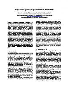
Glucose level too high
Fig. 4: General Scenario of the application A processing node, called the Room Manager, is responsible for collecting all the measures taken by different sensors and medical devices. Several rooms have associated the same Room Manager. Finally, there is a central processing node called the Central System to communicate with all the Room Managers of the residence, and to which only medical personnel has access. Fig. 5 shows the architecture of a plant of the residence, consisting of four rooms. To illustrate the modelling of reconfiguration, a simple use case of a biomedical measurement is represented in Fig. 5. The application is activated periodically in order to take a measurement of the glucose. The value is stored in the repository of the patient and, if it exceeds a certain threshold considered critical, an alarm is sent that triggers a new SOA. This latter executes a processing algorithm that may result in the activation of a set of SOAs in charge of sending messages to the medical staff and the patient and it also activates the measurement of the pulse of the patient. The Specification Model is performed through UML Component Diagrams. Note that the specification can be hierarchical, as an element of the specification graph can be a new SOA having its own activation properties and its own nonfunctional requirements.
+,-../,0!123*1*"'%'45" Fig. 2: Implementation of Wrappers in UML
Fig. 3: generic template of wrappers 4. CASE STUDY: Healthcare application The proposed case study includes an implementation of home care in a nursing home with mobility. The main objective of the application is the monitoring of biomedical variables for the elderly in response to alarm situations as quickly as possible, trying to avoid situations of service failure. An alarm can be triggered by different conditions, for instance the measurement of biomedical variables is outside the range considered acceptable. Each patient has associated a room equipped with both environmental sensors that collected information regarding the room itself (such as temperature, smoke detector or motion detector), and a set of medical devices (such as blood glucose meter, pulse oximeter or vascular). The rooms also feature a display by which you can display warning messages, and an IP camera is activated only in case of emergency. In addition, each patient shall incorporate biomedical sensors to determine body temperature and pulse, and a panic button to call for help. The staff is equipped with a PDA through which they receive messages of alarms and access patient records.
From the Specification Graph and the associated QoS requirements, as well as the descriptions of service implementations and hardware resources in the Infrastructure Model, the iLAND middleware can select the best execution graph to assure that all non-functional requirements are met. The Deployment Model is then generated using the available middleware services for creating and destroying SOAs and implementation of the logic corresponding to the specific wrappers (through pre-defined templates) as well as the service implementation selected by the iLAND middleware. 5. CONCLUSIONS This paper proposes a model-based approach for achieving run-time reconfiguration of distributed embedded applications having QoS requirements. The proposed approach supports the development of this type of applications based on the iLAND middleware. The model transformation is achieved by the middleware components during run-time triggered by the definition of a new application or by the reconfiguration of existing ones. Currently the modelling is being validated in the other two application fields of the iLAND project.
14950
Preprints of the 18th IFAC World Congress Milano (Italy) August 28 - September 2, 2011
Fig. 5: Specification of Glucose Monitoring SOA
ACKNOWLEDGEMENTS To each and every member of the iLAND consortium: Visual Tools S.A, Universidad Carlos III de Madrid, Trialog, University of Twente, Twente, Institute of Wireless and Mobile Communications, Universidad del País Vasco, University of Porto, Embedded Tecnologies Innovation Center, University of Pennsylvania. This project has been partially funded by the Spanish Ministry of Industry, Trade and Tourism and the ARTEMIS Joint Undertaking under Project contract 100026, and national EU member states part of the iLAND consortium. REFERENCES AADL, (2002). As-2 Embedded Computing Systems Committee SAE.” Architecture Analysis & Design Language (AADL)”. Nov 2004. SAE Standards AS5506 E. Bruneton, T. Coupaye, M. Leclercq, V. Qu´ ma, J.B. Stefani (2006). “The Fractal Component Model and its Support in Java”. Software Practice and Experience (SPE) 2006; 36(11-12):1257–1284. e3CM, (2003). Embedded Component Container Connector Model. Web site: http://www.ec3m.net/ García-Valls, M. and F. Gómez-Molinero (2010). iLAND: mIddLewAre for deterministic dynamically reconfigurable NetwokeD embedded systems. Embedded World Conference. Nuremberg, Germany. Grady Booch, James Rumbaugh, Ivar Jacobson (2005), “Unified Modeling Language User Guide”, 2nd Edition. Henzinger, T.A. (2008). Two challenges in embedded systems design: Predictability and robustness. Philosophical
Transactions of the Royal Society A, 366:3727–3736, 2008. Jan, M., C. Jouvray, F. Kordon, A. Kung, J. Lalande, F. Loiret, J. Navas, L. Pautet, J. Pulou, A. Radermacher, L. Seinturier (2010). Flex-eWare: a Flexible MDE-based Solution for Designing and Implementing Embedded Distributed Systems. Software – Practice and Experience, doi 10.1002/spe. Kopetz, H. (2008). The complexity challenge in embedded system design. In ISORC, pages 3–12. Krishnakumar Balasubramanian, Aniruddha Gokhale, Gabor Karsai, Senior, Janos Sztipanovits, and Sandeep Neema, (2006). “Developing Applications Using Model-driven Design Environments”. IEEE Computer Vol: 39 Issue: 2, pp:33-36. OMG (2003). MARTE, website: http://www.omgmarte.org/ OMG (2006a). “Deployment and Configuration of Component Based Distributed Applications”, v4.0 2006. OMG document formal/2006-04-02. OMG (2006b). “CORBA Component Model Specification”, Version 4.0 2006. OMG Document formal/2006-04-01. Russell Miles (2006) Learning UML 2.0, O'Relly ISBN: 0596009828. Schmidt, H., (2003). Trustworthy components: compositionality and prediction. Journal of Systems and Software 65 (3), 215–225. Sha, L., T, Abdelzaher, K.E. Årzén, A. Cervin, T. Baker, A. Burns, G. Butazzo, M. Caccamo, J. Lehoczky, A. Mok. (2004). “Real Time Scheduling Theory: A Historical Perspective.“ Real-Time Systems, 28, 101-155. Zurawski, R. (2005). Embedded systems. CRC Press Inc, 2005.
14951