Sensorless and Neural Network Control of an Induction Motor .... wwE w. Q. = = = = (10). Proceedings of the 6th WSEAS International Conference on Power ...
Proceedings of the 6th WSEAS International Conference on Power Systems, Lisbon, Portugal, September 22-24, 2006
279
Application of EKF to Parameters Estimation for Speed Sensorless and Neural Network Control of an Induction Motor KRIM YAZID1, RACHID IBTIOUEN2, OMAR TOUHAMI2 and MAURICE FADEL3 Laboratoire de Robotique Parallélisme et Electro-énergétique, Département d’Electrotechnique 1 Université des Sciences et de la Technologie Houari Boumediene BP.32 EL Allia, Alger, 16111 Algérie. 2 Département de Génie Electrique Ecole Nationale polytechnique 10 AV Pasteur, El-Harrach, Alger Algérie. 3 Laboratoire d’Electrotechnique et d’Electronique Industrielle ENSEEIHT Toulouse, 2 Rue Camichel BP 7122 - 31071 Cedex7, France. Abstract: - The rotor circuit time constant is an important parameter for indirect field oriented control. Incorrect estimation of the rotor time constant also leads to incorrect flux angle calculations and can cause significant performance deterioration if no means for compensation or identification is applied. The magnetic saturation, the operating temperature and difficulties in using sensors for speed measurement are one of the sources of parameters variations, caused by non-linear nature of the magnetizing curve and the variations of the rotor resistance. The classical indirect field-oriented control is highly sensitive to the inductance values decrease when increasing the saturation level. To solve this problem, the extended Kalman Filter associated to the neural network (EKF-ANNs) trained off line algorithm are used to estimate the rotor resistance, the main inductance and the rotor speed. The proposed EKF-ANNs compensation has shown a good performance in both the transient and steady state operations even in the presence of noise, and also at either variable speed operation in the field-weakening region or in the load variation. Key-Words: - Induction motor - Field oriented control – Neural Network – Extended Kalman Filter
1 Introduction The development of high-performance motor drives is very important in industrial applications. Nowadays, the field induction motor [1]-[15] can be applied for highperformance industrial applications where, traditionally, only the dc motors were used. In general, the requirements for high-performance motor drive system include the following effects: thermal, skin and saturation effects leading to local variations in the induction motor parameters. In particular, the slip frequency is highly affected by change of rotor time constant. Therefore, the variations of this parameter directly influence the performances in both transient and steady state operations. Thus, the compensation is necessary [2, 3] to include the inductances dependencies on saturation and the resistances at the present temperatures. In order to solve the previous problems, the conception of a compensation controller is of capital
importance to achieve the decoupling between the flux and the torque [4, 5]. Artificial neural networks (ANNs) are non-linear methods and adaptive in nature, giving robust performance with parameter variation problem [6, 7]. Recently, some approaches have been developed for control using ANN controller in vector control of induction motors operating in linear magnetizing curve [6, 7, 8]. For example, [6] proposes a novel speed estimation method of an induction motor using neural network trained on line. In [7], the authors present an off line application of ANNs in indirect field oriented control system. Reference [9] proposes a novel approach with the induction motors using direct and indirect application and [8] proposes an on line ANNs diagnosis of induction motor faults. Another approach using the fuzzy logic bloc is based on a sensitivity analysis to
Proceedings of the 6th WSEAS International Conference on Power Systems, Lisbon, Portugal, September 22-24, 2006
uncertainties in the rotor resistance and the mutual inductance of the induction motor [10]. In most speed and controlled drive systems, closed-loop control is based on the measurement of speed or position of the motor using a shaft encoder. However, it is difficult to use sensors for speed measurement. Recently some approaches have been developed to eliminate the speed sensor [11, 12]. In these strategies, the motor speed is estimated and used as feedback signal for closed-loop control. As one of the methods for estimating the induction motor parameters, the extended Kalman Filter (EKF) technique has been investigated by some authors [11, 13, 14, 15]. The extended Kalman filter estimators are designed using stochastic principles; they assume a noisy environment. Kalman filter theory is based on the assumption that all of the system noise disturbances are white and Gaussian probability distribution. For example, an extended Kalman filter approach for rotor time constant estimation is proposed in [13] and some parameter sensitivity diagrams are shown. In this paper, the authors present an improved conventional-based technique using artificial neural networks associated to the extended Kalman Filter (EKF-ANNs). The proposed algorithm is applied to compensate the saturation and the thermal effects by the estimation of the rotor resistance, the main inductance and the rotor speed in vector controlled induction motor. The induction motor behavior during changes in saturation level for various working points is discussed both in transient and steady state operations.
280
most appropriate. The discrete time varying model is deduced from continuous model by applying the Euler formula (first order).
3 Extended Kalman Filter The extended Kalman filter allows simultaneous estimation of states and parameters. These parameters are considered as extra states in an augmented state vector. This augmented model is non-linear because of multiplication of states. Thus, it must be linearized along the state trajectory to give a linear perturbation model. The state noise W and measurement noise V can be any combination of harmonics and Gaussian white noise with zero-mean and covariance σ2w and σ2v [11-15]. The discrete state induction motor model is considered in the synchronous rotating and rotor flux oriented d-q reference frame for implementing the extended Kalman Filter algorithm. ⎧ξ ( k + 1) = g (ξ ( k ), U ( k ), k ) + W ( k ) ⎨ ⎩η ( k ) = H ( k )ξ ( k ) + V ( k )
(2)
With: ⎡ f ( X , U , k )⎤ g (ξ (k ), U (k ), k ) = ⎢ ⎥ , Θ(k) = [Rr ⎣ Θ( k ) ⎦
Lm
Ω]
(3)
A nonlinear recursive filter based on the EKF is obtained by the linearization of the above system around the states and applying an EKF to state vector and parameters estimation of an induction motor as follows:
•
Prediction of state ξ (k + 1) = g [ξ (k ), U (k ), k ]
2 Modeling of the Induction Motor The induction motor is considered in the synchronous rotating and rotor flux oriented d-q reference frame [3, 6]. The model equations are: ⎡ ⎛ ⎤ L ⎞ L L ⎟ I ds + ω sσLs I qs + m Φ dr + m ω m Φ qr + Vds ⎥ ⎢ − ⎜⎜ Rs + Lr Tr ⎟⎠ L r Tr Lr ⎢⎣ ⎝ ⎥⎦ 2 ⎡ ⎤ dI qs ⎛ Lm ⎞ L L 1 ⎟ I qs − ω sσLs I ds + m Φ qr − m ω m Φ dr + V qs ⎥ = ⎢ − ⎜ Rs + dt Lr Tr ⎟⎠ σLs ⎢⎣ ⎜⎝ L r Tr Lr ⎥⎦ dΦ dr Lm 1 = I ds − Φ dr + (ω s − ω m )Φ qr dt Tr Tr dΦ qr Lm 1 = I qs + Φ qr − (ω s − ω m )Φ dr dt Tr Tr d Ω 1 ⎡ Lm (Φ dr I qs − Φ qr I ds ) − C r − fΩ ⎤⎥ = ⎢p dt J ⎣ Lr ⎦ 2 m
dI ds 1 = dt σLs
[X& ] = f ( X , U , t ) X = [I I Φ [U ] = [V V ] ds
ds
qs
dr
Φ qr
]
(1)
qs
The parameter estimation of an induction motor being implemented on a computer, a time-discrete model is the
•
(4)
Estimation of error covariance matrix
P(k + 1) = A(k ) P(k ) A t (k ) + Q
•
Kalman filter gain
[
K = P (k + 1) H t (k ) H (k ) P (k + 1)H t (k ) + R
(5)
]
−1
(6)
State estimation ξ(k + 1) = ξ(k + 1) + K[y(k ) − H(k )ξ(k )]
(7)
•
Update of the error covariance matrix P(k + 1) = P(k + 1) − KH (k ) P(k + 1)
(8)
Where y(k ) represents the measured current. A(k ) =
∂g ⎡1 0 0 0 0 0 0⎤ , ∂ξ H (k ) = ⎢⎣0 1 0 0 0 0 0⎥⎦
{ } R = cov(v ) = E{vv }
Q = cov(w) = E ww ' '
(9) (10)
Proceedings of the 6th WSEAS International Conference on Power Systems, Lisbon, Portugal, September 22-24, 2006
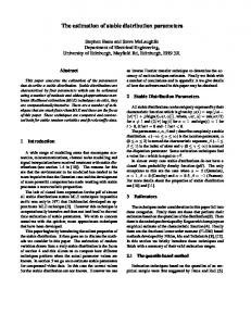
The estimation of the instantaneous angular position of the rotor flux space vector on indirect control by E.KF is shown in Fig.1. V ds
Φ dr E
V qs I ds
I qs
281
ev(k) ev(k-1) Cref(k-1)
Cref(k)
λi(k) λi(k-1) Visref(k-1)
Visref(k)
Φr
Φ qr
I qs
ω
L M I qs R r
(L M
K
Rr F
sl
+ L r 0 )Φ r
ωs
∫
θ
s
LM
ωm
Fig.1 Instantaneous angular position of the rotor flux space vector estimator based on the E.K.F
Input layer
Hidden layer
Output layer
Fig. 2 Neural network structure e v (k ) = Ω * (k ) − Ω(k ) * − I is λ (k ) = I isref
4 EKF-ANNs Bloc Firstly, the whole bloc has been considered and replaced by a neural network [15]. Then several tests affecting the architecture topology are examined: • • • • •
Number of neurons of the hidden layers Hidden layers number Inputs number Examples number Training algorithm
The network doesn't converge because of the particularly fact that a large number of parameters, is needed during the training process. Therefore, the F.O.C’s bloc is divided in to three sub-blocs neural. The structure of the proposed neural network is depicted in Fig.2. Each subbloc has three layers. The output layer has one neuron corresponding to the command values. The input layer has three neurons and the hidden layer has five neurons. The sigmoid functions are used at hidden layer and the linear function is used at the output layer. The algorithm used for training is Levenberg-Marquardt. For the first sub-bloc, in torque control, the neural network converges to a sum-squared error below 10-7 after only 1056 iterations. For the second sub-bloc, in voltage Vqsref control, the ANN converges to a sum-squared error below 10-5 after only 2150 iterations and the third sub-bloc in voltage Vdsref control as 10-7 error after only 950 iterations.
(11)
i = d, q
5 Simulation Results The fig.3 shows the proposed structure for parameters estimation by EKF associated to the FOC neural network. F.O.C NEURAL
Va Vb Vc
INVERTER
IM
θs ω sl
e jθs
V dq (k )
ξ (k ) E.K.F
I dq (k )
Fig.3 Block diagram of control system. The parameters of the induction motor used in computer simulation are listed in the appendix. The PWM inverter considered that stator voltage equations of the induction motor can be omitted from the model and it can be assumed that the actual stator voltages are equal to the controlled voltages [5]. In the simulated test, the variation of the rotor resistance increases to 50% and the magnetizing inductance decreases to 20%. Fig.4 shows the rotor speed and the estimated speed of the Kalman filter, the motor torque and the reference torque, the rotor flux and the estimated flux d-q components, the motor and the estimated magnetizing inductances, the motor and the estimated rotor resistances (Ω) and the errors between the rated speed and the estimated speed of the EKF also as between the
Proceedings of the 6th WSEAS International Conference on Power Systems, Lisbon, Portugal, September 22-24, 2006
282
rated speed and the motor speed. Furthermore, under load of rated torque, the reference speed is the rated speed. The current and voltage random noises are present in the current and voltage sensors. At 0.75s a torque of 10 Nm is applied to the shaft. The ANNs controller quickly Tracks the speed to the reference speed within 0.25 s with a maximum speed drop of 7 rad/s. The time response to the reference speed is 0.2 s. The simulation results are presented in Fig.5 for operation in the field-weakening region of the slope variation command speed at the rated speed to 210 rad/s. The simulation results are presented in the Fig.6 for operation in the low speed (10 rad/s). At 0.7s a torque of 10 Nm is applied to the shaft. These results show good assumption of the proposed approach. Fig. 6 Simulation results at low speed (rad/s) Motor variables Estimated EKF variables Rated variables
6 Conclusion This paper analyses the impact of the variation of the main inductance, caused by the non-linear nature of the magnetizing curve without the cross-saturation phenomenon, and the variations of the rotor resistance on indirect vector control for induction motor sensorless speed. The proposed algorithm is applied to solve the problem of performance degradation during transients even in the presence of noise. Fig. 4 Simulations results a constant flux
A method using the extended Kalman Filter associated to the neural network (EKF-ANNs) trained off line algorithm is used to estimate the rotor resistance, the main inductance and the rotor speed, has been presented. Using the software Matlab, the simulations have been performed with satisfactory results. Tests on a 1.5 kW induction motor has proven the feasibility of the proposed approach.
Acknowledgements: This paper enters in the setting of a cooperation agreement international CMEP-Tassili under the 05MDU662 code
Fig. 5 Simulation results-Operation in the field weakening region.
Proceedings of the 6th WSEAS International Conference on Power Systems, Lisbon, Portugal, September 22-24, 2006
Appendix: Induction motor parameters Rated voltage: 380/220V-50Hz Rated Power: 1.5kW Rated speed: 1420 tr/mn Rated current: 6.4/3.7 Number of pole pair p=2 Rs=4.85Ω; Rr=3.805Ω; Ls*=0.274H; Lr*=0.274H; Lm*=0.258H ; Ls0*=0.016H ; Lr0*=0.016H Total inertia J=0.031 kg-m2 Friction coefficient f=1.136 10-3 Nm/rad/s Notations: s: stator index; r: rotor index; m: mutual index ; *: rated index; d,q: d-axis and q-axis synchronous reference frame; V: voltage; I: current; Φ: flux; Rs, Rr : stator, rotor resistance; Ls* ,Lr*; Lm*: stator, rotor and main inductance rated; Tr=Lr / Rr: rotor time constant; Tr0=Lr / Rr:; leakage rotor time constant; Cem, Cr: electromagnetic torque and load torque; ωs , ωm: stator, rotor angular frequency; ωsl: slip frequency; 0: leakage coefficient; Ω: mechanical speed; Ωrref :reference mechanical speed f: viscous friction coefficient; J: equivalent inertia; p: number of pole pairs; S=d/dt: differential operator;
References: [1] F. Blascheke, « The principle of field orientation applied to the new transvector closed-loop control system for rotating field machines”, Siemens Rev., vol. 39, pp. 217-220, 1972. [2] Garces L.J., “Parameter adaptation for speedcontrolled static AC drive with a squirrel cage induction motor”, IEEE Transaction on Industry Application, vol.16, n°2, April 1980, pp.173-178. [3] Benhaddadi, M., K. Yazid and R. Khaldi, “An effective identification of rotor resistance for induction motor vector control”, Proceedings of IEEE’97, Instrumentation and Measurement Technology Conference, May 1997, pp. 339-342, Ottawa,CA. [4] Vas P., M.Alakula, “Field oriented control of
283
saturated induction machine”, IEEE Transactions on Energy Conversion, vol. 5, n°1, March 1990, pp. 280289. [5] Levi, E., “Magnetic saturation in rotor flux oriented induction motor driver operating regimes consequences and open loop compensation”, ETEP, Vol.4, n°4, August 1994, pp. 277-286. [6] Kim, S-H., T. S. Park and G. Park, “Speed-Sensor less Vector Control of an induction motor using neural network speed estimation”, IEEE Transactions on Industry Electronics. vol. 48, n°3, June 2001, pp. 609614. [7] Mohamadian, M., E.P. Nowickit and F. Asharafzadeh, “Training of network controller Indirect Orientation Control”, IEEE CCEC'96, 0-7803-3143-5, 1996, pp. 615-618. [8] Filippetti, F., G. Franceschini, and C. Tassoti, “Neural network aided on-line diagnostics of induction rotor faults”, IEEE Transactions Industry Application. vol. 31, n°4, 1995, pp. 892-899 [9] Ba-Razzouk, A., A. Cheriti, “Field-control of induction motors Neural-Network Decouplers”, IEEE Transactions on Power Electronics. vol. 12, n°4, July 1997, pp. 752-763. [10] Robyns, B., F. Berthereau and J. Hautier, “A fuzzylogic-based Multimodel Field Orientation in an Indirect FOC of an Induction Motor”, IEEE Transactions on Industry Application. vol. 47, n°2, April 2000, pp. 380-388. [11] El. Moucary, G. Garcia Sato, E. Mendes, “Robust Rotor Flux Resistance and Speed Estimation of an induction Machine Using the Extended Kalman Filter” Proceedings of the IEEE, ISIE, Bled, Slovenia, 1999. [12] K. L. Shi, T. F. Chan, Y. K. Wong and S. L. Ho “ Speed Estimation Of An Induction Motor Drive Using Extended Kalman Filter”, IEEE’2000, 0-78035935-6/00/$10.00(c), pp. 243-248. [13] L. C. Zai and T. A. Lipo “An Extended Kalman Filter Approach to rotor time constant Mesurement in PWM induction Motor Drives” IEEE-IAS Annual Meeting Conference Rec., 1997, 177-183. [14] Iwasaki and Kataoka, “Application a of an Extended Kalman Filter to parameter Identification of an induction motor” IEEE Transactions on Industry Electronics, vol. 48, n°6, 1989, pp. 248253. [15] K. Yazid, M. Menaa, O. Touhami and R. Ibtiouen, “Application Of EKF To Parameters Estimation And Neural Network Control of an Induction motor”, Proceedings of ELECTROMOTION’05, 6th International Symposium on Advanced Electromechanical motion systems, 27-29 September 2005, Lausanne, Switzerland.