Nov 10, 2004 - blowing (RASB), to achieve wing rock suppression over a range of operating conditions. ... motion characterized by self-induced limit cycle roll.
494
International Journal of Control, Automation, andChoi, Systems, vol. 2,P.no. 4, pp. 494-500, December 2004 Sreenatha G. Anavatti, Jin Young and Pupin Wong
Design and Implementation of Fuzzy Logic Controller for Wing Rock Sreenatha G. Anavatti, Jin Young Choi, and Pupin P. Wong Abstract: The wing rock phenomenon is a high angle of attack aerodynamic motion manifested by limit cycle roll oscillations. Experimental studies reveal that direct control and manipulation of leading edge vortices, through the use of ‘blowing’ techniques is effective in the suppression of wing rock. This paper presents the design of a robust controller for the experimental implementation of one such ‘blowing’ technique – recessed angle spanwise blowing (RASB), to achieve wing rock suppression over a range of operating conditions. The robust controller employs Takagi – Sugeno fuzzy system, which is fine-tuned by experimental simulations. Performance of the controller is assessed by real-time wind tunnel experiments with an 80 degree swept back delta wing. Robustness is demonstrated by the suppression of wing rock at a range of angles of attack and free stream velocities. Numerical simulation results are used to further substantiate the experimental findings. Keywords: Fuzzy Logic Controller (FLC), robust, spanwise blowing, wing rock.
1. INTRODUCTION Wing rock – a high angle of attack aerodynamic motion characterized by self-induced limit cycle roll oscillations is one of the significant limitations to combat effectiveness of modern fighter aircrafts. This aerodynamic phenomenon causes loss of control in the lateral/directional mode, which severely limits the maneuvering envelope of high performance fighter aircrafts. An approximate nonlinear mathematical model has been proposed by Nayfeh et al [1,2] to predict the wing rock motion experience by a slender delta wing model. The underlying mechanism for wing rock motion is not clearly understood [3]. However, in recent years, several theories have been put forward to explain the wing rock phenomenon.[3-6]. These studies suggest that vortex formation plays an important role during wing rock. As such, several studies have been extended towards investigating different techniques to manipulate and control these vortices. The aerodynamic suppression of ‘blowing’[7-9] has been of great interest, as it is found to be highly effective in __________ Manuscript received December 31, 2003; accepted November 10, 2004. Recommended by Editorial Board member Eun Tai Kim under the direction of Editor Jin Bae Park. Sreenatha G. Anavatti and Pupin P. Wong are with the School of Aerospace, Civil and Mechanical Engineering, University of New South Wales, Australian Defence Force Academy, Canberra, Australia 2600 (e-mail: agsrenat@adfa. edu.au). Jin Young Choi is with the School of Electrical and Computer Engineering, Seoul National University, Kwanak, P.O.Box 34 (#048), Seoul 151-600, Korea (e-mail: jychoi@ neuro.snu.ac.kr).
controlling vortex orientation. Sreenatha and Ong[10] have employed the technique of RASB implemented by a simple rule-based controller. Flow visualisation results presented by them demonstrated the potential robustness of RASB in wing rock control. In recent years, the fuzzy logic has become a popular design paradigm in robust control in systems that lack an accurate mathematical model [11]. The approximate and inexact nature of wing rock can be effectively captured using fuzzy logic, which is a logical system closer in spirit to human thinking and natural language. Various researches have employed fuzzy logic in investigating control for wing rock. Tarn and Hsu[12] presented a rule-based fuzzy controller for wing rock. Sreenatha and Lim[13] have presented a controller based on the Mamdani fuzzy system. However, only numerical results have been presented to demonstrate the robustness of the fuzzy controllers. The implementation of a fuzzy logic controller (FLC) to employ RASB, promises robust control of wing rock experienced by the experimental model over a wide range of flight conditions. Results of this implementation will also further substantiate the suitability of FLC as robust controller for plants with non-linear dynamics both in software simulation and actual model experiments. Section 2 presents the numerical model currently available to represent wing rock. The experimental set up is described in Section 3. The design of FLC is presented in Section 4. Section 5 discusses the modifications carried out on the basic FLC design to improve the performance and robustness. The automation of the FLC with the delay time is presented in Section 6. The numerical results to
Design and Implementation of Fuzzy Logic Controller for Wing Rock
validate the controller design are presented in Section 7. Section 8 concludes the paper.
2. NUMERICAL MODEL The dynamic equation governing wing rock is given by [1,2];
φ�� + ω 2φ = µ1φ� + b1φ�3 + µ 2φ 2φ� + b2φφ�2 ,
(1)
where ω 2 = - c1 a1, µ1 = c1 a2 – c2 , b1 = c1 a3, µ 2= c1 a4 and b 2 = c1 a5. Also, φ stands for the roll angle and dot (.) indicate differentiation with respect to time. The coefficients of the wing rock model vary with angle of attack and are shown in Table 1. Table 1. Coefficients of wing rock model. α
a1
a2
a3
a4
15°
-0.01026
-0.02117
-0.14181
0.99735
21.5°
-0.04207
0.01456
0.04714
-0.18583
22.5°
-0.04681
0.01966
0.05671
-0.22691
25°
-0.05686
0.03254
0.07334
-0.3597
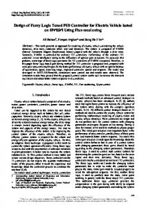
(a) Phase plot of wing rock.
(b) Typical time history. Fig. 1. Phase plot of Wing Rock and Typical Time history.
495
Fig. 1 shows the phase plot for (1). Limit cycle oscillations are reflected in the phase plot. A typical time history is also depicted in Fig. 1. The amplitude of the stable limit cycle depicted is roughly 37o and the frequency is about 3 Hz for 25o angle of attack. The model is an approximate one obtained by curve fitting employing the experimental data for a particular wing rock model in the wind tunnel.
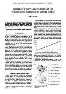
3. EXPERIMENTAL SETUP The 80-deg swept angle delta wing employed in the present work has a sharp leading edge and an aspect ratio of 0.705. The wing is of aluminium construction and weighs 113g. The wing’s internal structure includes two symmetrical longitudinally separated chambers of 1.5mm thickness. This provides two cavities for air passage through the left and right portion of the wing. Twelve blowing ports of 1.0mm in diameter are drilled in each side of the wing at the same beveled angle of 45 deg to the wing surface, shown in Fig 2. This slender delta wing is mounted on low friction bearings to allow it to rotate freely about its longitudinal axis. A dSpace MiniboxTM provides the I/O interface, which is used for data acquisition and processing. This dSpace equipment and corresponding development tools allow hardware-in-the-loop testing of program codes by providing seamless interaction between the production codes of controllers and the hardware. Online-tuning and manipulation of design parameters is carried out on the personal computer linked to the dSpace Minibox, which also stores and display the data. The block diagram of the experimental setup is shown in Fig 3. The critical angle where wing rock is experienced by the wing model is at 19 deg and 18m/s.10 The electronic proportional directional control valve has two output channels that are connected to each side of the wing via rubber tubes. The valve-slide
Fig. 2. Schematic plan and back view of the slender delta wing model. (All dimensions are in millimetres. Not drawn to scale.)
496
Sreenatha G. Anavatti, Jin Young Choi, and Pupin P. Wong
(a) Roll angle. Fig. 3. Block diagram of the experimental set-up. stroke of this control valve can be controlled to a specified set point by an analog electrical input signal. Therefore, the control valve can control the flow rate of the pressurized air supply by way of magnitude and direction. An electrical input signal generated from the FLC controller in the PC via dSpace, commands the switching of the valve-slide stroke between its two output channels to supply the air into either side of the wing at the required pressure.
4. DESIGN OF FLC Mamdani implication expects the output membership functions to be fuzzy sets. After the aggregation process, there is a fuzzy set for each output variable that needs defuzzification. It's possible, and in many cases much more efficient, to use a single spike as the output membership function rather than a distributed fuzzy set. This is sometimes known as a singleton output membership function, and it can be thought of as a pre-defuzzified fuzzy set. It enhances the efficiency of the defuzzification process because it greatly simplifies the computation required by the more general Mamdani method, which finds the centroid of a two-dimensional function. Rather than integrating across the two-dimensional function to find the centroid, the weighted average of a few data points is used. The Takagi-Sugeno implication systems support this type of model. In general, Takagi-Sugeno implication systems can be used to model any inference system in which the output membership functions are either linear or constant [14]. Due to the linear dependence of each rule on the system's input variables, the Sugeno method is ideal for acting as an interpolating supervisor of multiple linear controllers that are to be applied, respectively, to different operating conditions of a dynamic nonlinear system. The FLC developed in Ref 13 is effective in suppressing wing rock over a range of flight conditions using numerical simulations. This numerically designed FLC is converted to Sugeno fuzzy system and adapted to employ RASB in the wind tunnel experimentations. The membership functions are shown in Fig. 4. The domains used in the membership function for φ
(b) Roll rate. Fig. 4. Membership function of (a) roll angle and (b) roll rate.
Table 2. Fuzzy control table.
φ�
PB
ZO
BL
BR
BR
PS
BL
ZO
BR
BR
NS
BL
BL
ZO
BR
NB
BL
BL
BR
ZO
NB
NS
PS
PB
φ and φ� are representative of the maximum values of roll and roll rate characteristics of wing rock experienced on the experimental model within the operating envelop. The convention is such that roll angle is positive when the wing is rolling to the right and vice versa. The domain of the control input relates to the proportional and directional properties of the control valve. The magnitude of u determines the amount of valve opening, where value of 5 depicts the valve fully opened. The sign of u determines the direction, where negative depicts the valve is opened on the left, effecting blowing on the left portion of the wing. The output membership function consists of three constants: BL (Blow Left), BR (Blow Right) and ZERO (No blowing), with corresponding values of –5, 5 and 0. This is reflective of the proportional and directional characteristics of the control valve described. The “weighted sum” defuzzification strategy is employed here. This ensures the output BL or BR is always –5 or 5 respectively, to generate a pulsed control input, thereby effecting full blowing on either side of the wing. The output is determined from the set of fuzzy rules summarized in tabular form in
497
Roll Angle, Roll Rate, Control Input(Scaled, Non-dimensionless)
Design and Implementation of Fuzzy Logic Controller for Wing Rock
(a) With no time delay. Fig. 5. Control logic of FLC. Table 2. For example, if φ is NB and φ� is NB then u is BL. Previous pressure transducer studies involving the control system highlighted the significance of Electromechanical lag present in the servo control valve.10 These rules are modified from the simple rule base used in Ref 10 to incorporate “advance blowing” to account for the Electro-mechanical lag present in the system. The control logic is shown in Fig. 5. The designed FLC is implemented onto the dSpace environment and real-time experimental simulation was conducted to investigate its effectiveness. However, the FLC was unable to achieve suppression of the wing rock motion experienced by the experimental model. There was no significant reduction of wing rock amplitude with the application of the redesigned FLC under all conditions within the operating envelope. Therefore, it can be concluded that the advance blowing employed in the formulation of the fuzzy rule-base is ineffective in overcoming the electro-mechanical lag.
5. MODIFICATIONS TO FLC The problem posed by the electro-mechanical lag is that the physical “blowing” is not occurring at the specific points of each cycle of wing rock. Therefore, it is necessary to incorporate additional phase shift, to ensure that the physical “blowing” of air out of the blow ports of the wing occurs at the specific points within the wing rock cycle. Addition of a delay function in the control system, allows real-time alteration of the delay time imposed on the control input. This delay function allows the control action formulated in the FLC to be stored for a specified time (corresponding to the delay time) before passing into the control system. By choosing the correct delay time, the onset of physical “blowing” at the wing can be
(b) With a time delay of 15 ms. Fig. 6. Wing rock motion at 22o AOA, 28 m/s with (a) FLC applied with no delay time and (b) FLC applied with delay time of 15ms.
altered accordingly, to ensure that “blowing” occurs at the specific points within the wing rock cycle. Subsequent wind tunnel experiments with varying values of delay time, revealed significant improvement in controller performance. By incorporating a delay time of 15ms on the control input, wing rock suppression was achieved at freestream velocities below 24 m/s. At higher free-stream velocities, smaller delay times are required. The effect of delay times on wing rock suppression is clearly shown in Fig. 6. This FLC is not ideal as it lacks automation. The above successful suppression is achievable only with the manual incorporation of delay to the control input, which is required at all flight conditions. Another means to overcome the electro-mechanical lag other than delaying the control input is by fine-tuning the input membership functions.
498
Sreenatha G. Anavatti, Jin Young Choi, and Pupin P. Wong
Experimental trials were conducted with different input membership functions whilst the fuzzy rules and output membership functions remain unchanged. The trial-and-error experiments attempt to achieve successful suppression of wing rock, without the need to incorporate delay to the control input. The conclusion that results from the numerous trials is as follows: 1) Fine-tuned input membership functions will achiev e suppression of wing rock without the need to imp lement delay to control input; however, 2) Successful suppression is only achievable within a very narrow operating envelope, which does notme et the design criteria.
database will output a delay time based on the input, which in this case is the free-stream velocity. This database is incorporated in the control system block diagram as shown in Fig. 8. The addition of this time-lag database imparts auto mation to the FLC, whereby experiments are carried o
6. AUTOMATION OF FLC The delay time implemented in the FLC is via manual user input, when flight conditions changes. Since the incorporation of delay to the control input is inevitable, further research was carried out to investigate the possibility of incorporating some form of database, which will implement the delay time automatically. Extensive experimentations with the FLC design revealed that the required delay time is a function of free-stream velocity. Furthermore, the delay time required remains unchanged at different AOA. This is expected, as the change in wing rock frequency with AOA is small. In contrast, frequency increases significantly with free-stream velocity. This reduction of wing rock period at high free-stream velocities renders the electro-mechanical lag increasingly significant, such that required delay time changes. Fig. 7 shows the variation of delay times with free-stream velocity. The data from Fig. 7 is entered into a time lag database in the form of a look-up table. The
Fig. 8. Time-lag database incorporated into the control system block diagram.
(a)
(b) Fig. 7. Required delay time.
Fig. 9. Wing rock suppressed at (a) 21o AOA, 18m/s and (b) 23o AOA, 33m/s.
Design and Implementation of Fuzzy Logic Controller for Wing Rock
499
wing when the left wing is deflected down, reaction force will act to increase the wing rock amplitude rather than suppressing it. Therefore, the control logic gives sufficient confidence that the designed FLC employs suppression by aerodynamic means only. 7. NUMERICAL SIMULATION
(a)
(b) Fig. 10. Simulation at (a) 21.5o AOA, initial roll = 40o, initial roll rate = 700o/s and (b) at 22.5o AOA, initial roll = -60o, initial roll rate = 1000o/s. ut at different flight conditions and the only user input required is to toggle the gain switch for the FLC, whi ch functions as an on/off switch. This automated FLC is subjected to real-time experimental simulations at all flight conditions of the operating envelop specified in the design criteria. The experimental results revealed suppression of wing rock in accordance with the performance specifications. Examples of successful suppression are included in Fig. 9. Since the requirement of the FLC is to achieve aerodynamic suppression, investigation has to be carried out to ensure the reaction force is not driving the control effort. The FLC control logic shown in Fig. 5 provides evidence that reaction force is not involved in the suppression of wing rock. By convention, the roll angle is negative when the left wing deflects down from the horizontal plane, and a negative control signal will open the valve to the left to “blow” on the left portion of the wing. Since the control logic reveals that the “blowing” is occurring on the left
To reinforce and verify the experimental findings, numerical simulations were conducted with the final design of the FLC. Numerical simulations are based on the analytical model of wing rock presented in Section 2. MATLAB/SIMULINK is used to run the numerical simulation. As the analytical model is a function of AOA and initial condition only, simulations were carried out at a range of AOA available to the model, with different initial conditions. A typical set of results are shown in Fig. 10. The amplitude of oscillation is reduced to negligibly low levels after about six oscillations in less than three seconds. Furthermore, the limit cycle oscillations associated with wing rock is destroyed and replaced with a new equilibrium at the origin. Therefore, these results demonstrate the ability of the final design of FLC to suppress wing rock predicted by the analytical model. This further substantiates the experimental results and thereby confirms the suitability of fuzzy controller for control of wing rock in aircrafts via RASB.
8. CONCLUSION In this paper, we have developed a robust fuzzy logic controller to implement the RASB technique of aerodynamic suppression to control wing rock on single delta wing model. The effectiveness and robustness of the controller is demonstrated by wind tunnel experiments, which reveal successful suppression of wing rock within the tested operating envelop. In addition, numerical simulations based on the analytical model reinforce the experimental findings, as the controller is able to suppress the wing rock predicted by the mathematical model also. Both experimental and numerical simulation results give sufficient confidence that fuzzy logic control system is suitable for implementing the RASB aerodynamic suppression in flight control systems in aircrafts.
[1]
[2]
REFERENCES A. H. Nayfeh, J. M. Elzebda, and D. T. Mook, “Development of an analytical model of wing rock for slender delta wings,” Journal of Aircraft, vol. 26, no. 8, pp. 737-743, August 1989. A. H. Nayfeh, J. M. Elzebda, and D. T. Mook, “Analytical study of subsonic wing rock phenomenon for slender delta wings,” Journal of Aircraft, vol. 26, no. 9, pp. 805-809, September
500
Sreenatha G. Anavatti, Jin Young Choi, and Pupin P. Wong
1989. A. S. Arena and R. C. Nelson, “Experimental investigation on limit cycle wing rock of slender wings,” Journal of Aircraft, vol. 31, no. 5, pp. 1148-1155, September-October 1994. [4] C. Hsu and C. E. Lan, “Theory of wing rock,” Journal of Aircraft, vol. 22, pp. 920-924, October 1985. [5] L. E. Ericsson, “Wing rock analysis of slender delta wings, review and extension,” Journal of Aircraft, vol. 32, no. 6, pp. 1221-1226, November-December, 1995. [6] L. Nguyen, L. Yip, and J. R. Chambers, “Selfinduced wing rock of slender delta wings,” AIAA Paper 81-1883, August 1981. [7] T. T. Ng, C. J. Suarez, and G. N. Malcom, “Forebody vortex control for wing rock suppression,” Journal of Aircraft, vol. 31, no. 2, pp. 298-305, March-April, 1994. [8] H. Johari, D. J. Olinger, and K. C. Fitzpatrick, “Delta wing vortex control via recessed angled spanwise blowing,” Journal of Aircraft, vol. 32, no. 4, pp. 804-810, July-August, 1995. [9] H. Johari and J. Moreira, “Delta wing vortex manipulation using pulsed and steady blowing during ramp-pitching,” Journal of Aircraft, vol. 33, no. 2, pp. 304-310, March-April, 1994. [10] A. G. Sreenatha and T. K. Ong, “Wing rock suppression using recessed angle spanwise blowing”, Journal of Aircraft, vol. 39, no. 4, pp. 50-54, July-August 2002. [11] D. Driankov, H. Hellendoorn, and M. Reinfrank, An Introduction to Fuzzy Control, Springer International Student Edition, Narosa Publishing House, New Delhi, 1996. [12] J. H. Tan and F. Y. Hsu, “Fuzzy control of wing rock for slender delta wings,” IEEE Region 10 Conference, Tencon 92, 11-13th, Melbourne, Australia, November 1992. [3]
[13] A. G. Sreenatha and Y. Lim, “Stability and robustness analysis of fuzzy logic controller for wing rock suppression,” AIAA Atmospheric Flight Mechanics Conference Denver, AIAA2000-4314, pp. 701-706, August 2000. [14] W. Chang, Y. H. Joo, J. B. Park, and G. Chen, “Robust fuzzy-model-based controller for uncertain systems,” Proc. of IEEE International Fuzzy Systems Conference, August 22-25, Seoul, Korea, pp. 486-491, 1999. Sreenatha G. Anavatti received the Ph.D. degree in Aerospace Engineering from Indian Institute of Science, Bangalore, India, in 1989. His research interests include application of fuzzy and neural networks for aerospace applications and UAV.
Jin Young Choi received the B.S., M.S. and Ph.D. degrees in Control and Instrumentation Engineering from Seoul National University, Seoul, Korea, in 1982, 1984, 1993, respectively. From 1984 to 1989, he joined the project of TDX switching system at the Electronics and Telecommunication Research Institute (ETRI). From 1992 to 1994, he was with the Basic Research Department of ETRI, where he was a senior member of technical staff working on the neural information processing system. Since 1994, he has been with Seoul National University, where he is currently Assistant Professor in the School of Electrical Engineering. He is also affiliated with Automation and Systems Research Institute (ASRI), Engineering Research Center for Advanced Control and Instrumentation (ERCACI), and Automatic Control Research Center (ACRC) at Seoul National University. From 1998. 8 to 1999. 8, he was Visiting Professor at niversity of California, Riverside.